2007 TOYOTA SIENNA sensor
[x] Cancel search: sensorPage 166 of 3000
AXLE – FRONT AXLE HUBAH–9
AH
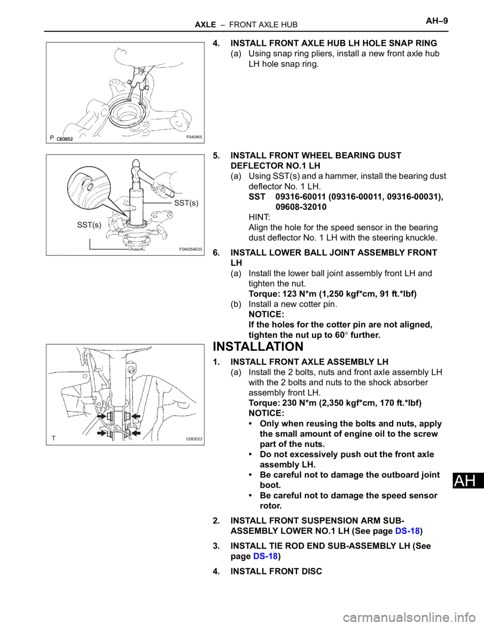
4. INSTALL FRONT AXLE HUB LH HOLE SNAP RING
(a) Using snap ring pliers, install a new front axle hub
LH hole snap ring.
5. INSTALL FRONT WHEEL BEARING DUST
DEFLECTOR NO.1 LH
(a) Using SST(s) and a hammer, install the bearing dust
deflector No. 1 LH.
SST 09316-60011 (09316-00011, 09316-00031),
09608-32010
HINT:
Align the hole for the speed sensor in the bearing
dust deflector No. 1 LH with the steering knuckle.
6. INSTALL LOWER BALL JOINT ASSEMBLY FRONT
LH
(a) Install the lower ball joint assembly front LH and
tighten the nut.
Torque: 123 N*m (1,250 kgf*cm, 91 ft.*lbf)
(b) Install a new cotter pin.
NOTICE:
If the holes for the cotter pin are not aligned,
tighten the nut up to 60
further.
INSTALLATION
1. INSTALL FRONT AXLE ASSEMBLY LH
(a) Install the 2 bolts, nuts and front axle assembly LH
with the 2 bolts and nuts to the shock absorber
assembly front LH.
Torque: 230 N*m (2,350 kgf*cm, 170 ft.*lbf)
NOTICE:
• Only when reusing the bolts and nuts, apply
the small amount of engine oil to the screw
part of the nuts.
• Do not excessively push out the front axle
assembly LH.
• Be careful not to damage the outboard joint
boot.
• Be careful not to damage the speed sensor
rotor.
2. INSTALL FRONT SUSPENSION ARM SUB-
ASSEMBLY LOWER NO.1 LH (See page DS-18)
3. INSTALL TIE ROD END SUB-ASSEMBLY LH (See
page DS-18)
4. INSTALL FRONT DISC
F045465
F045054E03
C083023
Page 167 of 3000
AH–10AXLE – FRONT AXLE HUB
AH
5. INSTALL FRONT DISC BRAKE CALIPER ASSEMBLY
LH
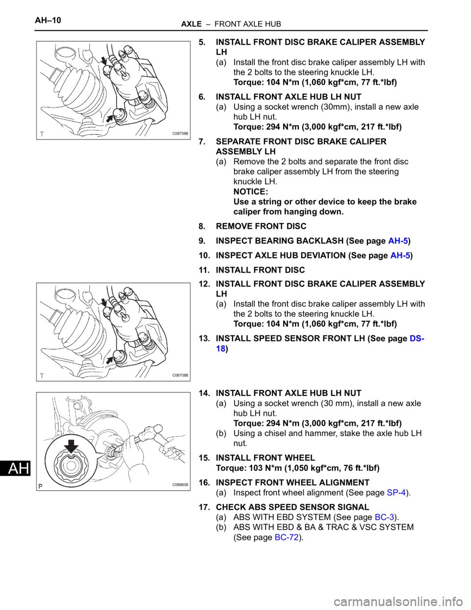
(a) Install the front disc brake caliper assembly LH with
the 2 bolts to the steering knuckle LH.
Torque: 104 N*m (1,060 kgf*cm, 77 ft.*lbf)
6. INSTALL FRONT AXLE HUB LH NUT
(a) Using a socket wrench (30mm), install a new axle
hub LH nut.
Torque: 294 N*m (3,000 kgf*cm, 217 ft.*lbf)
7. SEPARATE FRONT DISC BRAKE CALIPER
ASSEMBLY LH
(a) Remove the 2 bolts and separate the front disc
brake caliper assembly LH from the steering
knuckle LH.
NOTICE:
Use a string or other device to keep the brake
caliper from hanging down.
8. REMOVE FRONT DISC
9. INSPECT BEARING BACKLASH (See page AH-5)
10. INSPECT AXLE HUB DEVIATION (See page AH-5)
11. INSTALL FRONT DISC
12. INSTALL FRONT DISC BRAKE CALIPER ASSEMBLY
LH
(a) Install the front disc brake caliper assembly LH with
the 2 bolts to the steering knuckle LH.
Torque: 104 N*m (1,060 kgf*cm, 77 ft.*lbf)
13. INSTALL SPEED SENSOR FRONT LH (See page DS-
18)
14. INSTALL FRONT AXLE HUB LH NUT
(a) Using a socket wrench (30 mm), install a new axle
hub LH nut.
Torque: 294 N*m (3,000 kgf*cm, 217 ft.*lbf)
(b) Using a chisel and hammer, stake the axle hub LH
nut.
15. INSTALL FRONT WHEEL
Torque: 103 N*m (1,050 kgf*cm, 76 ft.*lbf)
16. INSPECT FRONT WHEEL ALIGNMENT
(a) Inspect front wheel alignment (See page SP-4).
17. CHECK ABS SPEED SENSOR SIGNAL
(a) ABS WITH EBD SYSTEM (See page BC-3).
(b) ABS WITH EBD & BA & TRAC & VSC SYSTEM
(See page BC-72).
C067088
C067088
C068609
Page 180 of 3000
BC–4BRAKE CONTROL – ANTI-LOCK BRAKE SYSTEM
BC
TEST MODE PROCEDURE
1. SPEED SENSOR SIGNAL CHECK (WHEN USING SST
CHECK WIRE):
HINT:
• If the ignition switch is turned from the ON to the ACC
or LOCK position during Test Mode, the DTCs of the
signal check function will be erased.
(a) Turn the ignition switch off.
(b) Check that the steering wheel is in the straight-
ahead position and move the shift lever to the P
position (Automatic Transmission) or apply the
parking brake (Manual Transmission).
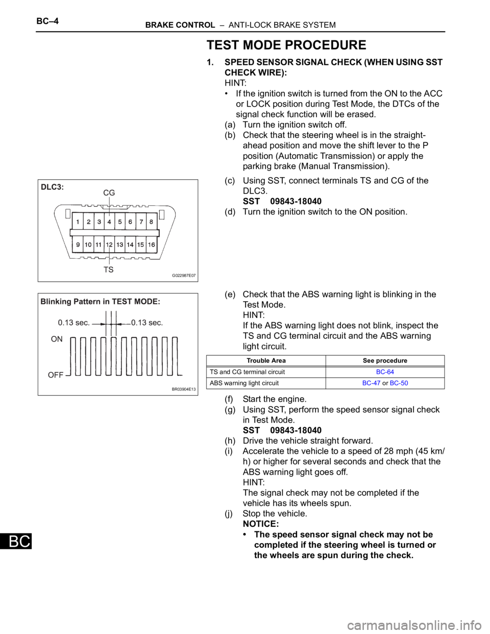
(c) Using SST, connect terminals TS and CG of the
DLC3.
SST 09843-18040
(d) Turn the ignition switch to the ON position.
(e) Check that the ABS warning light is blinking in the
Test Mode.
HINT:
If the ABS warning light does not blink, inspect the
TS and CG terminal circuit and the ABS warning
light circuit.
(f) Start the engine.
(g) Using SST, perform the speed sensor signal check
in Test Mode.
SST 09843-18040
(h) Drive the vehicle straight forward.
(i) Accelerate the vehicle to a speed of 28 mph (45 km/
h) or higher for several seconds and check that the
ABS warning light goes off.
HINT:
The signal check may not be completed if the
vehicle has its wheels spun.
(j) Stop the vehicle.
NOTICE:
• The speed sensor signal check may not be
completed if the steering wheel is turned or
the wheels are spun during the check.
G022987E07
BR03904E13
Trouble Area See procedure
TS and CG terminal circuitBC-64
ABS warning light circuitBC-47 or BC-50
Page 181 of 3000
BRAKE CONTROL – ANTI-LOCK BRAKE SYSTEMBC–5
BC
• After the ABS warning light goes off and if
vehicle speed exceeds 50 mph (80 km/h), the
signal check code will be stored again.
Decelerate or stop the vehicle before the
speed reaches 50 mph (80 km/h).
• If the signal check has not been completed,
the ABS warning light blinks while driving
and the ABS system does not operate.
HINT:
When the signal check has been completed, the
ABS warning light goes off while driving and blinks
in the Test Mode pattern while stationary.
2. READ DTC
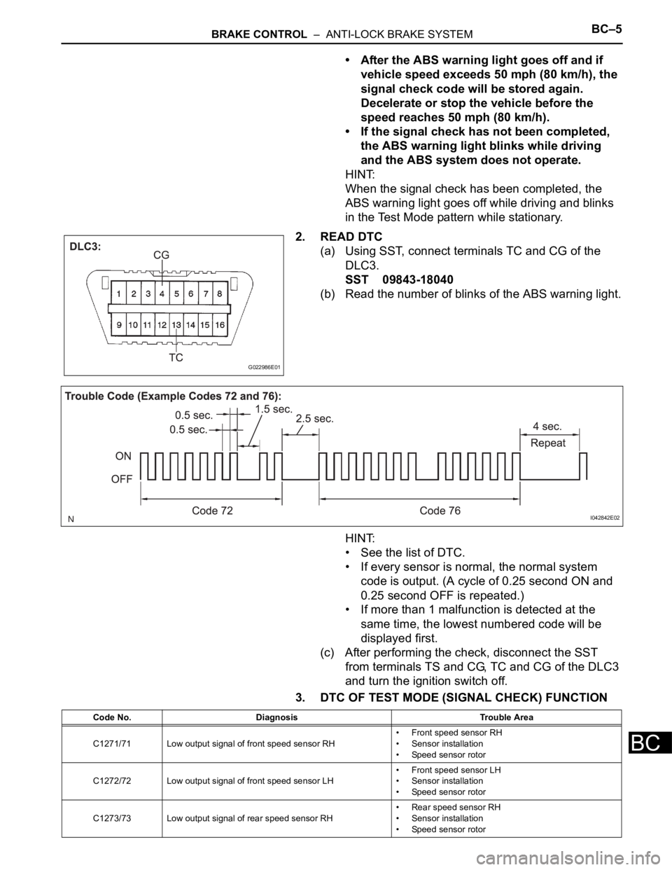
(a) Using SST, connect terminals TC and CG of the
DLC3.
SST 09843-18040
(b) Read the number of blinks of the ABS warning light.
HINT:
• See the list of DTC.
• If every sensor is normal, the normal system
code is output. (A cycle of 0.25 second ON and
0.25 second OFF is repeated.)
• If more than 1 malfunction is detected at the
same time, the lowest numbered code will be
displayed first.
(c) After performing the check, disconnect the SST
from terminals TS and CG, TC and CG of the DLC3
and turn the ignition switch off.
3. DTC OF TEST MODE (SIGNAL CHECK) FUNCTION
G022986E01
I042842E02
Code No. Diagnosis Trouble Area
C1271/71 Low output signal of front speed sensor RH• Front speed sensor RH
• Sensor installation
• Speed sensor rotor
C1272/72 Low output signal of front speed sensor LH• Front speed sensor LH
• Sensor installation
• Speed sensor rotor
C1273/73 Low output signal of rear speed sensor RH• Rear speed sensor RH
• Sensor installation
• Speed sensor rotor
Page 182 of 3000
BC–6BRAKE CONTROL – ANTI-LOCK BRAKE SYSTEM
BC
HINT:
The codes in this table are output only in Test Mode
(signal check).
4. SPEED SENSOR SIGNAL CHECK (WHEN USING
INTELLIGENT TESTER):
HINT:
• If the ignition switch is turned from the ON to the ACC
or LOCK position during Test Mode, DTCs of the
signal check function will be erased.
• During Test Mode, the ECU records all DTCs of the
signal check function. By performing the signal check,
the codes are erased if normality is confirmed. The
remaining codes are the codes where an abnormality
was found.
(a) Turn the ignition switch off.
(b) Check that the steering wheel is in the straight-
ahead position.
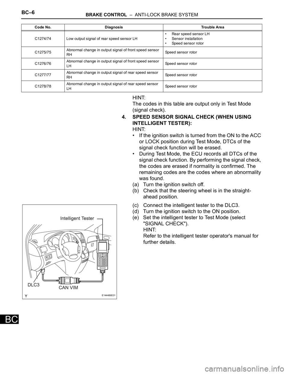
(c) Connect the intelligent tester to the DLC3.
(d) Turn the ignition switch to the ON position.
(e) Set the intelligent tester to Test Mode (select
"SIGNAL CHECK").
HINT:
Refer to the intelligent tester operator's manual for
further details.
C1274/74 Low output signal of rear speed sensor LH• Rear speed sensor LH
• Sensor installation
• Speed sensor rotor
C1275/75Abnormal change in output signal of front speed sensor
RHSpeed sensor rotor
C1276/76Abnormal change in output signal of front speed sensor
LHSpeed sensor rotor
C1277/77Abnormal change in output signal of rear speed sensor
RHSpeed sensor rotor
C1278/78Abnormal change in output signal of rear speed sensor
LHSpeed sensor rotor Code No. Diagnosis Trouble Area
E144486E01
Page 183 of 3000
BRAKE CONTROL – ANTI-LOCK BRAKE SYSTEMBC–7
BC
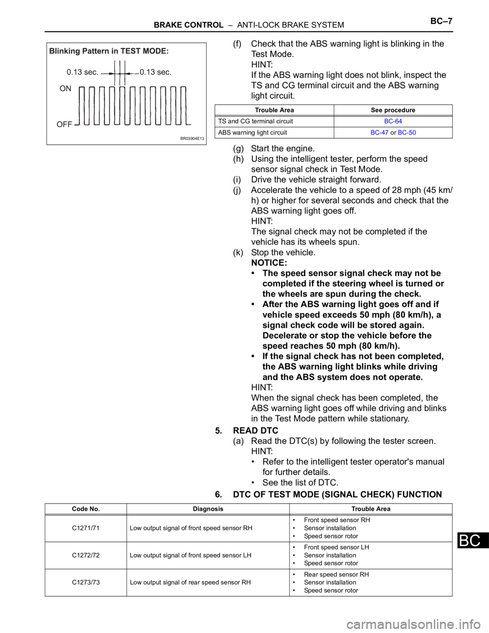
(f) Check that the ABS warning light is blinking in the
Test Mode.
HINT:
If the ABS warning light does not blink, inspect the
TS and CG terminal circuit and the ABS warning
light circuit.
(g) Start the engine.
(h) Using the intelligent tester, perform the speed
sensor signal check in Test Mode.
(i) Drive the vehicle straight forward.
(j) Accelerate the vehicle to a speed of 28 mph (45 km/
h) or higher for several seconds and check that the
ABS warning light goes off.
HINT:
The signal check may not be completed if the
vehicle has its wheels spun.
(k) Stop the vehicle.
NOTICE:
• The speed sensor signal check may not be
completed if the steering wheel is turned or
the wheels are spun during the check.
• After the ABS warning light goes off and if
vehicle speed exceeds 50 mph (80 km/h), a
signal check code will be stored again.
Decelerate or stop the vehicle before the
speed reaches 50 mph (80 km/h).
• If the signal check has not been completed,
the ABS warning light blinks while driving
and the ABS system does not operate.
HINT:
When the signal check has been completed, the
ABS warning light goes off while driving and blinks
in the Test Mode pattern while stationary.
5. READ DTC
(a) Read the DTC(s) by following the tester screen.
HINT:
• Refer to the intelligent tester operator's manual
for further details.
• See the list of DTC.
6. DTC OF TEST MODE (SIGNAL CHECK) FUNCTION
BR03904E13
Trouble Area See procedure
TS and CG terminal circuitBC-64
ABS warning light circuitBC-47 or BC-50
Code No. Diagnosis Trouble Area
C1271/71 Low output signal of front speed sensor RH• Front speed sensor RH
• Sensor installation
• Speed sensor rotor
C1272/72 Low output signal of front speed sensor LH• Front speed sensor LH
• Sensor installation
• Speed sensor rotor
C1273/73 Low output signal of rear speed sensor RH• Rear speed sensor RH
• Sensor installation
• Speed sensor rotor
Page 184 of 3000

BC–8BRAKE CONTROL – ANTI-LOCK BRAKE SYSTEM
BC
HINT:
The codes in this table are output only in Test Mode
(signal check).
C1274/74 Low output signal of rear speed sensor LH• Rear speed sensor LH
• Sensor installation
• Speed sensor rotor
C1275/75Abnormal change in output signal of front speed sensor
RHSpeed sensor rotor
C1276/76Abnormal change in output signal of front speed sensor
LHSpeed sensor rotor
C1277/77Abnormal change in output signal of rear speed sensor
RHSpeed sensor rotor
C1278/78Abnormal change in output signal of rear speed sensor
LHSpeed sensor rotor Code No. Diagnosis Trouble Area
Page 197 of 3000

SS–10SERVICE SPECIFICATIONS – 2GR-FE ENGINE MECHANICAL
SS
TORQUE SPECIFICATIONS
Part Tightened N*m kgf*cm ft.*lbf
Ignition coil assembly x Cylinder head cover sub-assembly 10 102 7
No. 1 engine hanger x Cylinder head sub-assembly RH 33 337 24
No. 2 engine hanger x Cylinder head sub-assembly LH 33 337 24
Engine mounting bracket RH x Cylinder block sub-assembly 54 551 40
No. 1 oil level gauge guide x Cylinder head sub-assembly 21 214 15
No. 2 oil level gauge guide x Cylinder block sub-assembly 21 214 15
No. 2 idler pulley sub-assembly x Timing chain cover sub-assembly 43 438 32
V-ribbed belt tensioner assembly x Cylinder block sub-assembly 43 438 32
Intake manifold x Cylinder head sub-assembly 21 214 15
Exhaust manifold sub-assembly RH x Cylinder head sub-assembly
RH21 214 15
Exhaust manifold sub-assembly LH x Cylinder head sub-assembly LH 21 214 15
Drive plate & ring gear sub-assembly x Crankshaft 83 850 61
Air cleaner case sub-assembly x Body 5.0 51 44 in.*lbf
Air cleaner case sub-assembly x Air cleaner bracket 5.0 51 44 in.*lbf
Engine coolant temperature x water by-pass joint RR 20 200 14
Engine assembly with Transaxle x Body A 85 867 63
B 32 329 24
No. 2 manifold stay x Exhaust manifold sub-assembly LH 34 347 25
No. 2 manifold stay x Cylinder block sub-assembly 34 347 25
No. 1 air cleaner inlet x Body 5.0 51 44 in.*lbf
No. 2 air cleaner inlet x Body 5.0 51 44 in.*lbf
Battery clamp x Body Bolt 5.5 56 49 in.*lbf
Nut 5.5 56 49 in.*lbf
Throttle body bracket x Intake air surge tank assembly 21 214 15
Throttle body bracket x Cylinder head cover sub-assembly RH 21 21415
No. 1 surge tank stay x Intake air surge tank assembly 21 214 15
No. 1 surge tank stay x Cylinder head cover sub-assembly RH 21 21415
No. 1 cowl top to cowl brace inner x Body 7.5 76 66 in.*lbf
No. 1 cowl top to cowl brace inner x Front outer cowl top panel sub-
assembly7.5 76 66 in.*lbf
Front outer cowl top panel sub-assembly x Body 7.5 76 66 in.*lbf
Fuel pump resistor x Front outer cowl top panel sub-assembly 7.576 66 in.*lbf
Radio setting condenser x Cylinder head cover sub-assembly RH 10102 7
Radio setting condense x Cylinder head cover sub-assembly LH 10 102 7
Intake air resonator sub-assembly x Body 5.0 51 44 in.*lbf
Air cleaner bracket x Body 7.8 80 69 in.*lbf
No. 1 vacuum switching valve assembly x Cylinder head cover sub-
assembly10 102 7
Engine mounting bracket RR x Cylinder block sub-assembly 64 650 47
Steering intermediate shaft x Steering gear 35 360 26
Stabilizer link x Shock absorber 74 755 55
Tie rod assembly x Steering gear 49 500 36
Front speed sensor x Front axle 8.0 85 71 in.*lbf
Front axle hub nut x Front drive shaft 294 2998 217
Cooler compressor assembly x V-ribbed belt tensioner 25 250 18
Cooler compressor assembly x Discharge hose sub-assembly 5.4 55 48 in.*lbf
Cooler compressor assembly x Suction hose sub-assembly 5.4 55 48 in.*lbf