2007 TOYOTA SIENNA sensor
[x] Cancel search: sensorPage 330 of 3000

ES–2622GR-FE ENGINE CONTROL SYSTEM – SFI SYSTEM
ES
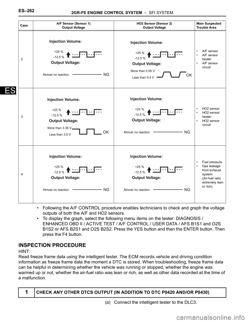
• Following the A/F CONTROL procedure enables technicians to check and graph the voltage
outputs of both the A/F and HO2 sensors.
• To display the graph, select the following menu items on the tester: DIAGNOSIS /
ENHANCED OBD II / ACTIVE TEST / A/F CONTROL / USER DATA / AFS B1S1 and O2S
B1S2 or AFS B2S1 and O2S B2S2. Press the YES button and then the ENTER button. Then
press the F4 button.
INSPECTION PROCEDURE
HINT:
Read freeze frame data using the intelligent tester. The ECM records vehicle and driving condition
information as freeze frame data the moment a DTC is stored. When troubleshooting, freeze frame data
can be helpful in determining whether the vehicle was running or stopped, whether the engine was
warmed up or not, whether the air-fuel ratio was lean or rich, as well as other data recorded at the time of
a malfunction.
(a) Connect the intelligent tester to the DLC3.
2• A/F sensor
• A/F sensor
heater
• A/F sensor
circuit
3• HO2 sensor
• HO2 sensor
heater
• HO2 sensor
circuit
4•Fuel pressure
• Gas leakage
from exhaust
system
(Air-fuel ratio
extremely lean
or rich)
1CHECK ANY OTHER DTCS OUTPUT (IN ADDITION TO DTC P0420 AND/OR P0430)
CaseA/F Sensor (Sensor 1)
Output VoltageHO2 Sensor (Sensor 2)
Output VoltageMain Suspected
Trouble Area
Page 331 of 3000

2GR-FE ENGINE CONTROL SYSTEM – SFI SYSTEMES–263
ES
(b) Turn the ignition switch to the ON position and turn the
tester on.
(c) Select the following menu items: DIAGNOSIS /
ENHANCED OBD II / DTC INFO / CURRENT CODES.
(d) Read the DTCs.
Result
HINT:
If any DTCs other than P0420 or P0430 are output,
troubleshoot those DTCs first.
B
A
(a) Connect the intelligent tester to the DLC3.
(b) Start the engine and turn the tester on.
(c) Warm up the engine at an engine speed of 2500 rpm for
approximately 90 seconds.
(d) Select the following menu items on the tester:
DIAGNOSIS / ENHANCED OBD II / ACTIVE TEST / A/F
CONTROL.
(e) Perform the A/F CONTROL operation with the engine in
an idling condition (press the RIGHT or LEFT button to
change the fuel injection volume).
(f) Monitor the voltage outputs of the A/F and HO2 sensors
(AFS B1S1 and O2S B1S2 or AFS B2S1 and O2S
B2S2) displayed on the tester.
HINT:
• The A/F CONTROL operation lowers the fuel injection
volume by 12.5% or increases the injection volume by
25%.
• Each sensor reacts in accordance with increases and
decreases in the fuel injection volume.
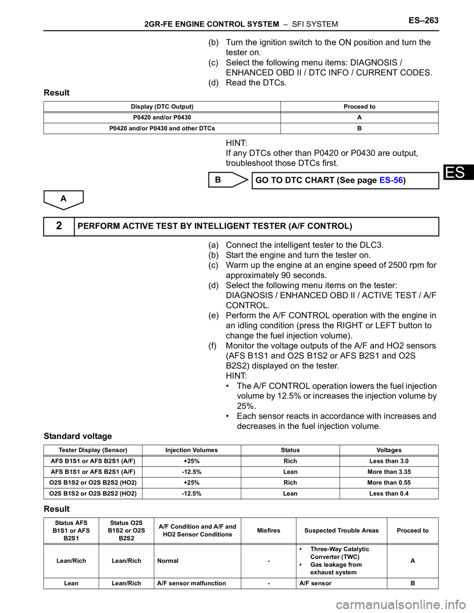
Standard voltage
Result
Display (DTC Output) Proceed to
P0420 and/or P0430 A
P0420 and/or P0430 and other DTCs B
GO TO DTC CHART (See page ES-56)
2PERFORM ACTIVE TEST BY INTELLIGENT TESTER (A/F CONTROL)
Tester Display (Sensor) Injection Volumes Status Voltages
AFS B1S1 or AFS B2S1 (A/F) +25% Rich Less than 3.0
AFS B1S1 or AFS B2S1 (A/F) -12.5% Lean More than 3.35
O2S B1S2 or O2S B2S2 (HO2) +25% Rich More than 0.55
O2S B1S2 or O2S B2S2 (HO2) -12.5% Lean Less than 0.4
Status AFS
B1S1 or AFS
B2S1Status O2S
B1S2 or O2S
B2S2A/F Condition and A/F and
HO2 Sensor ConditionsMisfires Suspected Trouble Areas Proceed to
Lean/Rich Lean/Rich Normal -• Three-Way Catalytic
Converter (TWC)
• Gas leakage from
exhaust systemA
Lean Lean/Rich A/F sensor malfunction - A/F sensor B
Page 332 of 3000

ES–2642GR-FE ENGINE CONTROL SYSTEM – SFI SYSTEM
ES
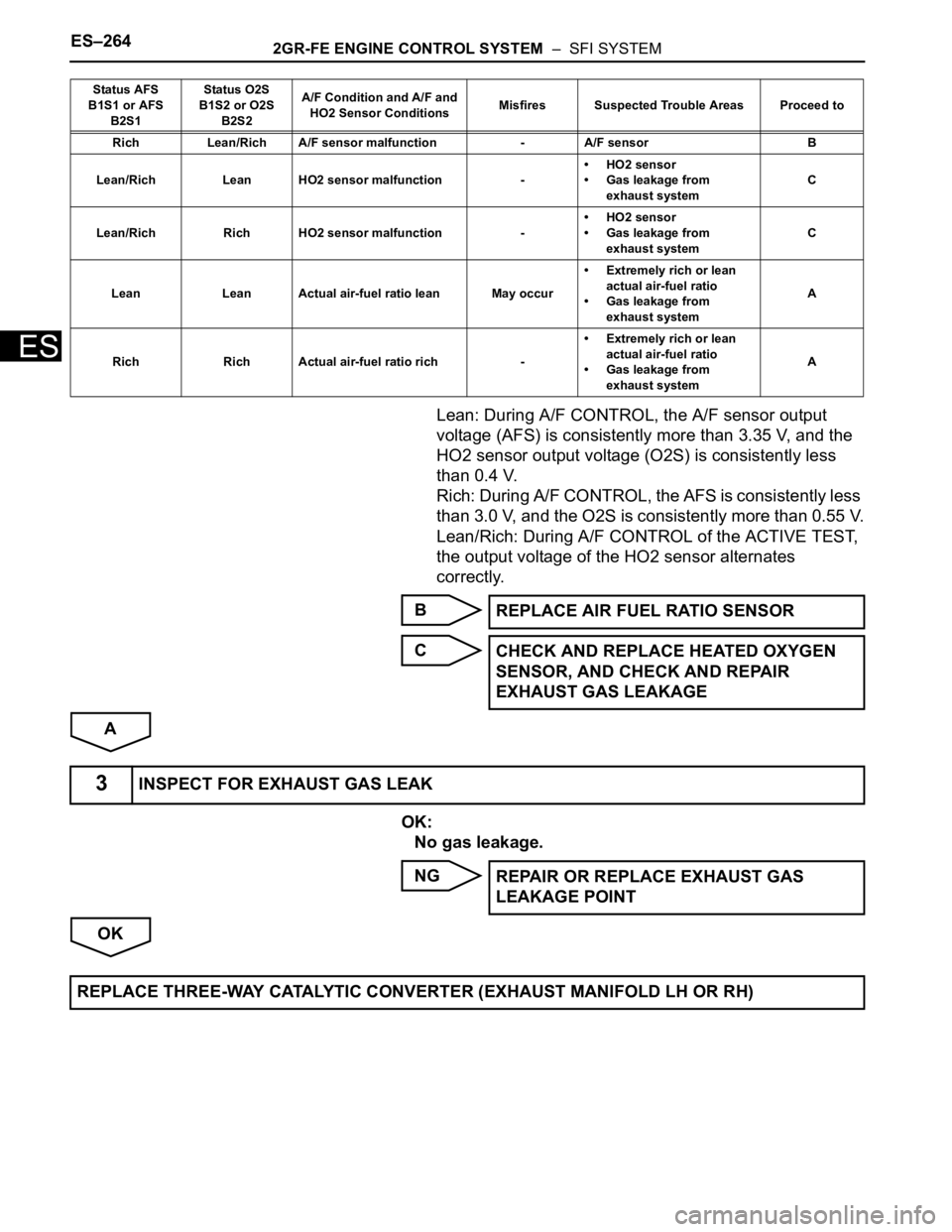
Lean: During A/F CONTROL, the A/F sensor output
voltage (AFS) is consistently more than 3.35 V, and the
HO2 sensor output voltage (O2S) is consistently less
than 0.4 V.
Rich: During A/F CONTROL, the AFS is consistently less
than 3.0 V, and the O2S is consistently more than 0.55 V.
Lean/Rich: During A/F CONTROL of the ACTIVE TEST,
the output voltage of the HO2 sensor alternates
correctly.
B
C
A
OK:
No gas leakage.
NG
OK
Rich Lean/Rich A/F sensor malfunction - A/F sensor B
Lean/Rich Lean HO2 sensor malfunction -• HO2 sensor
• Gas leakage from
exhaust systemC
Lean/Rich Rich HO2 sensor malfunction -• HO2 sensor
• Gas leakage from
exhaust systemC
Lean Lean Actual air-fuel ratio lean May occur• Extremely rich or lean
actual air-fuel ratio
• Gas leakage from
exhaust systemA
Rich Rich Actual air-fuel ratio rich -• Extremely rich or lean
actual air-fuel ratio
• Gas leakage from
exhaust systemA Status AFS
B1S1 or AFS
B2S1Status O2S
B1S2 or O2S
B2S2A/F Condition and A/F and
HO2 Sensor ConditionsMisfires Suspected Trouble Areas Proceed to
REPLACE AIR FUEL RATIO SENSOR
CHECK AND REPLACE HEATED OXYGEN
SENSOR, AND CHECK AND REPAIR
EXHAUST GAS LEAKAGE
3INSPECT FOR EXHAUST GAS LEAK
REPAIR OR REPLACE EXHAUST GAS
LEAKAGE POINT
REPLACE THREE-WAY CATALYTIC CONVERTER (EXHAUST MANIFOLD LH OR RH)
Page 349 of 3000

2GR-FE ENGINE CONTROL SYSTEM – SFI SYSTEMES–23
ES
2. ACCESS MONITOR RESULT
(a) Select the following menus on the intelligent tester:
DIAGNOSIS, ENHANCED OBDII, MONITOR INFO
and MONITOR RESULT. The monitor status
appears after the component name.
• INCMP: The component has not been monitored
yet.
• PASS: The component is functioning normally.
• FAIL: The component is malfunctioning.
(b) Confirm that the component is either PASS or FAIL.
(c) Select the component and press ENTER. The
accuracy test value appears if the monitor status is
either PASS or FAIL.
HINT:
The monitor result might be PASS on rare
occasions even if the Malfunction Indicator Lamp
(MIL) is illuminated. This indicates that the system
was malfunctioning in the previous driving cycle.
This might be caused by an intermittent problem.
3. CHECK COMPONENT STATUS
(a) Compare the test value with the minimum test limit
(MIN LIMIT) and maximum test limit (MAX LIMIT).
(b) If the test value is between the minimum test limit
and maximum test limit, the component is
functioning normally. If not, the component is
malfunctioning. The test value is usually significantly
higher or lower than the test limit. If the test value is
on the borderline of the test limit, the component will
malfunction in the near future.
HINT:
The monitor result might be PASS on rare occasions even if
the Malfunction Indicator Lamp (MIL) is illuminated. This
indicates that the system was malfunctioning in the previous
driving cycle. This might be caused by an intermittent
problem.
4. MONITOR RESULT INFORMATION
If you use a generic scan tool, multiply the test value by
the scaling value listed below.
A/F Sensor Bank 1
HO2S Bank 1 Sensor 2
A/F Sensor Bank 2
Monitor ID Test ID Scaling Unit Description
$01 $8E Multiply by 0.0003 No dimension A/F sensor deterioration level
$01 $91 Multiply by 0.004 mA A/F sensor current
Monitor ID Test ID Scaling Unit Description
$02 $07 Multiply by 0.001 V Minimum sensor voltage
$02 $08 Multiply by 0.001 V Maximum sensor voltage
$02 $8F Multiply by 0.003 g Maximum oxygen storage capacity
Monitor ID Test ID Scaling Unit Description
$05 $8E Multiply by 0.0003 No dimension A/F sensor deterioration level
$05 $91 Multiply by 0.004 mA A/F sensor current
Page 350 of 3000

ES–242GR-FE ENGINE CONTROL SYSTEM – SFI SYSTEM
ES
HO2S Bank 2 Sensor 2
Catalyst-Bank 1
Catalyst-Bank 2
EVAP
Misfire
Monitor ID Test ID Scaling Unit Description
$06 $07 Multiply by 0.001 V Minimum sensor voltage
$06 $08 Multiply by 0.001 V Maximum sensor voltage
$06 $8F Multiply by 0.003 g Maximum oxygen storage capacity
Monitor ID Test ID Scaling Unit Description
$21 $A9 Multiply by 0.003 No dimension Oxygen storage capacity of catalyst-bank 1
Monitor ID Test ID Scaling Unit Description
$22 $A9 Multiply by 0.003 No dimension Oxygen storage capacity of catalyst-bank 2
Monitor ID Test ID Scaling Unit Description
$3D $C9 Multiply by 0.001 kPa Test value for small leak (P0456)
$3D $CA Multiply by 0.001 kPa Test value for gross leak (P0455)
$3D $CB Multiply by 0.001 kPa Test value for leak detection pump OFF stuck (P2401)
$3D $CD Multiply by 0.001 kPa Test value for leak detection pump ON stuck (P2402)
$3D $CE Multiply by 0.001 kPa Test value for vent valve OFF stuck (P2420)
$3D $CF Multiply by 0.001 kPa Test value for vent valve ON stuck (P2419)
$3D $D0 Multiply by 0.001 kPa Test value for reference orifice low flow (P043E)
$3D $D1 Multiply by 0.001 kPa Test value for reference orifice high flow (P043F)
$3D $D4 Multiply by 0.001 kPa Test value for purge VSV close stuck (P0441)
$3D $D5 Multiply by 0.001 kPa Test value for purge VSV open stuck (P0441)
$3D $D7 Multiply by 0.001 kPa Test value for purge flow insufficient (P0441)
Monitor ID Test ID Scaling Unit Description
$A1 $0B Multiply by 1 TimeExponential Weighted Moving Average (EWMA) misfire for all
cylinders: Misfire counts for last ten driving cycles-Total
$A1 $0C Multiply by 1 TimeMisfire rate for all cylinders: Misfire counts for last/current driving
cycles-Total
$A2 $0B Multiply by 1 TimeEWMA misfire for cylinder 1: Misfire counts for last ten driving cycles-
To t a l
$A2 $0C Multiply by 1 TimeMisfire rate for cylinder 1: Misfire counts for last/current driving cycle-
To t a l
$A3 $0B Multiply by 1 TimeEWMA misfire for cylinder 2: Misfire counts for last ten driving cycles-
To t a l
$A3 $0C Multiply by 1 TimeMisfire rate for cylinder 2: Misfire counts for last/current driving cycle-
To t a l
$A4 $0B Multiply by 1 TimeEWMA misfire for cylinder 3: Misfire counts for last ten driving cycles-
To t a l
$A4 $0C Multiply by 1 TimeMisfire rate for cylinder 3: Misfire counts for last/current driving cycle-
To t a l
$A5 $0B Multiply by 1 TimeEWMA misfire for cylinder 4: Misfire counts for last ten driving cycles-
To t a l
$A5 $0C Multiply by 1 TimeMisfire rate for cylinder 4: Misfire counts for last/current driving cycle-
To t a l
$A6 $0B Multiply by 1 TimeEWMA misfire for cylinder 5: Misfire counts for last ten driving cycles-
To t a l
$A6 $0C Multiply by 1 TimeMisfire rate for cylinder 5: Misfire counts for last/current driving cycle-
To t a l
$A7 $0B Multiply by 1 TimeEWMA misfire for cylinder 6: Misfire counts for last ten driving cycles-
To t a l
Page 351 of 3000

2GR-FE ENGINE CONTROL SYSTEM – SFI SYSTEMES–25
ES
Rear Oxygen Sensor Heater
$A7 $0C Multiply by 1 TimeMisfire rate for cylinder 6: Misfire counts for last/current driving cycle-
To t a l
Monitor ID Test ID Scaling Unit Description
$42 $91 Multiply by 0.001 Ohm Oxygen sensor heater resistance bank 1 sensor 2
$46 $91 Multiply by 0.004 Ohm Oxygen sensor heater resistance bank 2 sensor 2 Monitor ID Test ID Scaling Unit Description
Page 353 of 3000

2GR-FE ENGINE CONTROL SYSTEM – SFI SYSTEMES–27
ES
Contents:
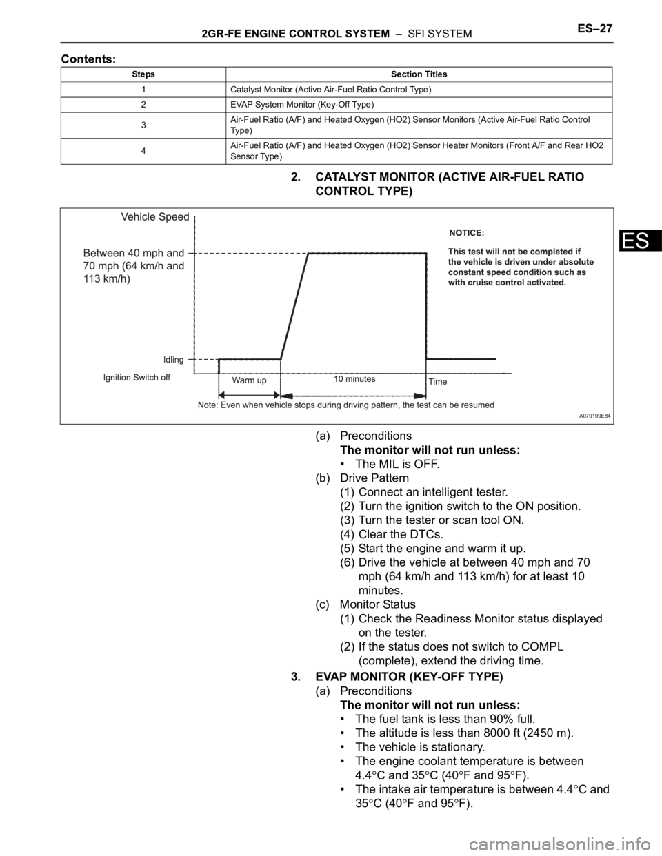
2. CATALYST MONITOR (ACTIVE AIR-FUEL RATIO
CONTROL TYPE)
(a) Preconditions
The monitor will not run unless:
• The MIL is OFF.
(b) Drive Pattern
(1) Connect an intelligent tester.
(2) Turn the ignition switch to the ON position.
(3) Turn the tester or scan tool ON.
(4) Clear the DTCs.
(5) Start the engine and warm it up.
(6) Drive the vehicle at between 40 mph and 70
mph (64 km/h and 113 km/h) for at least 10
minutes.
(c) Monitor Status
(1) Check the Readiness Monitor status displayed
on the tester.
(2) If the status does not switch to COMPL
(complete), extend the driving time.
3. EVAP MONITOR (KEY-OFF TYPE)
(a) Preconditions
The monitor will not run unless:
• The fuel tank is less than 90% full.
• The altitude is less than 8000 ft (2450 m).
• The vehicle is stationary.
• The engine coolant temperature is between
4.4
C and 35C (40F and 95F).
• The intake air temperature is between 4.4
C and
35
C (40F and 95F).
Steps Section Titles
1 Catalyst Monitor (Active Air-Fuel Ratio Control Type)
2 EVAP System Monitor (Key-Off Type)
3Air-Fuel Ratio (A/F) and Heated Oxygen (HO2) Sensor Monitors (Active Air-Fuel Ratio Control
Ty p e )
4Air-Fuel Ratio (A/F) and Heated Oxygen (HO2) Sensor Heater Monitors (Front A/F and Rear HO2
Sensor Type)
A079199E84
Page 354 of 3000

ES–282GR-FE ENGINE CONTROL SYSTEM – SFI SYSTEM
ES
• Vehicle was driven in the city area (or on free-
way) for 10 minutes or more.
(b) Monitor Conditions
(1) Turn the ignition switch off and wait for 6 hours.
HINT:
Do not start the engine until checking Readiness
Monitor status. If the engine is started, the step
described above must be repeated.
(c) Monitor Status
(1) Connect an intelligent tester to the DLC3.
(2) Turn the ignition switch to the ON position.
(3) Turn the tester or scan tool ON.
(4) Check the Readiness Monitor status displayed
on the tester or scan tool.
If the status does not switch to COMPL
(complete), restart the engine, make sure that
the preconditions have been met, and then
perform the Monitor Conditions again.
4. A/F SENSOR AND HO2S MONITORS
(a) Preconditions
The monitor will not run unless:
• 2 minutes or more have elapsed since the engine
was started.
• The Engine Coolant Temperature (ECT) is 75
C
(167
F) or more.
• Cumulative driving time at a vehicle speed of 30
mph (48 km/h) or more exceeds 6 minutes.
• Air-fuel ratio feedback control is performed.
• Fuel-cut control is performed for 8 seconds or
more (for the Rear HO2 Sensor Monitor).
(b) Drive Pattern for front A/F sensor and HO2 sensor.
(1) Connect an intelligent tester to the DLC3.
(2) Turn the ignition switch to the ON position.
(3) Turn the tester ON.
(4) Clear the DTCs.
(5) Start the engine, and warm it up until the ECT
reaches 75
C (167F) or higher.
(6) Drive the vehicle at 38 mph (60 km/h) or more
for at least 10 minutes.
(7) Change the transmission to the 2nd gear.
(8) Accelerate the vehicle to 40 mph (64 km/h) or
more by depressing the accelerator pedal for at
least 10 seconds (Procedure "A").
(9) Soon after performing procedure "A" above,
release the accelerator pedal for at least 4
seconds without depressing the brake pedal, in
order to execute fuel-cut control (Procedure "B").
(10) Allow the vehicle to decelerate until the vehicle
speed declines to less than 6 mph (10 km/h)
(Procedure "C").
(11) Repeat procedures from "A" through "C" above
at least 3 times in one driving cycle.