2007 TOYOTA SIENNA sensor
[x] Cancel search: sensorPage 41 of 3000

EM–422GR-FE ENGINE MECHANICAL – ENGINE ASSEMBLY
EM
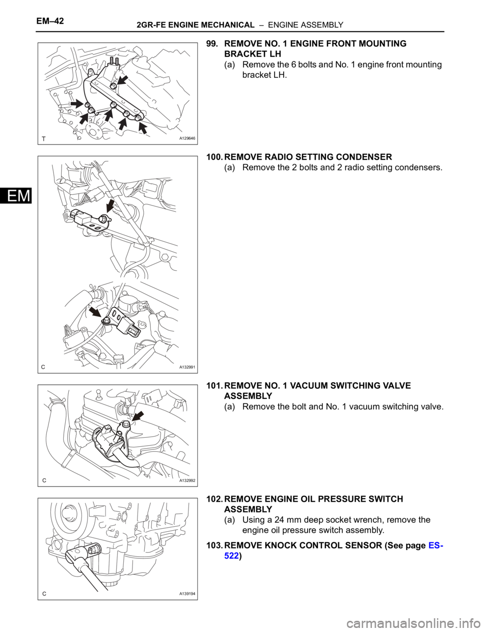
99. REMOVE NO. 1 ENGINE FRONT MOUNTING
BRACKET LH
(a) Remove the 6 bolts and No. 1 engine front mounting
bracket LH.
100. REMOVE RADIO SETTING CONDENSER
(a) Remove the 2 bolts and 2 radio setting condensers.
101. REMOVE NO. 1 VACUUM SWITCHING VALVE
ASSEMBLY
(a) Remove the bolt and No. 1 vacuum switching valve.
102. REMOVE ENGINE OIL PRESSURE SWITCH
ASSEMBLY
(a) Using a 24 mm deep socket wrench, remove the
engine oil pressure switch assembly.
103. REMOVE KNOCK CONTROL SENSOR (See page ES-
522)
A129646
A132991
A132992
A139194
Page 50 of 3000

IN–38INTRODUCTION – HOW TO TROUBLESHOOT ECU CONTROLLED SYSTEMS
IN
HINT:
• In troubleshooting, confirm that the problem symptoms
have been accurately identified. Preconceptions should be
discarded in order to make an accurate judgment. To
clearly understand what the problem symptoms are, it is
extremely important to ask the customer about the
problem and the conditions at the time the malfunction
occurred.
• Gather as much information as possible for reference.
Past problems that seem unrelated may also help in some
cases.
• The following 5 items are important points in the problem
analysis:
3. SYMPTOM CONFIRMATION AND DIAGNOSTIC
TROUBLE CODE
HINT:
The diagnostic system in the SIENNA has various
functions.
• The first function is the Diagnostic Trouble Code
(DTC) check. A DTC is a code stored in the ECU
memory whenever a malfunction in the signal circuits
to the ECU occurs. In a DTC check, a previous
malfunction's DTC can be checked by a technician
during troubleshooting.
• Another function is the Input Signal Check, which
checks if the signals from various switches are sent to
the ECU correctly.
By using these functions, the problem areas can be
narrowed down and troubleshooting is more effective.
Diagnostic functions are incorporated in the following
system in the SIENNA.
What Vehicle model, system name
When Date, time, occurrence frequency
Where Road conditions
Under what conditions? Running conditions, driving conditions, weather conditions
How did it happen? Problem symptoms
SystemSYMPTOM CONFIRMATION AND DIAGNOSTIC TROUBLE CODE
DTC Check
(Normal Mode)DTC Check
(Check Mode)Sensor Check/
Test Mode
(Input Signal
Check)Data List Active Test
2GR-FE SFI System
X
U151E Automatic Transaxle SystemX
U151F Automatic Transaxle SystemX
Tire pressure warning systemXX
Anti-lock Brake System
X
Vehicle Stability Control SystemX
Air Conditioning System (for Manual Air
Conditioning System)XXXXX
Air Conditioning System (for Automatic Air
Conditioning System)
XX
Airbag SystemXX
Occupant Classification System
XXX
Page 51 of 3000

INTRODUCTION – HOW TO TROUBLESHOOT ECU CONTROLLED SYSTEMSIN–39
IN
• In the DTC check, it is very important to determine
whether the problem indicated by the DTC either: 1)
still occurs, or 2) occurred in the past but has returned
to normal. In addition, the DTC should be compared
to the problem symptom to see if they are related. For
this reason, DTCs should be checked before and after
confirmation of symptoms (i.e., whether or not
problem symptoms exist) to determine current system
conditions, as shown in the flowchart below.
• Never skip the DTC check. Failing to check DTCs
may, depending on the case, result in unnecessary
troubleshooting for systems operating normally or
lead to repairs not related to the problem. Follow the
procedures listed in the flowchart in the correct order.
Theft Deterrent System XXXXX
Engine Immobiliser System
XX
Cruise Control SystemXXX
Dynamic Laser Cruise Control System
XXX
Lighting System
XX
Wiper and Washer SystemXXXXX
Power Door Lock Control System X X X
Wireless Door Lock Control SystemXX
Key Reminder Warning System X X XX
Meter / Gauge System X X X
Audio and Visual SystemXXXX
Rear Seat Entertainment System XXXXX
Navigation System
XXXX
Clearance Sonar SystemXXXXX
Rear View Monitor System XXXXX
Power Window Control System (with Jam
Protection Function)XXX
Power Window Control System (without Jam
Protection Function)XXXXX
Power Mirror Control System (with Memory) X X X
Power Mirror Control System (without Memory)XXXXX
Front Power Seat Control System X X X
Rear No. 2 Seat Assembly (with Power Stowing
Function)XXXXX
Window Deogger SystemXXXXX
Power Slide Door System
XX
Slide Door Closer System X X X
Back Door Closer SystemXX
Power Back Door SystemXX
Sliding Roof System XXXXX
Multiplex Communication System XXXXX
CAN Communication System XXXXXSystemSYMPTOM CONFIRMATION AND DIAGNOSTIC TROUBLE CODE
DTC Check
(Normal Mode)DTC Check
(Check Mode)Sensor Check/
Test Mode
(Input Signal
Check)Data List Active Test
Page 54 of 3000

IN–42INTRODUCTION – HOW TO TROUBLESHOOT ECU CONTROLLED SYSTEMS
IN
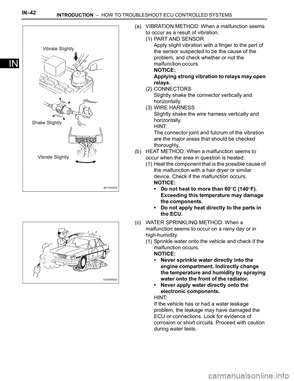
(a) VIBRATION METHOD: When a malfunction seems
to occur as a result of vibration.
(1) PART AND SENSOR
Apply slight vibration with a finger to the part of
the sensor suspected to be the cause of the
problem, and check whether or not the
malfunction occurs.
NOTICE:
Applying strong vibration to relays may open
relays.
(2) CONNECTORS
Slightly shake the connector vertically and
horizontally.
(3) WIRE HARNESS
Slightly shake the wire harness vertically and
horizontally.
HINT:
The connector joint and fulcrum of the vibration
are the major areas that should be checked
thoroughly.
(b) HEAT METHOD: When a malfunction seems to
occur when the area in question is heated.
(1) Heat the component that is the possible cause of
the malfunction with a hair dryer or similar
device. Check if the malfunction occurs.
NOTICE:
• Do not heat to more than 60
C (140F).
Exceeding this temperature may damage
the components.
• Do not apply heat directly to the parts in
the ECU.
(c) WATER SPRINKLING METHOD: When a
malfunction seems to occur on a rainy day or in
high-humidity.
(1) Sprinkle water onto the vehicle and check if the
malfunction occurs.
NOTICE:
• Never sprinkle water directly into the
engine compartment. Indirectly change
the temperature and humidity by spraying
water onto the front of the radiator.
• Never apply water directly onto the
electronic components.
HINT:
If the vehicle has or had a water leakage
problem, the leakage may have damaged the
ECU or connections. Look for evidence of
corrosion or short circuits. Proceed with caution
during water tests.B071602E03
D025085E02
Page 56 of 3000

IN–44INTRODUCTION – HOW TO TROUBLESHOOT ECU CONTROLLED SYSTEMS
IN
Inspection Procedures Use the inspection procedures to determine if the circuit is normal or
abnormal. If abnormal, use the inspection procedures to determine
whether the problem is located in the sensors, actuators, wire
harnesses or ECU.
Indicates the condition of the connector of the ECU during the check Connector being checked is connected.
Connections of tester are indicated by (+) or (-) after the terminal
name.
Connector being checked is disconnected.
The inspections between a connector and body ground, information
about the body ground is not shown in the illustration. Item Description
Page 57 of 3000

IN–50INTRODUCTION – TERMS
IN
GLOSSARY OF SAE AND TOYOTA
TERMS
This glossary lists all SAE-J1930 terms and abbreviations
used in this manual in compliance with SAE
recommendations, as well as their TOYOTA equivalents.
SAE
ABBREVIATIONSSAE TERMSTOYOTA TERMS
( )-ABBREVIATIONS
A/C Air Conditioning Air Conditioner
ACL Air Cleaner Air Cleaner, A/CL
AIR Secondary Air Injection Air Injection (AI)
AP Accelerator Pedal -
B+ Battery Positive Voltage +B, Battery Voltage
BARO Barometric Pressure HAC
CAC Charge Air Cooler Intercooler
CARB Carburetor Carburetor
CFI Continuous Fuel Injection -
CKP Crankshaft Position Crank Angle
CL Closed Loop Closed Loop
CMP Camshaft Position Cam Angle
CPP Clutch Pedal Position -
CTOX Continuous Trap Oxidizer -
CTP Closed Throttle Position LL ON, Idle ON
DFI Direct Fuel Injection Direct Injection (DI./INJ)
DI Distributor Ignition -
DLC3 Data Link Connector 3 OBD II Diagnostic Connector
DTC Diagnostic Trouble Code Diagnostic Trouble Code
DTM Diagnostic Test Mode -
ECL Engine Coolant Level -
ECM Engine Control Module Engine Electronic Control Unit (ECU)
ECT Engine Coolant Temperature Coolant Temperature, Water Temperature (THW)
EEPROM Electrically Erasable Programmable Read Only MemoryElectrically Erasable Programmable Read Only
Memory (EEPROM), Erasable Programmable Read
Only Memory (EPROM)
EFE Early Fuel Evaporation Cold Mixture Heater (CMH), Heat Control Valve (HCV)
EGR Exhaust Gas Recirculation Exhaust Gas Recirculation (EGR)
EI Electronic Ignition Distributorless Ignition (DLI)
EM Engine Modification Engine Modification (EM)
EPROM Erasable Programmable Read Only Memory Programmable Read Only Memory (PROM)
EVAP Evaporative Emission Evaporative Emission Control (EVAP)
FC Fan Control -
FEEPROMFlash Electrically Erasable Programmable Read Only
Memory-
FEPROM Flash Erasable Programmable Read Only Memory -
FF Flexible Fuel -
FP Fuel Pump Fuel Pump
GEN Generator Alternator
GND Ground Ground (GND)
HO2S Heated Oxygen SensorHeated Oxygen Sensor (HO
2S)
IAC Idle Air Control Idle Speed Control (ISC)
IAT Intake Air Temperature Intake or Inlet Air Temperature
ICM Ignition Control Module -
Page 58 of 3000

INTRODUCTION – TERMSIN–51
IN
IFI Indirect Fuel Injection Indirect Injection (IDL)
IFS Inertia Fuel-Shutoff -
ISC Idle Speed Control -
KS Knock Sensor Knock Sensor
MAF Mass Airflow Air Flow Meter
MAP Manifold Absolute Pressure Manifold Pressure Intake Vacuum
MC Mixture ControlElectric Bleed Air Control Valve (EBCV)
Mixture Control Valve (MCV)
Electric Air Control Valve (EACV)
MDP Manifold Differential Pressure -
MFI Multiport Fuel Injection Electronic Fuel Injection (EFI)
MIL Malfunction Indicator Light Check Engine Light
MST Manifold Surface Temperature -
MVZ Manifold Vacuum Zone -
NVRAM Non-Volatile Random Access Memory -
O2S Oxygen SensorOxygen Sensor, O
2 Sensor (O2S)
OBD On-Board Diagnostic On-Board Diagnostic System (OBD)
OC Oxidation Catalytic Converter Oxidation Catalytic Convert (OC), CCo
OL Open Loop Open Loop
PAIR Pulsed Secondary Air Injection Air Suction (AS)
PCM Powertrain Control Module -
PNP Park/Neutral Position -
PROM Programmable Read Only Memory -
PSP Power Steering Pressure -
PTOX Periodic Trap OxidizerDiesel Particulate Filter (DPF)
Diesel Particulate Trap (DPT)
RAM Random Access Memory Random Access Memory (RAM)
RM Relay Module -
ROM Read Only Memory Read Only Memory (ROM)
RPM Engine Speed Engine Speed
SC Supercharger Supercharger
SCB Supercharger Bypass E-ABV
SFI Sequential Multiport Fuel Injection Electronic Fuel Injection (EFI), Sequential Injection
SPL Smoke Puff Limiter -
SRI Service Reminder Indicator -
SRT System Readiness Test -
ST Scan Tool -
TB Throttle Body Throttle Body
TBI Throttle Body Fuel InjectionSingle Point Injection
Central Fuel Injection (Ci)
TC Turbocharger Turbocharger
TCC Torque Converter Clutch Torque Converter
TCM Transmission Control Module Transmission ECU, ECT ECU
TP Throttle Position Throttle Position
TR Transmission Range -
TVV Thermal Vacuum ValveBimetallic Vacuum Switching Valve (BVSV)
Thermostatic Vacuum Switching Valve (TVSV)
TWC Three-Way Catalytic ConverterThree-Way Catalytic (TWC)
Manifold Converter
CC
RO
SAE
ABBREVIATIONSSAE TERMSTOYOTA TERMS
( )-ABBREVIATIONS
Page 59 of 3000

IN–52INTRODUCTION – TERMS
IN
TWC+OC Three-Way + Oxidation Catalytic ConverterCCR + CCo
VAF Volume Airflow Air Flow Meter
VR Voltage Regulator Voltage Regulator
VSS Vehicle Speed Sensor Vehicle Speed Sensor
WOT Wide Open Throttle Full Throttle
WU-OC Warm Up Oxidation Catalytic Converter -
WU-TWC Warm Up Three-Way Catalytic Converter -
3GR Third Gear -
4GR Fourth Gear -SAE
ABBREVIATIONSSAE TERMSTOYOTA TERMS
( )-ABBREVIATIONS