Page 95 of 3000
AX–168U151E AUTOMATIC TRANSAXLE – AUTOMATIC TRANSAXLE ASSEMBLY
AX
7. INSTALL TRANSMISSION CONTROL CABLE
BRACKET NO.1
(a) Install the control cable bracket No.1 with the 2
bolts.
Torque: 12 N*m (122 kgf*cm, 9 ft.*lbf)
8. CONNECT CONNECTORS
(a) Connect the transmission wire connector.
(b) Connect the park/neutral position switch connector.
(c) Connect the 2 speed sensor connectors.
9. INSTALL STARTER ASSEMBLY
(a) Install the starter assembly with the 2 bolts (1).
Torque: 37 N*m (377 kgf*cm, 27 ft.*lbf)
(b) Connect the connector (2).
(c) Connect the starter wire with the nut (3).
Torque: 9.8 N*m (100 kgf*cm, 87 in.*lbf)
10. CONNECT WIRE HARNESS
(a) Connect the wire harness with the bolt.
Torque: 13 N*m (133 kgf*cm, 10 ft.*lbf)
D030467
D030864E03
D030464E03
G025456
Page 97 of 3000

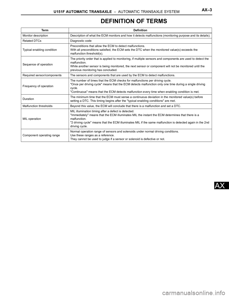
U151F AUTOMATIC TRANSAXLE – AUTOMATIC TRANSAXLE SYSTEMAX–3
AX
DEFINITION OF TERMS
Te r m D e f i n i t i o n
Monitor description Description of what the ECM monitors and how it detects malfunctions (monitoring purpose and its details).
Related DTCs Diagnostic code
Typical enabling conditionPreconditions that allow the ECM to detect malfunctions.
With all preconditions satisfied, the ECM sets the DTC when the monitored value(s) exceeds the
malfunction threshold(s).
Sequence of operationThe priority order that is applied to monitoring, if multiple sensors and components are used to detect the
malfunction.
While another sensor is being monitored, the next sensor or component will not be monitored until the
previous monitoring has concluded.
Required sensor/components The sensors and components that are used by the ECM to detect malfunctions.
Frequency of operationThe number of times that the ECM checks for malfunctions per driving cycle.
"Once per driving cycle" means that the ECM detects malfunction only one time during a single driving
cycle.
"Continuous" means that the ECM detects malfunction every time when enabling condition is met.
DurationThe minimum time that the ECM must sense a continuous deviation in the monitored value(s) before
setting a DTC. This timing begins after the "typical enabling conditions" are met.
Malfunction thresholds Beyond this value, the ECM will conclude that there is a malfunction and set a DTC.
MIL operationMIL illumination timing after a defect is detected.
"Immediately" means that the ECM illuminates MIL the instant the ECM determines that there is a
malfunction.
"2 driving cycle" means that the ECM illuminates MIL if the same malfunction is detected again in the 2nd
driving cycle.
Component operating rangeNormal operation range of sensors and solenoids under normal driving conditions.
Use these ranges as a reference.
They cannot be used to judge if a sensor or solenoid is defective or not.
Page 100 of 3000
U151F AUTOMATIC TRANSAXLE – AUTOMATIC TRANSAXLE ASSEMBLYAX–165
AX
7. REMOVE STARTER ASSEMBLY
(a) Disconnect the connector (1).
(b) Remove the nut (2) and disconnect the starter wire.
(c) Remove the 2 bolts (3) and starter assembly.
8. DISCONNECT CONNECTORS
(a) Disconnect the transmission wire connector.
(b) Disconnect the park/neutral position switch
connector.
(c) Disconnect the 2 speed sensor connectors.
9. REMOVE TRANSMISSION CONTROL CABLE
BRACKET NO.1
(a) Remove the bolt and automatic transmission oil
cooler tube clamp.
(b) Remove the 2 bolts and transmission control cable
bracket No.1.
10. REMOVE TRANSMISSION OIL FILLER TUBE SUB-
ASSEMBLY
(a) Remove the ATF level gauge.
(b) Disconnect the wire harnesses 2 clamps from the oil
filler tube.
(c) Remove the 2 bolts and oil filler tube.
(d) Remove the O-ring from the oil filler tube.
D030464E02
D030864E04
D030467
D030468
Page 105 of 3000
AX–170U151F AUTOMATIC TRANSAXLE – AUTOMATIC TRANSAXLE ASSEMBLY
AX
(c) Install the oil cooler tube clamp and bolt.
Torque: 5.5 N*m (56 kgf*cm, 49 in.*lbf)
(d) Using SST and a wrench, tighten the oil cooler inlet
tube No.1.
SST 09023-12701
Torque: 34 N*m (347 kgf*cm, 25 ft.*lbf)
8. INSTALL OIL COOLER OUTLET TUBE NO.1
(a) Using SST and a wrench, tighten the oil cooler
outlet tube No.1.
SST 09023-12701
Torque: 34 N*m (347 kgf*cm, 25 ft.*lbf)
9. INSTALL TRANSMISSION CONTROL CABLE
BRACKET NO.1
(a) Install the control cable bracket No.1 with the 2
bolts.
Torque: 12 N*m (122 kgf*cm, 9 ft.*lbf)
10. CONNECT CONNECTORS
(a) Connect the transmission wire connector.
(b) Connect the park/neutral position switch connector.
(c) Connect the 2 speed sensor connectors.
D030699
D030469E04
D030467
D030864E04
Page 108 of 3000
TF–10TRANSFER – TRANSFER ASSEMBLY
TF
6. INSTALL NO. 1 TRANSFER CASE PLUG
(a) Add oil up to 0 to 5 mm below the lower side of the
plug hole.
Oil quantity:
0.9 L (0.95 US qts, 0.71 lmp. qts)
HINT:
When adding oil, pour it slowly.
(b) Install the No. 1 transfer case plug with a new No. 1
gasket.
Torque: 49 N*m (500 kgf*cm, 36 ft.*lbf)
7. INSPECT AND ADJUST FRONT WHEEL ALIGNMENT
HINT:
(See page SP-4)
8. CHECK ABS SPEED SENSOR SIGNAL
HINT:
(See page BC-3)
Page 110 of 3000

DRIVE SHAFT – FRONT DRIVE SHAFTDS–5
DS
REMOVAL
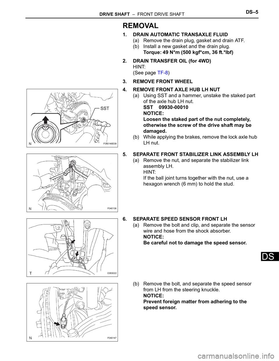
1. DRAIN AUTOMATIC TRANSAXLE FLUID
(a) Remove the drain plug, gasket and drain ATF.
(b) Install a new gasket and the drain plug.
Torque: 49 N*m (500 kgf*cm, 36 ft.*lbf)
2. DRAIN TRANSFER OIL (for 4WD)
HINT:
(See page TF-8)
3. REMOVE FRONT WHEEL
4. REMOVE FRONT AXLE HUB LH NUT
(a) Using SST and a hammer, unstake the staked part
of the axle hub LH nut.
SST 09930-00010
NOTICE:
Loosen the staked part of the nut completely,
otherwise the screw of the drive shaft may be
damaged.
(b) While applying the brakes, remove the lock axle hub
LH nut.
5. SEPARATE FRONT STABILIZER LINK ASSEMBLY LH
(a) Remove the nut, and separate the stabilizer link
assembly LH.
HINT:
If the ball joint turns together with the nut, use a
hexagon wrench (6 mm) to hold the stud.
6. SEPARATE SPEED SENSOR FRONT LH
(a) Remove the bolt and clip, and separate the sensor
wire and hose from the shock absorber.
NOTICE:
Be careful not to damage the speed sensor.
(b) Remove the bolt, and separate the speed sensor
from LH from the steering knuckle.
NOTICE:
Prevent foreign matter from adhering to the
speed sensor.
F040146E09
F040136
C083022
F040147
Page 111 of 3000

DS–6DRIVE SHAFT – FRONT DRIVE SHAFT
DS
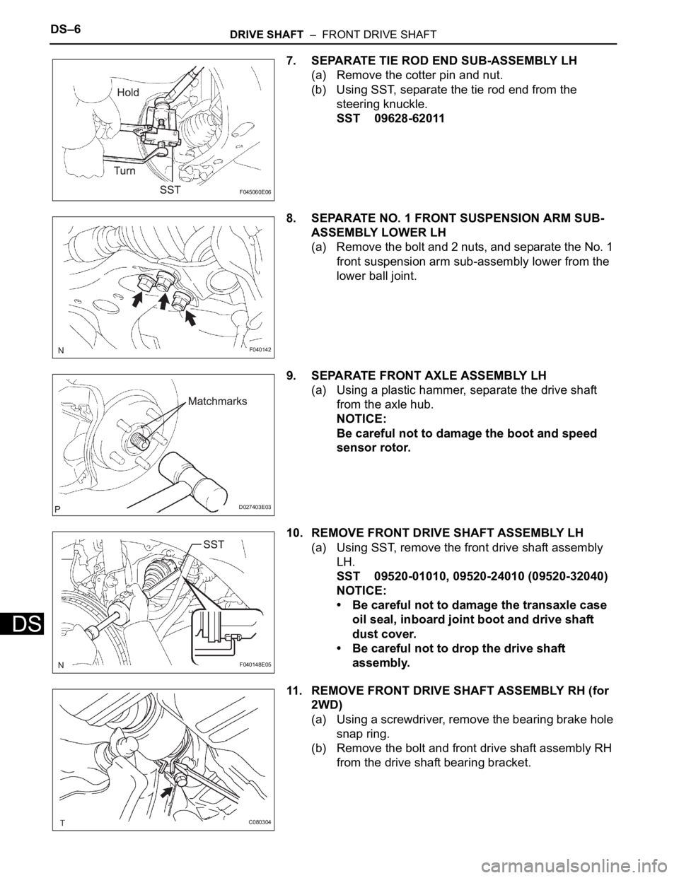
7. SEPARATE TIE ROD END SUB-ASSEMBLY LH
(a) Remove the cotter pin and nut.
(b) Using SST, separate the tie rod end from the
steering knuckle.
SST 09628-62011
8. SEPARATE NO. 1 FRONT SUSPENSION ARM SUB-
ASSEMBLY LOWER LH
(a) Remove the bolt and 2 nuts, and separate the No. 1
front suspension arm sub-assembly lower from the
lower ball joint.
9. SEPARATE FRONT AXLE ASSEMBLY LH
(a) Using a plastic hammer, separate the drive shaft
from the axle hub.
NOTICE:
Be careful not to damage the boot and speed
sensor rotor.
10. REMOVE FRONT DRIVE SHAFT ASSEMBLY LH
(a) Using SST, remove the front drive shaft assembly
LH.
SST 09520-01010, 09520-24010 (09520-32040)
NOTICE:
• Be careful not to damage the transaxle case
oil seal, inboard joint boot and drive shaft
dust cover.
• Be careful not to drop the drive shaft
assembly.
11. REMOVE FRONT DRIVE SHAFT ASSEMBLY RH (for
2WD)
(a) Using a screwdriver, remove the bearing brake hole
snap ring.
(b) Remove the bolt and front drive shaft assembly RH
from the drive shaft bearing bracket.
F045060E06
F040142
D027403E03
F040148E05
C080304
Page 163 of 3000
AH–6AXLE – FRONT AXLE HUB
AH
REMOVAL
HINT:
Replace the RH side using the same procedures as for the
LH side.
1. REMOVE FRONT WHEEL
2. REMOVE FRONT AXLE HUB LH NUT (See page DS-
5)
3. SEPARATE SPEED SENSOR FRONT LH (See page
DS-5)
4. SEPARATE FRONT DISC BRAKE CALIPER
ASSEMBLY LH
(a) Remove the 2 bolts and separate the front disc
brake caliper assembly LH from the steering
knuckle LH.
NOTICE:
Use a string or other device to keep the brake
caliper from hanging down.
5. REMOVE FRONT DISC
6. SEPARATE TIE ROD END SUB-ASSEMBLY LH (See
page DS-6)
7. SEPARATE FRONT SUSPENSION ARM SUB-
ASSEMBLY LOWER NO.1 LH (See page DS-6)
8. REMOVE FRONT AXLE ASSEMBLY LH
(a) Using a plastic hammer, separate the front drive
shaft assembly LH from the front axle hub sub-
assembly LH.
NOTICE:
Be careful not to damage the boot and ABS
speed sensor rotor.
(b) Remove the 2 bolts, nuts and steering knuckle LH
with the front axle nub sub-assembly LH.
C067088
D027403
C083023