Page 1352 of 3000
2GR-FE CHARGING – GENERATORCH–17
CH
24. REMOVE RADIATOR SUPPORT CUSHION (See page
CO-32)
25. REMOVE NO. 1 RADIATOR SUPPORT (See page CO-
32)
26. REMOVE RADIATOR ASSEMBLY WITH FAN
SHROUD AND FAN MOTOR (See page CO-33)
27. REMOVE V-RIBBED BELT (See page EM-6)
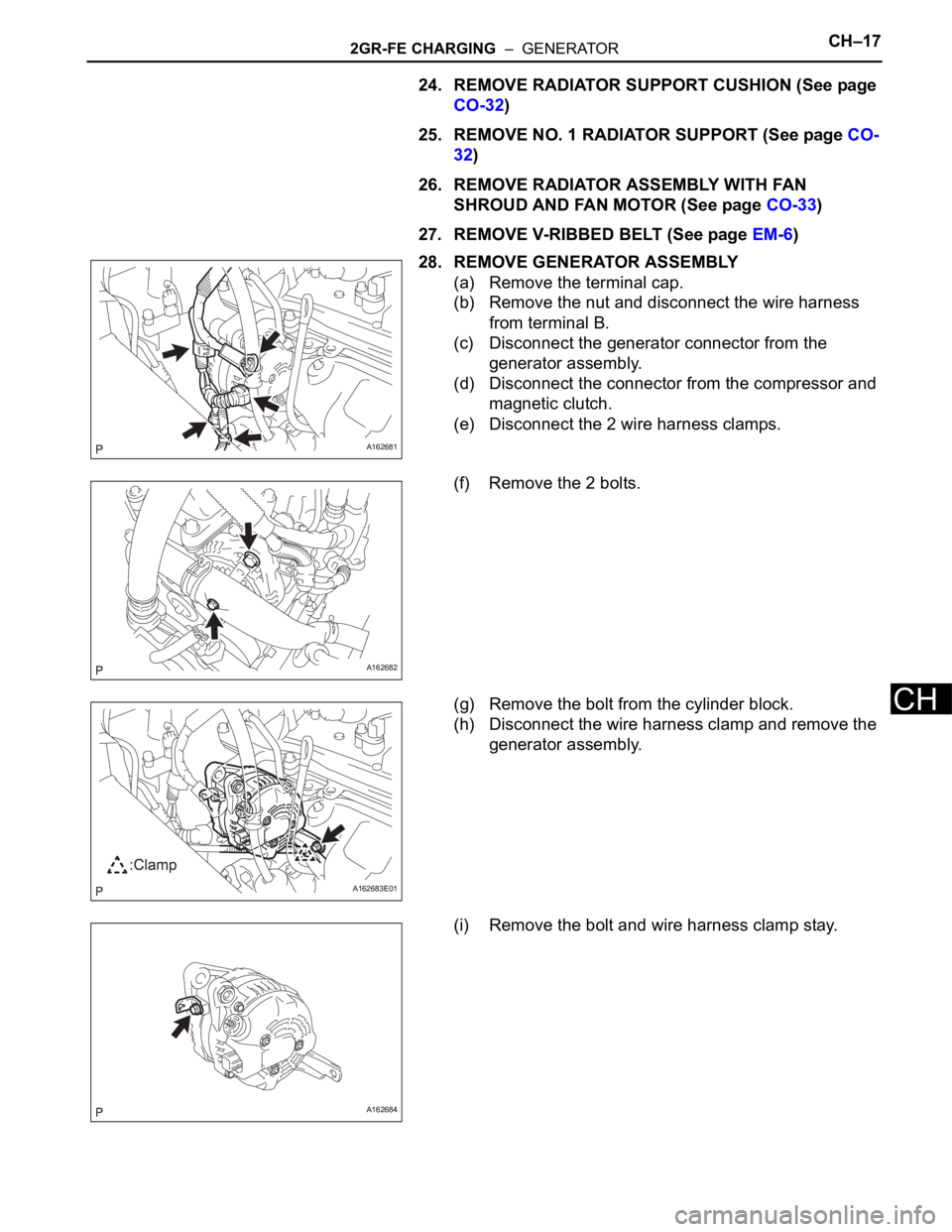
28. REMOVE GENERATOR ASSEMBLY
(a) Remove the terminal cap.
(b) Remove the nut and disconnect the wire harness
from terminal B.
(c) Disconnect the generator connector from the
generator assembly.
(d) Disconnect the connector from the compressor and
magnetic clutch.
(e) Disconnect the 2 wire harness clamps.
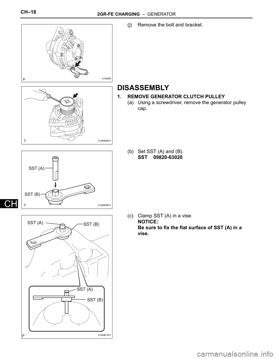
(f) Remove the 2 bolts.
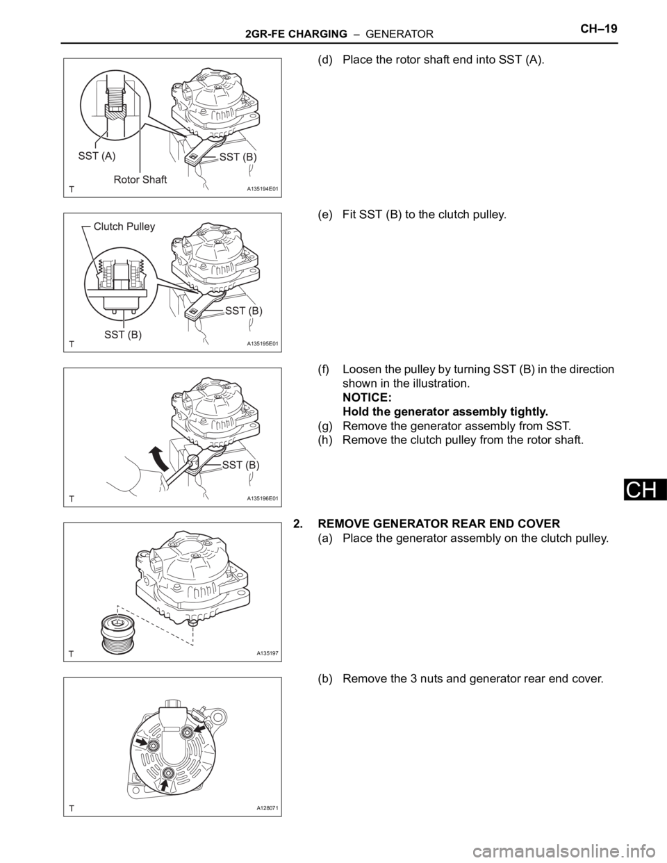
(g) Remove the bolt from the cylinder block.
(h) Disconnect the wire harness clamp and remove the
generator assembly.
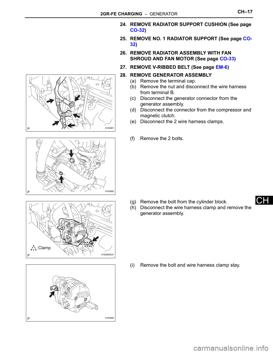
(i) Remove the bolt and wire harness clamp stay.
A162681
A162682
A162683E01
A162684
Page 1353 of 3000
CH–182GR-FE CHARGING – GENERATOR
CH
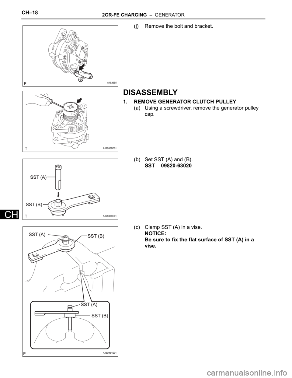
(j) Remove the bolt and bracket.
DISASSEMBLY
1. REMOVE GENERATOR CLUTCH PULLEY
(a) Using a screwdriver, remove the generator pulley
cap.
(b) Set SST (A) and (B).
SST 09820-63020
(c) Clamp SST (A) in a vise.
NOTICE:
Be sure to fix the flat surface of SST (A) in a
vise.
A162685
A128068E01
A128069E01
A160961E01
Page 1354 of 3000
2GR-FE CHARGING – GENERATORCH–19
CH
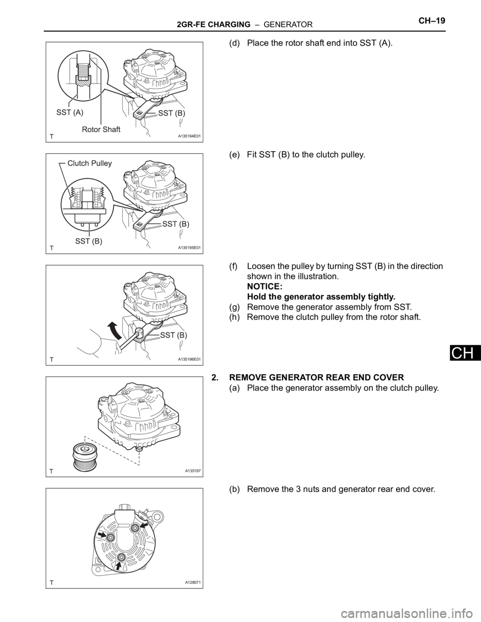
(d) Place the rotor shaft end into SST (A).
(e) Fit SST (B) to the clutch pulley.
(f) Loosen the pulley by turning SST (B) in the direction
shown in the illustration.
NOTICE:
Hold the generator assembly tightly.
(g) Remove the generator assembly from SST.
(h) Remove the clutch pulley from the rotor shaft.
2. REMOVE GENERATOR REAR END COVER
(a) Place the generator assembly on the clutch pulley.
(b) Remove the 3 nuts and generator rear end cover.
A135194E01
A135195E01
A135196E01
A135197
A128071
Page 1357 of 3000
2GR-FE CHARGING – GENERATORCH–17
CH
24. REMOVE RADIATOR SUPPORT CUSHION (See page
CO-32)
25. REMOVE NO. 1 RADIATOR SUPPORT (See page CO-
32)
26. REMOVE RADIATOR ASSEMBLY WITH FAN
SHROUD AND FAN MOTOR (See page CO-33)
27. REMOVE V-RIBBED BELT (See page EM-6)
28. REMOVE GENERATOR ASSEMBLY
(a) Remove the terminal cap.
(b) Remove the nut and disconnect the wire harness
from terminal B.
(c) Disconnect the generator connector from the
generator assembly.
(d) Disconnect the connector from the compressor and
magnetic clutch.
(e) Disconnect the 2 wire harness clamps.
(f) Remove the 2 bolts.
(g) Remove the bolt from the cylinder block.
(h) Disconnect the wire harness clamp and remove the
generator assembly.
(i) Remove the bolt and wire harness clamp stay.
A162681
A162682
A162683E01
A162684
Page 1358 of 3000
CH–182GR-FE CHARGING – GENERATOR
CH
(j) Remove the bolt and bracket.
DISASSEMBLY
1. REMOVE GENERATOR CLUTCH PULLEY
(a) Using a screwdriver, remove the generator pulley
cap.
(b) Set SST (A) and (B).
SST 09820-63020
(c) Clamp SST (A) in a vise.
NOTICE:
Be sure to fix the flat surface of SST (A) in a
vise.
A162685
A128068E01
A128069E01
A160961E01
Page 1359 of 3000
2GR-FE CHARGING – GENERATORCH–19
CH
(d) Place the rotor shaft end into SST (A).
(e) Fit SST (B) to the clutch pulley.
(f) Loosen the pulley by turning SST (B) in the direction
shown in the illustration.
NOTICE:
Hold the generator assembly tightly.
(g) Remove the generator assembly from SST.
(h) Remove the clutch pulley from the rotor shaft.
2. REMOVE GENERATOR REAR END COVER
(a) Place the generator assembly on the clutch pulley.
(b) Remove the 3 nuts and generator rear end cover.
A135194E01
A135195E01
A135196E01
A135197
A128071
Page 1361 of 3000
2GR-FE CHARGING – GENERATORCH–21
CH
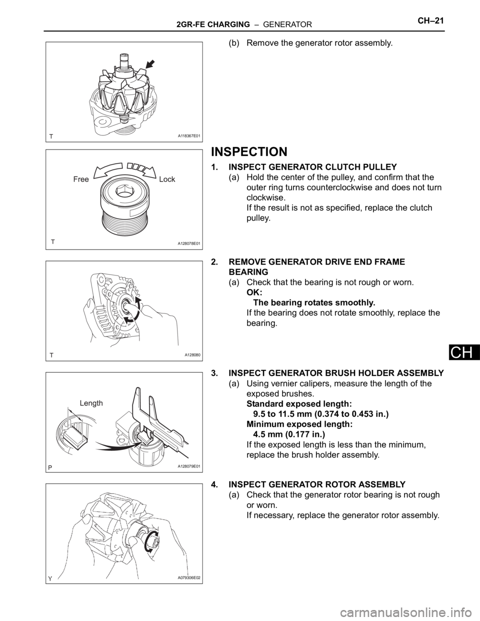
(b) Remove the generator rotor assembly.
INSPECTION
1. INSPECT GENERATOR CLUTCH PULLEY
(a) Hold the center of the pulley, and confirm that the
outer ring turns counterclockwise and does not turn
clockwise.
If the result is not as specified, replace the clutch
pulley.
2. REMOVE GENERATOR DRIVE END FRAME
BEARING
(a) Check that the bearing is not rough or worn.
OK:
The bearing rotates smoothly.
If the bearing does not rotate smoothly, replace the
bearing.
3. INSPECT GENERATOR BRUSH HOLDER ASSEMBLY
(a) Using vernier calipers, measure the length of the
exposed brushes.
Standard exposed length:
9.5 to 11.5 mm (0.374 to 0.453 in.)
Minimum exposed length:
4.5 mm (0.177 in.)
If the exposed length is less than the minimum,
replace the brush holder assembly.
4. INSPECT GENERATOR ROTOR ASSEMBLY
(a) Check that the generator rotor bearing is not rough
or worn.
If necessary, replace the generator rotor assembly.
A118367E01
A128078E01
A128080
A128079E01
A079306E02
Page 1364 of 3000
CH–242GR-FE CHARGING – GENERATOR
CH
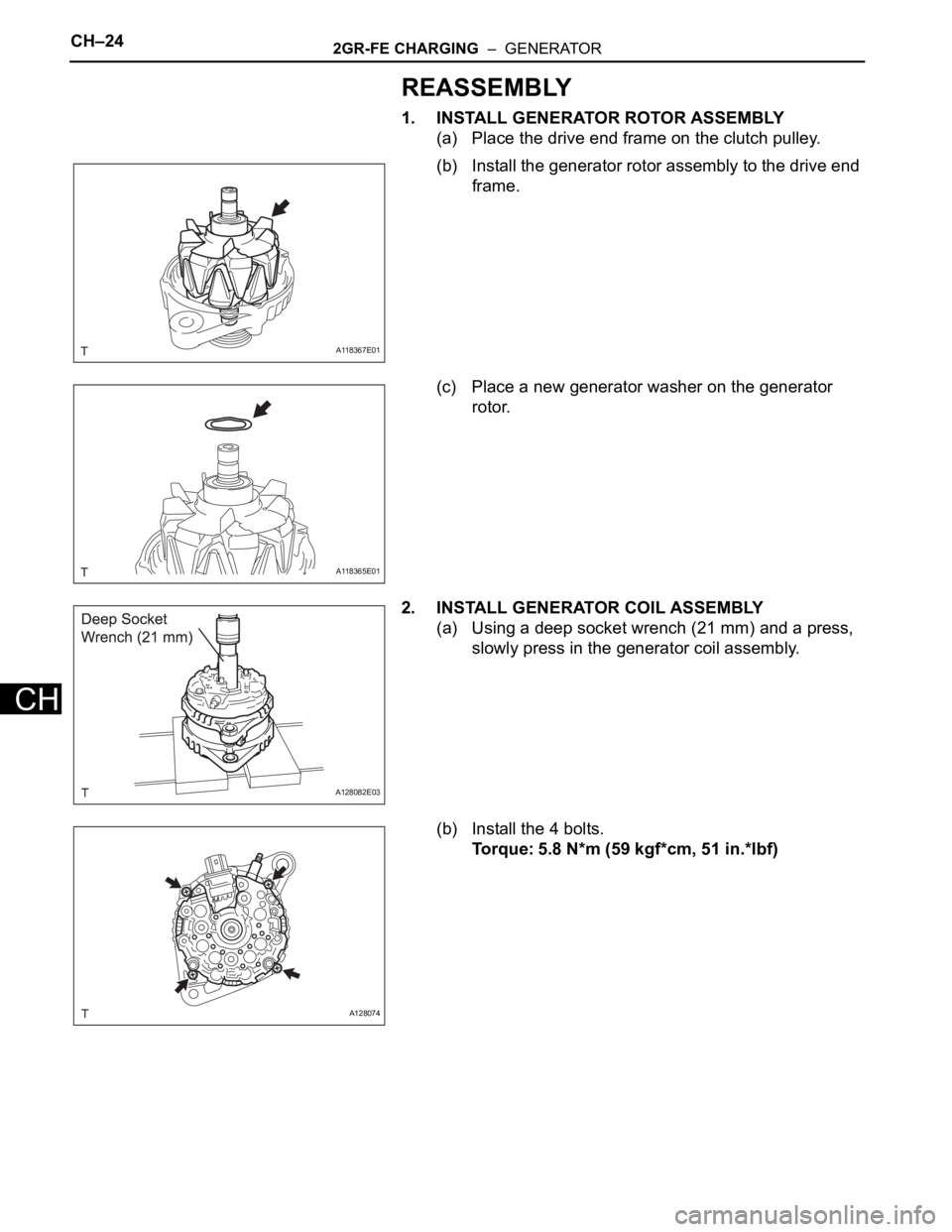
REASSEMBLY
1. INSTALL GENERATOR ROTOR ASSEMBLY
(a) Place the drive end frame on the clutch pulley.
(b) Install the generator rotor assembly to the drive end
frame.
(c) Place a new generator washer on the generator
rotor.
2. INSTALL GENERATOR COIL ASSEMBLY
(a) Using a deep socket wrench (21 mm) and a press,
slowly press in the generator coil assembly.
(b) Install the 4 bolts.
Torque: 5.8 N*m (59 kgf*cm, 51 in.*lbf)
A118367E01
A118365E01
A128082E03
A128074