Page 1114 of 3000
2GR-FE ENGINE MECHANICAL – ENGINE UNITEM–167
EM
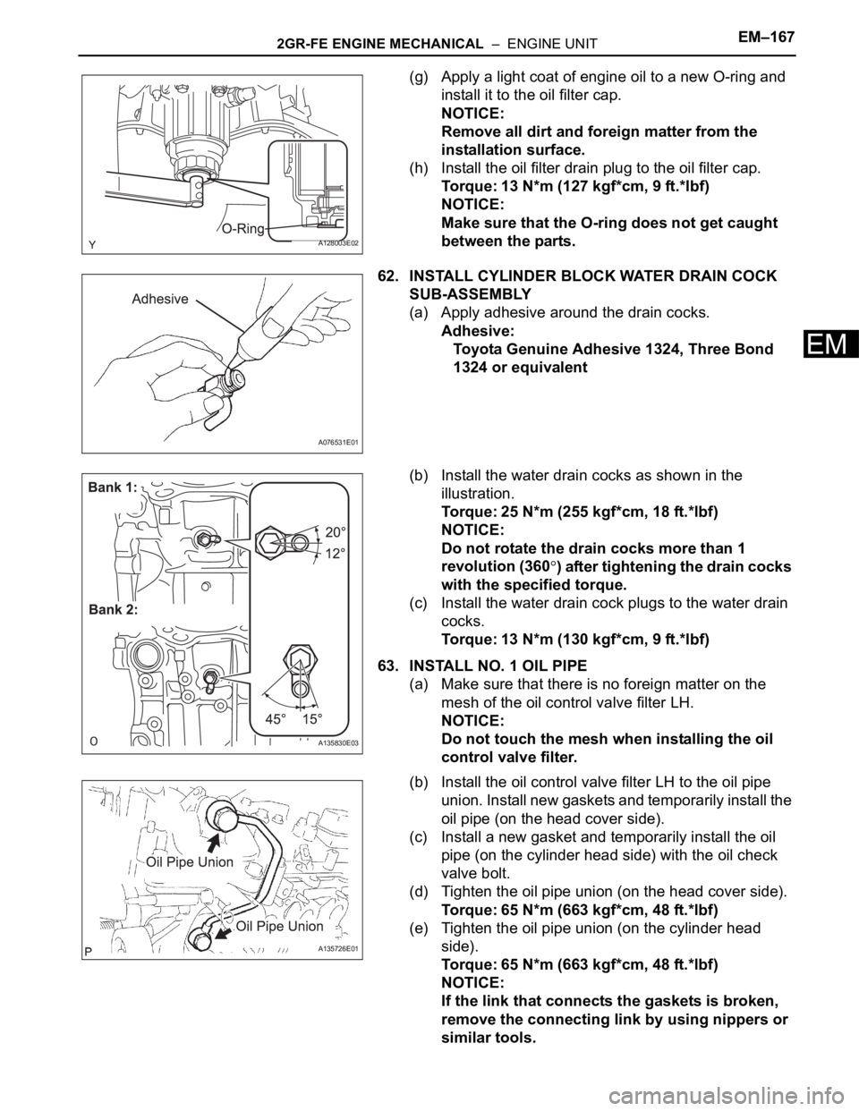
(g) Apply a light coat of engine oil to a new O-ring and
install it to the oil filter cap.
NOTICE:
Remove all dirt and foreign matter from the
installation surface.
(h) Install the oil filter drain plug to the oil filter cap.
Torque: 13 N*m (127 kgf*cm, 9 ft.*lbf)
NOTICE:
Make sure that the O-ring does not get caught
between the parts.
62. INSTALL CYLINDER BLOCK WATER DRAIN COCK
SUB-ASSEMBLY
(a) Apply adhesive around the drain cocks.
Adhesive:
Toyota Genuine Adhesive 1324, Three Bond
1324 or equivalent
(b) Install the water drain cocks as shown in the
illustration.
Torque: 25 N*m (255 kgf*cm, 18 ft.*lbf)
NOTICE:
Do not rotate the drain cocks more than 1
revolution (360
) after tightening the drain cocks
with the specified torque.
(c) Install the water drain cock plugs to the water drain
cocks.
Torque: 13 N*m (130 kgf*cm, 9 ft.*lbf)
63. INSTALL NO. 1 OIL PIPE
(a) Make sure that there is no foreign matter on the
mesh of the oil control valve filter LH.
NOTICE:
Do not touch the mesh when installing the oil
control valve filter.
(b) Install the oil control valve filter LH to the oil pipe
union. Install new gaskets and temporarily install the
oil pipe (on the head cover side).
(c) Install a new gasket and temporarily install the oil
pipe (on the cylinder head side) with the oil check
valve bolt.
(d) Tighten the oil pipe union (on the head cover side).
Torque: 65 N*m (663 kgf*cm, 48 ft.*lbf)
(e) Tighten the oil pipe union (on the cylinder head
side).
Torque: 65 N*m (663 kgf*cm, 48 ft.*lbf)
NOTICE:
If the link that connects the gaskets is broken,
remove the connecting link by using nippers or
similar tools.
A128003E02
A076531E01
A135830E03
A135726E01
Page 1115 of 3000
EM–1682GR-FE ENGINE MECHANICAL – ENGINE UNIT
EM
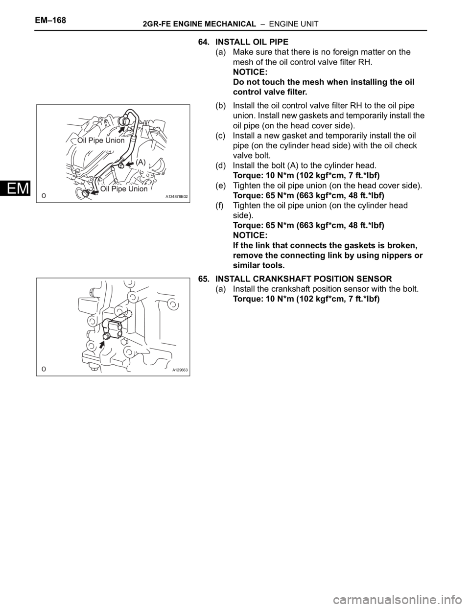
64. INSTALL OIL PIPE
(a) Make sure that there is no foreign matter on the
mesh of the oil control valve filter RH.
NOTICE:
Do not touch the mesh when installing the oil
control valve filter.
(b) Install the oil control valve filter RH to the oil pipe
union. Install new gaskets and temporarily install the
oil pipe (on the head cover side).
(c) Install a new gasket and temporarily install the oil
pipe (on the cylinder head side) with the oil check
valve bolt.
(d) Install the bolt (A) to the cylinder head.
Torque: 10 N*m (102 kgf*cm, 7 ft.*lbf)
(e) Tighten the oil pipe union (on the head cover side).
Torque: 65 N*m (663 kgf*cm, 48 ft.*lbf)
(f) Tighten the oil pipe union (on the cylinder head
side).
Torque: 65 N*m (663 kgf*cm, 48 ft.*lbf)
NOTICE:
If the link that connects the gaskets is broken,
remove the connecting link by using nippers or
similar tools.
65. INSTALL CRANKSHAFT POSITION SENSOR
(a) Install the crankshaft position sensor with the bolt.
Torque: 10 N*m (102 kgf*cm, 7 ft.*lbf)
A134878E02
A129663
Page 1152 of 3000
FU–342GR-FE FUEL – FUEL PUMP
FU
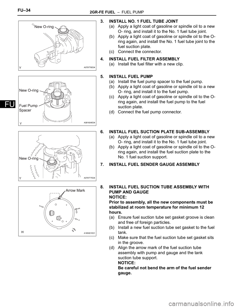
3. INSTALL NO. 1 FUEL TUBE JOINT
(a) Apply a light coat of gasoline or spindle oil to a new
O- ring, and install it to the No. 1 fuel tube joint.
(b) Apply a light coat of gasoline or spindle oil to the O-
ring again, and install the No. 1 fuel tube joint to the
fuel suction plate.
(c) Connect the connector.
4. INSTALL FUEL FILTER ASSEMBLY
(a) Install the fuel filter with a new clip.
5. INSTALL FUEL PUMP
(a) Install the fuel pump spacer to the fuel pump.
(b) Apply a light coat of gasoline or spindle oil to a new
O- ring, and install it to the fuel pump.
(c) Apply a light coat of gasoline or spindle oil to the O-
ring again, and install the fuel pump to the fuel
suction plate.
(d) Connect the fuel pump connector.
6. INSTALL FUEL SUCTION PLATE SUB-ASSEMBLY
(a) Apply a light coat of gasoline or spindle oil to a new
O- ring, and install it to the No. 1 fuel tube joint.
(b) Apply a light coat of gasoline or spindle oil to the O-
ring again, and install the fuel suction plate to the
No. 1 fuel suction support.
7. INSTALL FUEL SENDER GAUGE ASSEMBLY
8. INSTALL FUEL SUCTION TUBE ASSEMBLY WITH
PUMP AND GAUGE
NOTICE:
Prior to assembly, all the new components must be
stabilized at room temperature for minimum 12
hours.
(a) Ensure fuel suction tube set gasket groove is clean
and free of foreign particles.
(b) Install a new fuel suction tube set gasket to the fuel
tank.
(c) Make sure that the fuel suction tube set gasket sits
in the groove.
(d) Align the arrow mark of the fuel suction tube
assembly with pump and gauge and the tank
suction tube support.
NOTICE:
Be careful not bend the arm of the fuel sender
gauge.
A079776E04
A081604E04
A079777E04
A165001E01
Page 1157 of 3000
FU–342GR-FE FUEL – FUEL PUMP
FU
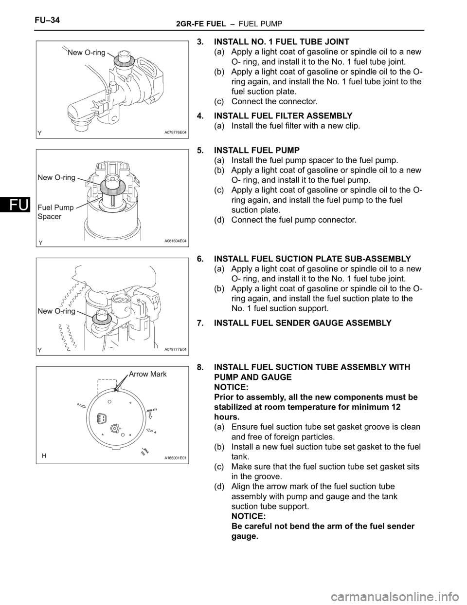
3. INSTALL NO. 1 FUEL TUBE JOINT
(a) Apply a light coat of gasoline or spindle oil to a new
O- ring, and install it to the No. 1 fuel tube joint.
(b) Apply a light coat of gasoline or spindle oil to the O-
ring again, and install the No. 1 fuel tube joint to the
fuel suction plate.
(c) Connect the connector.
4. INSTALL FUEL FILTER ASSEMBLY
(a) Install the fuel filter with a new clip.
5. INSTALL FUEL PUMP
(a) Install the fuel pump spacer to the fuel pump.
(b) Apply a light coat of gasoline or spindle oil to a new
O- ring, and install it to the fuel pump.
(c) Apply a light coat of gasoline or spindle oil to the O-
ring again, and install the fuel pump to the fuel
suction plate.
(d) Connect the fuel pump connector.
6. INSTALL FUEL SUCTION PLATE SUB-ASSEMBLY
(a) Apply a light coat of gasoline or spindle oil to a new
O- ring, and install it to the No. 1 fuel tube joint.
(b) Apply a light coat of gasoline or spindle oil to the O-
ring again, and install the fuel suction plate to the
No. 1 fuel suction support.
7. INSTALL FUEL SENDER GAUGE ASSEMBLY
8. INSTALL FUEL SUCTION TUBE ASSEMBLY WITH
PUMP AND GAUGE
NOTICE:
Prior to assembly, all the new components must be
stabilized at room temperature for minimum 12
hours.
(a) Ensure fuel suction tube set gasket groove is clean
and free of foreign particles.
(b) Install a new fuel suction tube set gasket to the fuel
tank.
(c) Make sure that the fuel suction tube set gasket sits
in the groove.
(d) Align the arrow mark of the fuel suction tube
assembly with pump and gauge and the tank
suction tube support.
NOTICE:
Be careful not bend the arm of the fuel sender
gauge.
A079776E04
A081604E04
A079777E04
A165001E01
Page 1299 of 3000
2GR-FE LUBRICATION – LUBRICATION SYSTEMLU–1
LU
LUBRICATION SYSTEM
ON-VEHICLE INSPECTION
1. CHECK ENGINE OIL LEVEL
(a) Warm up the engine, stop it and wait 5 minutes. The
oil level should be between the dipstick's low level
mark and full level mark.
If the engine oil level is low, check for leakage and
add oil up to the full level mark.
NOTICE:
Do not add engine oil above the full level mark.
2. CHECK ENGINE OIL
(a) Check the engine oil for deterioration, water
contamination, discoloring or thinning.
If the oil is bad, replace the engine oil and engine oil
filter.
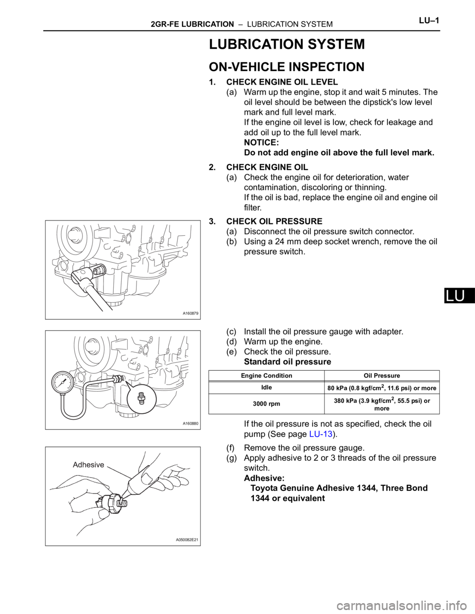
3. CHECK OIL PRESSURE
(a) Disconnect the oil pressure switch connector.
(b) Using a 24 mm deep socket wrench, remove the oil
pressure switch.
(c) Install the oil pressure gauge with adapter.
(d) Warm up the engine.
(e) Check the oil pressure.
Standard oil pressure
If the oil pressure is not as specified, check the oil
pump (See page LU-13).
(f) Remove the oil pressure gauge.
(g) Apply adhesive to 2 or 3 threads of the oil pressure
switch.
Adhesive:
Toyota Genuine Adhesive 1344, Three Bond
1344 or equivalent
A160879
A160880
Engine Condition Oil Pressure
Idle
80 kPa (0.8 kgf/cm
2, 11.6 psi) or more
3000 rpm380 kPa (3.9 kgf/cm
2, 55.5 psi) or
more
A050082E21
Page 1301 of 3000
2GR-FE LUBRICATION – OIL AND OIL FILTERLU–3
LU
ENGINE
2GR-FE LUBRICATION
OIL AND OIL FILTER
COMPONENTS
A161392E01
Page 1302 of 3000
LU–42GR-FE LUBRICATION – OIL AND OIL FILTER
LU
REPLACEMENT
CAUTION:
• Prolonged and repeated contact with engine oil will
result in the removal of natural oils from the skin,
leading to dryness, irritation and dermatitis. In
addition, used engine oil contains potentially harmful
contaminants which may cause skin cancer.
• Precautions should be taken when replacing engine
oil to minimize the risk of your skin making contact
with used engine oil. Protective clothing and gloves
that cannot be penetrated by oil should be worn. The
skin should be washed with soap and water, or
waterless hand cleaner, to remove any used engine oil
thoroughly. Do not use gasoline, thinners, or solvents.
• In order to preserve the environment, used oil and
used oil filters must be disposed of at designated
disposal sites.
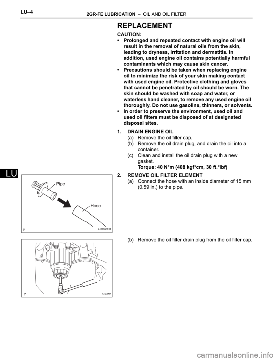
1. DRAIN ENGINE OIL
(a) Remove the oil filler cap.
(b) Remove the oil drain plug, and drain the oil into a
container.
(c) Clean and install the oil drain plug with a new
gasket.
Torque: 40 N*m (408 kgf*cm, 30 ft.*lbf)
2. REMOVE OIL FILTER ELEMENT
(a) Connect the hose with an inside diameter of 15 mm
(0.59 in.) to the pipe.
(b) Remove the oil filter drain plug from the oil filter cap.
A127996E01
A127997
Page 1303 of 3000
2GR-FE LUBRICATION – OIL AND OIL FILTERLU–5
LU
(c) Insert the pipe with the hose into the oil filter cap.
NOTICE:
Be sure to insert the pipe with the O-ring
installed on the oil filter cap side.
HINT:
Place the hose end into a container before draining
oil from the hose.
(d) Make sure that oil is completely drained, and
remove the pipe and O-ring.
HINT:
Be sure to turn the pipe in the direction of the arrow
to remove it.
(e) Using SST, remove the oil filter cap.
SST 09228-06501
(f) Remove the oil filter element and O-ring from the oil
filter cap.
NOTICE:
Do not use any tools to remove the O-ring in
order to prevent the cap from being damaged.
Be sure to remove it by hand.
A160741E01
A127999
A128000E01
A128001E01