Page 600 of 3000

2GR-FE ENGINE CONTROL SYSTEM – SFI SYSTEMES–307
ES
NG
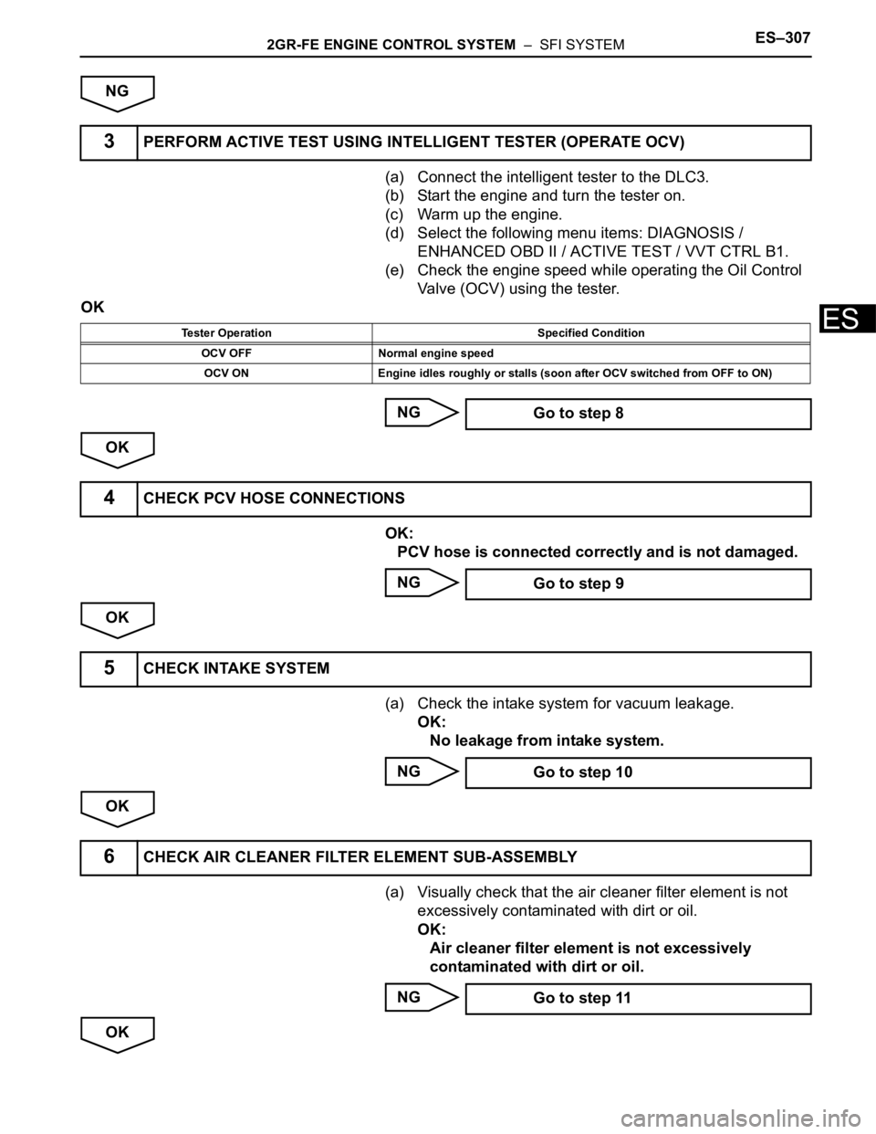
(a) Connect the intelligent tester to the DLC3.
(b) Start the engine and turn the tester on.
(c) Warm up the engine.
(d) Select the following menu items: DIAGNOSIS /
ENHANCED OBD II / ACTIVE TEST / VVT CTRL B1.
(e) Check the engine speed while operating the Oil Control
Valve (OCV) using the tester.
OK
NG
OK
OK:
PCV hose is connected correctly and is not damaged.
NG
OK
(a) Check the intake system for vacuum leakage.
OK:
No leakage from intake system.
NG
OK
(a) Visually check that the air cleaner filter element is not
excessively contaminated with dirt or oil.
OK:
Air cleaner filter element is not excessively
contaminated with dirt or oil.
NG
OK
3PERFORM ACTIVE TEST USING INTELLIGENT TESTER (OPERATE OCV)
Tester Operation Specified Condition
OCV OFF Normal engine speed
OCV ON Engine idles roughly or stalls (soon after OCV switched from OFF to ON)
Go to step 8
4CHECK PCV HOSE CONNECTIONS
Go to step 9
5CHECK INTAKE SYSTEM
Go to step 10
6CHECK AIR CLEANER FILTER ELEMENT SUB-ASSEMBLY
Go to step 11
Page 606 of 3000

2GR-FE ENGINE CONTROL SYSTEM – SFI SYSTEMES–313
ES
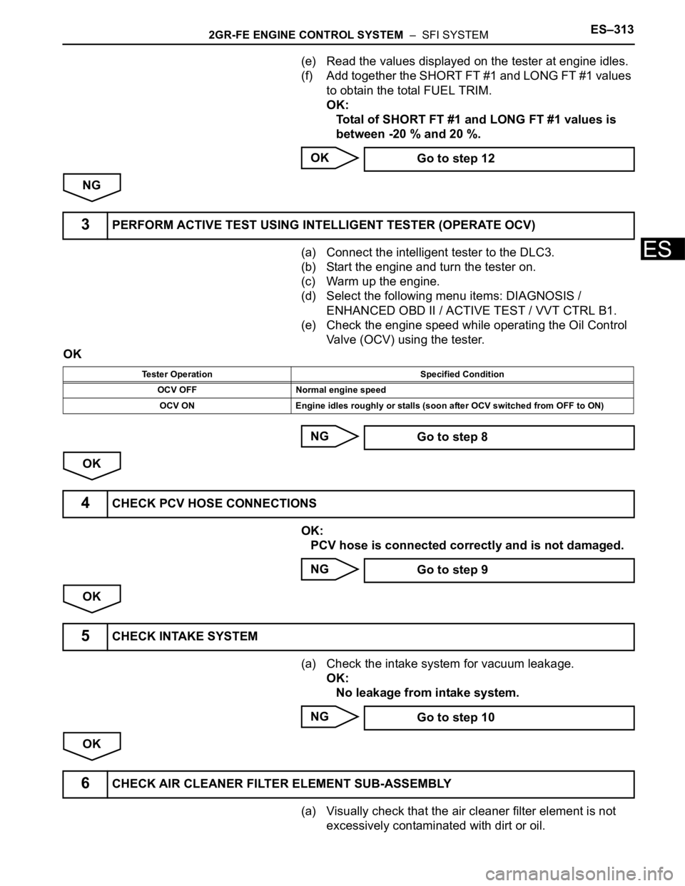
(e) Read the values displayed on the tester at engine idles.
(f) Add together the SHORT FT #1 and LONG FT #1 values
to obtain the total FUEL TRIM.
OK:
Total of SHORT FT #1 and LONG FT #1 values is
between -20 % and 20 %.
OK
NG
(a) Connect the intelligent tester to the DLC3.
(b) Start the engine and turn the tester on.
(c) Warm up the engine.
(d) Select the following menu items: DIAGNOSIS /
ENHANCED OBD II / ACTIVE TEST / VVT CTRL B1.
(e) Check the engine speed while operating the Oil Control
Valve (OCV) using the tester.
OK
NG
OK
OK:
PCV hose is connected correctly and is not damaged.
NG
OK
(a) Check the intake system for vacuum leakage.
OK:
No leakage from intake system.
NG
OK
(a) Visually check that the air cleaner filter element is not
excessively contaminated with dirt or oil. Go to step 12
3PERFORM ACTIVE TEST USING INTELLIGENT TESTER (OPERATE OCV)
Tester Operation Specified Condition
OCV OFF Normal engine speed
OCV ON Engine idles roughly or stalls (soon after OCV switched from OFF to ON)
Go to step 8
4CHECK PCV HOSE CONNECTIONS
Go to step 9
5CHECK INTAKE SYSTEM
Go to step 10
6CHECK AIR CLEANER FILTER ELEMENT SUB-ASSEMBLY
Page 607 of 3000
ES–3142GR-FE ENGINE CONTROL SYSTEM – SFI SYSTEM
ES
OK:
Air cleaner filter element is not excessively
contaminated with dirt or oil.
NG
OK
NEXT
NEXT
NEXT
NEXT
NEXT
(a) Check for deposits around the throttle valve and throttle
valve condition.
OK:
No deposits around throttle valve and throttle valve
moves smoothly.
NG
OK
NEXT Go to step 11
7REPLACE MASS AIR FLOW METER
Go to step 15
8CHECK AND REPAIR VVT SENSOR
Go to step 15
9REPAIR OR REPLACE PCV HOSE
Go to step 15
10REPAIR OR REPLACE INTAKE SYSTEM
Go to step 15
11REPLACE AIR CLEANER FILTER ELEMENT SUB-ASSEMBLY
Go to step 15
12CHECK THROTTLE VALVE
Go to step 14
13REPLACE ECM
Go to step 15
Page 777 of 3000
2GR-FE ENGINE CONTROL SYSTEM – SFI SYSTEMES–15
ES
BASIC INSPECTION
When a malfunction is not confirmed by the DTC check,
troubleshooting should be carried out in all circuits
considered to be possible causes of the problem. In many
cases, by carrying out the basic engine check shown in the
following flowchart, the location of the problem can be found
quickly and efficiently. Therefore, using this check is essential
when engine troubleshooting.
NOTICE:
Carry out this check with the engine stopped and ignition
switch off.
Result
NG
OK
NG
OK
NG
OK
(a) Visually check that the air filter is not excessively
contaminated with dirt or oil.
NG
OK
(a) Check the idling speed (See page EM-2).
1CHECK BATTERY VOLTAGE
Result Proceed to
11 V or more OK
Below 11 V NG
CHARGE OR REPLACE BATTERY
2CHECK WHETHER ENGINE CRANKS
PROCEED TO PROBLEM SYMPTOMS
TA B L E
3CHECK WHETHER ENGINE STARTS
GO TO STEP 6
4CHECK AIR FILTER
REPLACE AIR FILTER
5CHECK IDLING SPEED
Page 882 of 3000
2GR-FE ENGINE MECHANICAL – ENGINE UNITEM–77
EM
6. REMOVE CAMSHAFT TIMING OIL CONTROL VALVE
ASSEMBLY
(a) Remove the 4 bolts and 4 camshaft oil control
valves.
7. REMOVE CRANKSHAFT POSITION SENSOR
(a) Remove the bolt and crankshaft position sensor.
8. REMOVE NO. 1 OIL PIPE
(a) Remove the 2 oil pipe unions, gaskets and oil pipe.
(b) Remove the oil control valve filter LH and gaskets.
9. REMOVE OIL PIPE
(a) Remove the bolt.
(b) Remove the 2 oil pipe unions and oil pipe.
(c) Remove the oil control valve filter RH and gaskets.
A129662E06
A129663
A135726E01
A134878E01
Page 883 of 3000
EM–782GR-FE ENGINE MECHANICAL – ENGINE UNIT
EM
10. REMOVE CYLINDER BLOCK WATER DRAIN COCK
SUB-ASSEMBLY
(a) Remove the cylinder block water drain cocks from
the cylinder block.
(b) Remove the cylinder block water drain cock plugs
from the water drain cocks.
11. REMOVE OIL FILTER ELEMENT
(a) Remove the drain plug.
NOTICE:
Do not remove the O-ring from the oil filter cap.
(b) Connect the hose to the pipe.
(c) Insert the pipe with the hose into the oil filter cap.
(d) Make sure that the oil is completely drained and
remove the pipe and O-ring.
A135829E03
A129666
A129667E01
Page 884 of 3000
2GR-FE ENGINE MECHANICAL – ENGINE UNITEM–79
EM
(e) Using SST, remove the oil filter cap sub-assembly.
SST 09228-06501
(f) Remove the oil filter element and O-ring from the oil
filter cap sub-assembly.
NOTICE:
Do not use any tools when removing the O-ring
to prevent the O-ring groove from being
damaged.
12. REMOVE CRANKSHAFT PULLEY
(a) Using SST, loosen the crankshaft pulley bolt.
SST 09213-70011 (09213-70020), 09330-00021
(b) Using SST, remove the crankshaft pulley bolt and
crankshaft pulley.
SST 09950-50013 (09951-05010, 09952-05010,
09953-05020, 09954-05021)
A129668E01
A106167E01
A120690E02
A120691E02
Page 931 of 3000

2GR-FE ENGINE MECHANICAL – ENGINEEM–1
EM
ENGINE
ON-VEHICLE INSPECTION
1. INSPECT ENGINE COOLANT
(a) Inspect the engine coolant (See page CO-1).
2. INSPECT ENGINE OIL
(a) Inspect the engine oil (See page LU-1).
3. INSPECT BATTERY
(a) Inspect the battery (See page CH-5).
4. INSPECT AIR CLEANER FILTER ELEMENT SUB-
ASSEMBLY
(a) Remove the air cleaner filter element sub-assembly.
(b) Visually check that there is no dirt, blockage, and/or
damage to the air cleaner filter element.
HINT:
• If there is any dirt or a blockage in the air cleaner
filter element, clean it with compressed air.
• If any dirt or a blockage remains even after
cleaning the air cleaner filter element with
compressed air, replace it.
5. INSPECT SPARK PLUG
(a) Inspect the spark plugs (See page IG-5).
6. INSPECT VALVE LASH ADJUSTER NOISE
(a) Rev up the engine several times. Check that the
engine does not emit unusual noises.
If unusual noises occur, warm up the engine and
idle it for over 30 minutes. Then repeat this
procedure.
HINT:
If any defects or problems are found during the
inspection above, perform lash adjuster inspection
(See page EM-100).
7. INSPECT IGNITION TIMING
(a) Warm up the engine.
(b) When using the intelligent tester:
Check the ignition timing.
(1) Connect the intelligent tester to the DLC3.
(2) Enter DATA LIST mode with the intelligent
tester.
Ignition timing:
8 to 12
BTDC at idle
HINT:
Refer to the intelligent tester operator's manual
for help when selecting the DATA LIST.
C110200E02