Page 934 of 3000
EM–42GR-FE ENGINE MECHANICAL – ENGINE
EM
(h) Install the 6 ignition coils.
Torque: 10 N*m (102 kgf*cm, 7 ft.*lbf)
(i) Install the intake air surge tank (See page ES-522).
10. INSPECT CO/HC
(a) Start the engine.
(b) Run the engine at 2500 rpm for approximately 180
seconds.
(c) Insert the CO/HC meter testing probe at least 40 cm
(1.3 ft.) into the tailpipe during idling.
(d) Check CO/HC concentration at idle and/or 2500
rpm.
HINT:
Check regulations and restrictions in your area
when performing 2 mode CO/HC concentration
testing (engine check at both idle speed and at 2500
rpm).
If the CO/HC concentration does not comply with
regulations, perform troubleshooting in the order
given below.
(1) Check air fuel ratio sensor and heated oxygen
sensor operation.
(2) See the table below for possible causes, and
then inspect and repair.
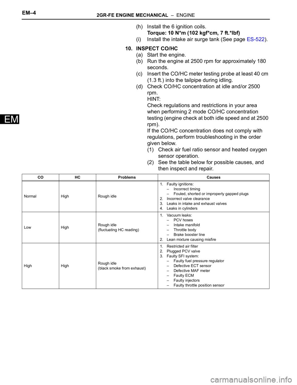
CO HC Problems Causes
Normal High Rough idle1. Faulty ignitions:
– Incorrect timing
– Fouled, shorted or improperly gapped plugs
2. Incorrect valve clearance
3. Leaks in intake and exhaust valves
4. Leaks in cylinders
Low HighRough idle
(fluctuating HC reading)1. Vacuum leaks:
– PCV hoses
– Intake manifold
– Throttle body
– Brake booster line
2. Lean mixture causing misfire
High HighRough idle
(black smoke from exhaust)1. Restricted air filter
2. Plugged PCV valve
3. Faulty SFI system:
– Faulty fuel pressure regulator
– Defective ECT sensor
– Defective MAF meter
–Faulty ECM
– Faulty injectors
– Faulty throttle position sensor
Page 975 of 3000
EM–1662GR-FE ENGINE MECHANICAL – ENGINE UNIT
EM
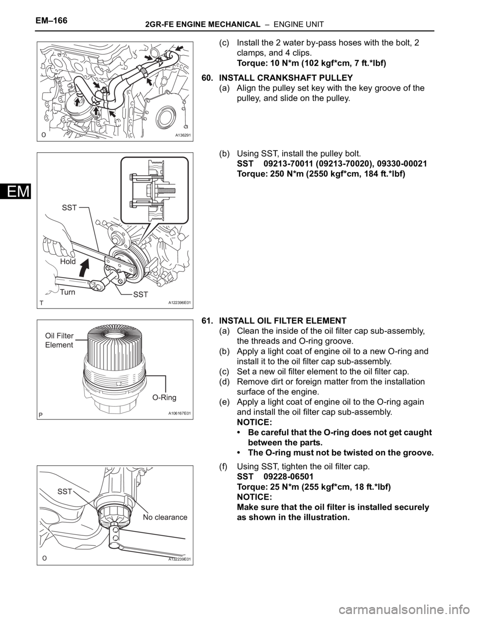
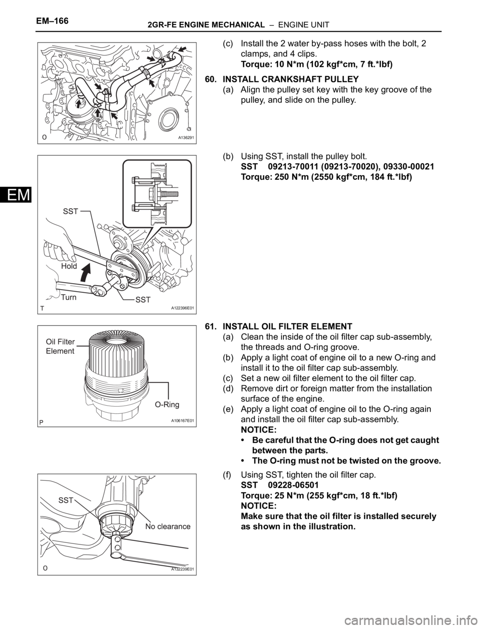
(c) Install the 2 water by-pass hoses with the bolt, 2
clamps, and 4 clips.
Torque: 10 N*m (102 kgf*cm, 7 ft.*lbf)
60. INSTALL CRANKSHAFT PULLEY
(a) Align the pulley set key with the key groove of the
pulley, and slide on the pulley.
(b) Using SST, install the pulley bolt.
SST 09213-70011 (09213-70020), 09330-00021
Torque: 250 N*m (2550 kgf*cm, 184 ft.*lbf)
61. INSTALL OIL FILTER ELEMENT
(a) Clean the inside of the oil filter cap sub-assembly,
the threads and O-ring groove.
(b) Apply a light coat of engine oil to a new O-ring and
install it to the oil filter cap sub-assembly.
(c) Set a new oil filter element to the oil filter cap.
(d) Remove dirt or foreign matter from the installation
surface of the engine.
(e) Apply a light coat of engine oil to the O-ring again
and install the oil filter cap sub-assembly.
NOTICE:
• Be careful that the O-ring does not get caught
between the parts.
• The O-ring must not be twisted on the groove.
(f) Using SST, tighten the oil filter cap.
SST 09228-06501
Torque: 25 N*m (255 kgf*cm, 18 ft.*lbf)
NOTICE:
Make sure that the oil filter is installed securely
as shown in the illustration.
A136291
A122396E01
A106167E01
A132239E01
Page 976 of 3000
2GR-FE ENGINE MECHANICAL – ENGINE UNITEM–167
EM
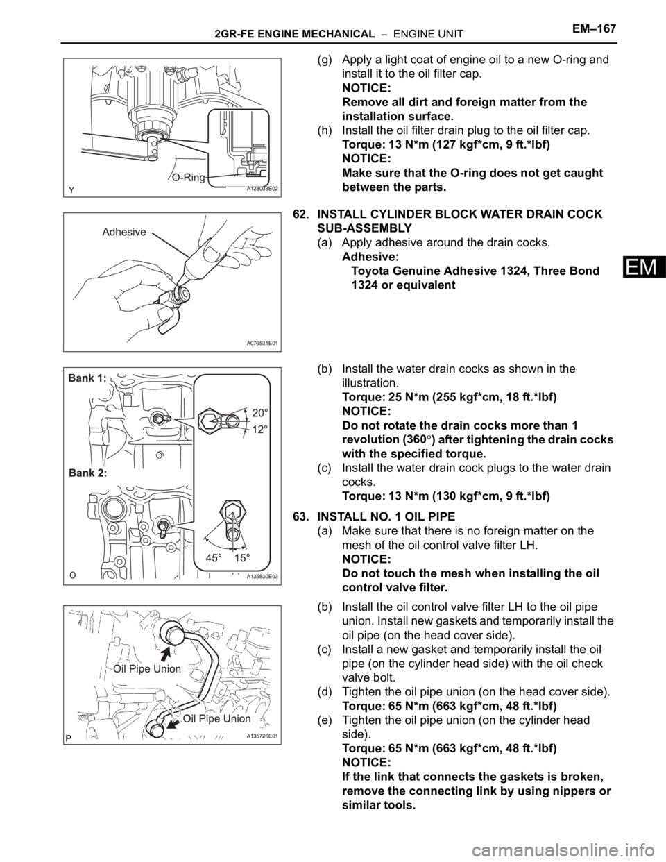
(g) Apply a light coat of engine oil to a new O-ring and
install it to the oil filter cap.
NOTICE:
Remove all dirt and foreign matter from the
installation surface.
(h) Install the oil filter drain plug to the oil filter cap.
Torque: 13 N*m (127 kgf*cm, 9 ft.*lbf)
NOTICE:
Make sure that the O-ring does not get caught
between the parts.
62. INSTALL CYLINDER BLOCK WATER DRAIN COCK
SUB-ASSEMBLY
(a) Apply adhesive around the drain cocks.
Adhesive:
Toyota Genuine Adhesive 1324, Three Bond
1324 or equivalent
(b) Install the water drain cocks as shown in the
illustration.
Torque: 25 N*m (255 kgf*cm, 18 ft.*lbf)
NOTICE:
Do not rotate the drain cocks more than 1
revolution (360
) after tightening the drain cocks
with the specified torque.
(c) Install the water drain cock plugs to the water drain
cocks.
Torque: 13 N*m (130 kgf*cm, 9 ft.*lbf)
63. INSTALL NO. 1 OIL PIPE
(a) Make sure that there is no foreign matter on the
mesh of the oil control valve filter LH.
NOTICE:
Do not touch the mesh when installing the oil
control valve filter.
(b) Install the oil control valve filter LH to the oil pipe
union. Install new gaskets and temporarily install the
oil pipe (on the head cover side).
(c) Install a new gasket and temporarily install the oil
pipe (on the cylinder head side) with the oil check
valve bolt.
(d) Tighten the oil pipe union (on the head cover side).
Torque: 65 N*m (663 kgf*cm, 48 ft.*lbf)
(e) Tighten the oil pipe union (on the cylinder head
side).
Torque: 65 N*m (663 kgf*cm, 48 ft.*lbf)
NOTICE:
If the link that connects the gaskets is broken,
remove the connecting link by using nippers or
similar tools.
A128003E02
A076531E01
A135830E03
A135726E01
Page 977 of 3000
EM–1682GR-FE ENGINE MECHANICAL – ENGINE UNIT
EM
64. INSTALL OIL PIPE
(a) Make sure that there is no foreign matter on the
mesh of the oil control valve filter RH.
NOTICE:
Do not touch the mesh when installing the oil
control valve filter.
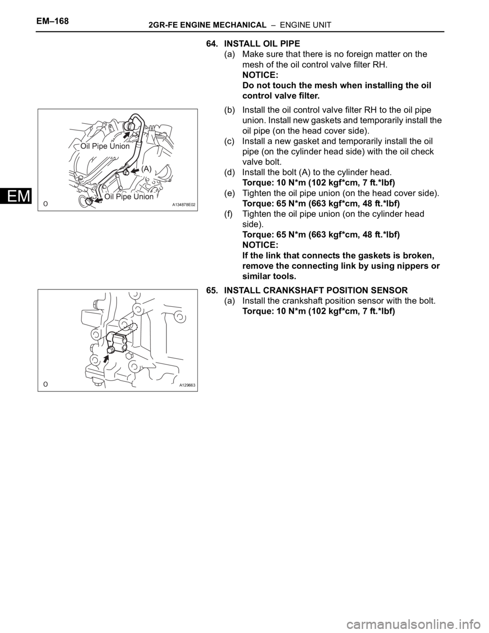
(b) Install the oil control valve filter RH to the oil pipe
union. Install new gaskets and temporarily install the
oil pipe (on the head cover side).
(c) Install a new gasket and temporarily install the oil
pipe (on the cylinder head side) with the oil check
valve bolt.
(d) Install the bolt (A) to the cylinder head.
Torque: 10 N*m (102 kgf*cm, 7 ft.*lbf)
(e) Tighten the oil pipe union (on the head cover side).
Torque: 65 N*m (663 kgf*cm, 48 ft.*lbf)
(f) Tighten the oil pipe union (on the cylinder head
side).
Torque: 65 N*m (663 kgf*cm, 48 ft.*lbf)
NOTICE:
If the link that connects the gaskets is broken,
remove the connecting link by using nippers or
similar tools.
65. INSTALL CRANKSHAFT POSITION SENSOR
(a) Install the crankshaft position sensor with the bolt.
Torque: 10 N*m (102 kgf*cm, 7 ft.*lbf)
A134878E02
A129663
Page 1024 of 3000
2GR-FE ENGINE MECHANICAL – ENGINE UNITEM–77
EM
6. REMOVE CAMSHAFT TIMING OIL CONTROL VALVE
ASSEMBLY
(a) Remove the 4 bolts and 4 camshaft oil control
valves.
7. REMOVE CRANKSHAFT POSITION SENSOR
(a) Remove the bolt and crankshaft position sensor.
8. REMOVE NO. 1 OIL PIPE
(a) Remove the 2 oil pipe unions, gaskets and oil pipe.
(b) Remove the oil control valve filter LH and gaskets.
9. REMOVE OIL PIPE
(a) Remove the bolt.
(b) Remove the 2 oil pipe unions and oil pipe.
(c) Remove the oil control valve filter RH and gaskets.
A129662E06
A129663
A135726E01
A134878E01
Page 1025 of 3000
EM–782GR-FE ENGINE MECHANICAL – ENGINE UNIT
EM
10. REMOVE CYLINDER BLOCK WATER DRAIN COCK
SUB-ASSEMBLY
(a) Remove the cylinder block water drain cocks from
the cylinder block.
(b) Remove the cylinder block water drain cock plugs
from the water drain cocks.
11. REMOVE OIL FILTER ELEMENT
(a) Remove the drain plug.
NOTICE:
Do not remove the O-ring from the oil filter cap.
(b) Connect the hose to the pipe.
(c) Insert the pipe with the hose into the oil filter cap.
(d) Make sure that the oil is completely drained and
remove the pipe and O-ring.
A135829E03
A129666
A129667E01
Page 1026 of 3000
2GR-FE ENGINE MECHANICAL – ENGINE UNITEM–79
EM
(e) Using SST, remove the oil filter cap sub-assembly.
SST 09228-06501
(f) Remove the oil filter element and O-ring from the oil
filter cap sub-assembly.
NOTICE:
Do not use any tools when removing the O-ring
to prevent the O-ring groove from being
damaged.
12. REMOVE CRANKSHAFT PULLEY
(a) Using SST, loosen the crankshaft pulley bolt.
SST 09213-70011 (09213-70020), 09330-00021
(b) Using SST, remove the crankshaft pulley bolt and
crankshaft pulley.
SST 09950-50013 (09951-05010, 09952-05010,
09953-05020, 09954-05021)
A129668E01
A106167E01
A120690E02
A120691E02
Page 1113 of 3000
EM–1662GR-FE ENGINE MECHANICAL – ENGINE UNIT
EM
(c) Install the 2 water by-pass hoses with the bolt, 2
clamps, and 4 clips.
Torque: 10 N*m (102 kgf*cm, 7 ft.*lbf)
60. INSTALL CRANKSHAFT PULLEY
(a) Align the pulley set key with the key groove of the
pulley, and slide on the pulley.
(b) Using SST, install the pulley bolt.
SST 09213-70011 (09213-70020), 09330-00021
Torque: 250 N*m (2550 kgf*cm, 184 ft.*lbf)
61. INSTALL OIL FILTER ELEMENT
(a) Clean the inside of the oil filter cap sub-assembly,
the threads and O-ring groove.
(b) Apply a light coat of engine oil to a new O-ring and
install it to the oil filter cap sub-assembly.
(c) Set a new oil filter element to the oil filter cap.
(d) Remove dirt or foreign matter from the installation
surface of the engine.
(e) Apply a light coat of engine oil to the O-ring again
and install the oil filter cap sub-assembly.
NOTICE:
• Be careful that the O-ring does not get caught
between the parts.
• The O-ring must not be twisted on the groove.
(f) Using SST, tighten the oil filter cap.
SST 09228-06501
Torque: 25 N*m (255 kgf*cm, 18 ft.*lbf)
NOTICE:
Make sure that the oil filter is installed securely
as shown in the illustration.
A136291
A122396E01
A106167E01
A132239E01