2007 TOYOTA SIENNA heater
[x] Cancel search: heaterPage 376 of 3000

ES–702GR-FE ENGINE CONTROL SYSTEM – SFI SYSTEM
ES
P0172 System Too Rich
(Bank 1)1. Injector leakage or
blockage
2. MAF meter
3. ECT sensor
4. Ignition system
5. Fuel pressure
6. Gas leakage from
exhaust system
7. Open or short in A/
F sensor (bank 1, 2
sensor 1) circuit
8. A/F sensor (bank
1, 2 sensor 1)
9. A/F sensor heater
(bank 1, 2 sensor 1)
10. A/F sensor heater
relay
11. A/F sensor heater
and A/F sensor
heater relay circuits
12. ECMComes on DTC storedES-180
P0174 System Too Lean
(Bank 2)1. Intake system
2. Injector blockage
3. Mass Air Flow
(MAF) meter
4. Engine Coolant
Temperature (ECT)
sensor
5. Fuel pressure
6. Gas leakage from
exhaust system
7. Open or short in A/
F sensor (bank 1, 2
sensor 1) circuit
8. A/F sensor (bank
1, 2 sensor 1)
9. A/F sensor heater
(bank 1, 2 sensor 1)
10. A/F sensor heater
relay
11. A/F sensor heater
and A/F sensor
heater relay circuits
12. PCV valve and
hose
13. PCV hose
connections
14. ECMComes on DTC storedES-180 DTC Code Detection Item Suspected Trouble
AreaMIL Memory See page
Page 377 of 3000

2GR-FE ENGINE CONTROL SYSTEM – SFI SYSTEMES–71
ES
P0175 System Too Rich
(Bank 2)1. Injector leakage or
blockage
2. MAF meter
3. ECT sensor
4. Ignition system
5. Fuel pressure
6. Gas leakage from
exhaust system
7. Open or short in A/
F sensor (bank 1, 2
sensor 1) circuit
8. A/F sensor (bank
1, 2 sensor 1)
9. A/F sensor heater
(bank 1, 2 sensor 1)
10. A/F sensor heater
relay
11. A/F sensor heater
and A/F sensor
heater relay circuits
12. ECMComes on DTC storedES-180
P0220 Throttle / Pedal
Position Sensor /
Switch "B" Circuit1. TP sensor (built
into throttle body)
2. ECMComes on DTC storedES-145
P0222 Throttle / Pedal
Position Sensor /
Switch "B" Circuit
Low Input1. TP sensor (built
into throttle body)
2. Short in VTA2
circuit
3. Open in VC circuit
4. ECMComes on DTC storedES-145
P0223 Throttle / Pedal
Position Sensor /
Switch "B" Circuit
High Input1. TP sensor (built
into throttle body)
2. Open in VTA2
circuit
3. Open in E2 circuit
4. Short between VC
and VTA2 circuits
5. ECMComes on DTC storedES-145
P0230 Fuel Pump Primary
Circuit1. Open or short in
FUEL PUMP relay
circuit
2. FUEL PUMP relay
3. ECMDoes not come on DTC storedES-192 DTC Code Detection Item Suspected Trouble
AreaMIL Memory See page
Page 385 of 3000

2GR-FE ENGINE CONTROL SYSTEM – SFI SYSTEMES–79
ES
P2135 Throttle / Pedal
Position Sensor /
Switch "A" / "B"
Voltage Correlation1. Short between
VTA1 and VTA2
circuits
2. TP sensor (built
into throttle body)
3. ECMComes on DTC storedES-145
P2138 Throttle / Pedal
Position Sensor /
Switch "D" / "E"
Voltage Correlation1. Short between
VPA and VPA2
circuits
2. APP sensor
3. ECMComes on DTC storedES-343
P2195 Oxygen (A/F) Sensor
Signal Stuck Lean
(Bank 1 Sensor 1)1. Open or short in A/
F sensor (bank 1, 2
sensor 1) circuit
2. A/F sensor (bank
1, 2 sensor 1)
3. A/F sensor (bank
1, 2 sensor 1) heater
4. A/F sensor heater
relay
5. A/F sensor heater
and relay circuits
6. Intake system
7. Fuel pressure
8. Injector
9. ECMComes on DTC storedES-355
P2196 Oxygen (A/F) Sensor
Signal Stuck Rich
(Bank 1 Sensor 1)1. Open or short in A/
F sensor (bank 1, 2
sensor 1) circuit
2. A/F sensor (bank
1, 2 sensor 1)
3. A/F sensor (bank
1, 2 sensor 1) heater
4. A/F sensor heater
relay
5. A/F sensor heater
and relay circuits
6. Intake system
7. Fuel pressure
8. Injector
9. ECMComes on DTC storedES-355
P2197 Oxygen (A/F) Sensor
Signal Stuck Lean
(Bank 2 Sensor 1)1. Open or short in A/
F sensor (bank 1, 2
sensor 1) circuit
2. A/F sensor (bank
1, 2 sensor 1)
3. A/F sensor (bank
1, 2 sensor 1) heater
4. A/F sensor heater
relay
5. A/F sensor heater
and relay circuits
6. Intake system
7. Fuel pressure
8. Injector
9. ECMComes on DTC storedES-355 DTC Code Detection Item Suspected Trouble
AreaMIL Memory See page
Page 386 of 3000

ES–802GR-FE ENGINE CONTROL SYSTEM – SFI SYSTEM
ES
P2198 Oxygen (A/F) Sensor
Signal Stuck Rich
(Bank 2 Sensor 1)1. Open or short in A/
F sensor (bank 1, 2
sensor 1) circuit
2. A/F sensor (bank
1, 2 sensor 1)
3. A/F sensor (bank
1, 2 sensor 1) heater
4. A/F sensor heater
relay
5. A/F sensor heater
and relay circuits
6. Intake system
7. Fuel pressure
8. Injector
9. ECMComes on DTC storedES-355
P2238 Oxygen (A/F) Sensor
Pumping Current
Circuit Low (Bank 1
Sensor 1)1. Open or short in A/
F sensor (bank 1, 2
sensor 1) circuit
2. A/F sensor (bank
1, 2 sensor 1)
3. A/F sensor heater
(bank 1, 2 sensor 1)
4. A/F sensor heater
relay
5. A/F sensor heater
and relay circuits
6. ECMComes on DTC storedES-372
P2239 Oxygen (A/F) Sensor
Pumping Current
Circuit High (Bank 1
Sensor 1)1. Open or short in A/
F sensor (bank 1, 2
sensor 1) circuit
2. A/F sensor (bank
1, 2 sensor 1)
3. A/F sensor heater
4. A/F sensor heater
relay
5. A/F sensor heater
and relay circuits
6. ECMComes on DTC storedES-372
P2241 Oxygen (A/F) Sensor
Pumping Current
Circuit Low (Bank 2
Sensor 1)1. Open or short in A/
F sensor (bank 1, 2
sensor 1) circuit
2. A/F sensor (bank
1, 2 sensor 1)
3. A/F sensor heater
(bank 1, 2 sensor 1)
4. A/F sensor heater
relay
5. A/F sensor heater
and relay circuits
6. ECMComes on DTC storedES-372
P2242 Oxygen (A/F) Sensor
Pumping Current
Circuit High (Bank 2
Sensor 1)1. Open or short in A/
F sensor (bank 1, 2
sensor 1) circuit
2. A/F sensor (bank
1, 2 sensor 1)
3. A/F sensor heater
4. A/F sensor heater
relay
5. A/F sensor heater
and relay circuits
6. ECMComes on DTC storedES-372 DTC Code Detection Item Suspected Trouble
AreaMIL Memory See page
Page 387 of 3000

2GR-FE ENGINE CONTROL SYSTEM – SFI SYSTEMES–81
ES
P2252 Oxygen (A/F) Sensor
Reference Ground
Circuit Low (Bank 1
Sensor 1)1. Open or short in A/
F sensor (bank 1, 2
sensor 1) circuit
2. A/F sensor (bank
1, 2 sensor 1)
3. A/F sensor heater
4. A/F sensor heater
relay
5. A/F sensor heater
and relay circuits
6. ECMComes on DTC storedES-372
P2253 Oxygen (A/F) Sensor
Reference Ground
Circuit High (Bank 1
Sensor 1)1. Open or short in A/
F sensor (bank 1, 2
sensor 1) circuit
2. A/F sensor (bank
1, 2 sensor 1)
3. A/F sensor heater
4. A/F sensor heater
relay
5. A/F sensor heater
and relay circuits
6. ECMComes on DTC storedES-372
P2255 Oxygen (A/F) Sensor
Reference Ground
Circuit Low (Bank 2
Sensor 1)1. Open or short in A/
F sensor (bank 1, 2
sensor 1) circuit
2. A/F sensor (bank
1, 2 sensor 1)
3. A/F sensor heater
4. A/F sensor heater
relay
5. A/F sensor heater
and relay circuits
6. ECMComes on DTC storedES-372
P2256 Oxygen (A/F) Sensor
Reference Ground
Circuit High (Bank 2
Sensor 1)1. Open or short in A/
F sensor (bank 1, 2
sensor 1) circuit
2. A/F sensor (bank
1, 2 sensor 1)
3. A/F sensor heater
4. A/F sensor heater
relay
5. A/F sensor heater
and relay circuits
6. ECMComes on DTC storedES-372
P2401 Evaporative Emission
System Leak
Detection Pump
Control Circuit Low1. Pump module
2. Connector/wire
harness (Pump
module - ECM)
3. ECMComes on DTC storedES-257
P2402 Evaporative Emission
System Leak
Detection Pump
Control Circuit High1. Pump module
2. Connector/wire
harness (Pump
module - ECM)
3. ECMComes on DTC storedES-257
P2419 Evaporative Emission
System Switching
Valve Control Circuit
Low1. Pump module
2. Connector/wire
harness (Pump
module - ECM)
3. ECMComes on DTC storedES-257 DTC Code Detection Item Suspected Trouble
AreaMIL Memory See page
Page 415 of 3000
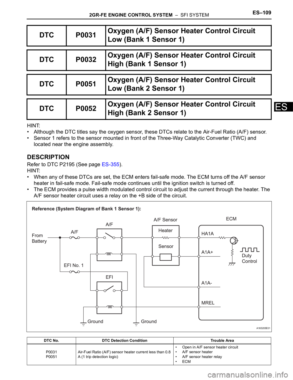
2GR-FE ENGINE CONTROL SYSTEM – SFI SYSTEMES–109
ES
HINT:
• Although the DTC titles say the oxygen sensor, these DTCs relate to the Air-Fuel Ratio (A/F) sensor.
• Sensor 1 refers to the sensor mounted in front of the Three-Way Catalytic Converter (TWC) and
located near the engine assembly.
DESCRIPTION
Refer to DTC P2195 (See page ES-355).
HINT:
• When any of these DTCs are set, the ECM enters fail-safe mode. The ECM turns off the A/F sensor
heater in fail-safe mode. Fail-safe mode continues until the ignition switch is turned off.
• The ECM provides a pulse width modulated control circuit to adjust the current through the heater. The
A/F sensor heater circuit uses a relay on the +B side of the circuit.
DTC P0031Oxygen (A/F) Sensor Heater Control Circuit
Low (Bank 1 Sensor 1)
DTC P0032Oxygen (A/F) Sensor Heater Control Circuit
High (Bank 1 Sensor 1)
DTC P0051Oxygen (A/F) Sensor Heater Control Circuit
Low (Bank 2 Sensor 1)
DTC P0052Oxygen (A/F) Sensor Heater Control Circuit
High (Bank 2 Sensor 1)
DTC No. DTC Detection Condition Trouble Area
P0031
P0051Air-Fuel Ratio (A/F) sensor heater current less than 0.8
A (1 trip detection logic)• Open in A/F sensor heater circuit
• A/F sensor heater
• A/F sensor heater relay
•ECM
A165205E01
Page 416 of 3000

ES–1102GR-FE ENGINE CONTROL SYSTEM – SFI SYSTEM
ES
HINT:
• Bank 1 refers to the bank that includes cylinder No. 1.
• Bank 2 refers to the bank that does not include cylinder No. 1.
• Sensor 1 refers to the closest sensor to the engine assembly.
• Sensor 2 refers to the furthest sensor away from the engine assembly.
MONITOR DESCRIPTION
The ECM uses information from the Air-Fuel Ratio (A/F) sensor to regulate the air-fuel ratio and keep it
close to the stoichiometric level. This maximizes the ability of the Three-Way Catalytic Converter (TWC) to
purify the exhaust gas.
The A/F sensor detects oxygen levels in the exhaust gas and transmits the information to the ECM. The
inner surface of the sensor element is exposed to the outside air. The outer surface of the sensor element
is exposed to the exhaust gas. The sensor element is made of platinum coated zirconia and includes an
integrated heating element.
The zirconia element generates small voltage when there is a large difference in the oxygen
concentrations between the exhaust gas and outside air. The platinum coating amplifies this voltage
generation.
The A/F sensor is more efficient when heated. When the exhaust gas temperature is low, the sensor
cannot generate useful voltage signals without supplementary heating. The ECM regulates the
supplementary heating using a duty-cycle approach to adjust the average current in the sensor heater
element. If the heater current is outside the normal range, the signal transmitted by the A/F sensor will be
inaccurate, as a result, the ECM will be unable to regulate air-fuel ratio properly.
When the current in the A/F sensor heater is outside the normal operating range, the ECM interprets this
as a malfunction in the sensor heater and sets a DTC.
Example:
The ECM sets DTC P0032 or P0052 when the current in the A/F sensor heater is more than 10 A.
Conversely, when the heater current is less than 0.8 A, DTC P0031 or P0051 is set.
MONITOR STRATEGY
TYPICAL ENABLING CONDITIONS
All:
P0031 and P0051:
P0032
P0052Air-Fuel Ratio (A/F) sensor heater current more than 10
A (1 trip detection logic)• Short in A/F sensor heater circuit
• A/F sensor heater
• A/F sensor heater relay
•ECM
Related DTCsP0031: A/F sensor heater (Bank 1) range check (Low current)
P0032: A/F sensor heater (Bank 1) range check (High current)
P0051: A/F sensor heater (Bank 2) range check (Low current)
P0052: A/F sensor heater (Bank 2) range check (High current)
Required sensors / components (Main) A/F sensor heater
Required sensors / components (Related) -
Frequency of operation Continuous
Duration 10 seconds
MIL operation Immediate
Sequence operation None
The monitor will run whenever these DTCs are not
presentNone
Battery voltage 10.5 V or more
Heater ON duty ratio 50% or moreDTC No. DTC Detection Condition Trouble Area
Page 417 of 3000

2GR-FE ENGINE CONTROL SYSTEM – SFI SYSTEMES–111
ES
P0032 and P0052:
TYPICAL MALFUNCTION THRESHOLDS
P0031 and P0051:
P0032 and P0052:
COMPONENT OPERATING RANGE
MONITOR RESULT
Refer to CHECKING MONITOR STATUS (See page ES-19).
WIRING DIAGRAM
Refer to DTC P2195 (See page ES-359).
INSPECTION PROCEDURE
HINT:
Read freeze frame data using the intelligent tester. The ECM records vehicle and driving condition
information as freeze frame data the moment a DTC is stored. When troubleshooting, freeze frame data
can be helpful in determining whether the vehicle was running or stopped, whether the engine was
warmed up or not, whether the air-fuel ratio was lean or rich, as well as other data recorded at the time of
a malfunction.
Time after engine starts 10 seconds or more
Time after engine starts 10 seconds or more
Heater current Less than 0.8 A
Hybrid IC high current limit port Fail
A/F sensor heater current 0.8 A or more