2007 TOYOTA SIENNA heater
[x] Cancel search: heaterPage 330 of 3000
ES–2622GR-FE ENGINE CONTROL SYSTEM – SFI SYSTEM
ES
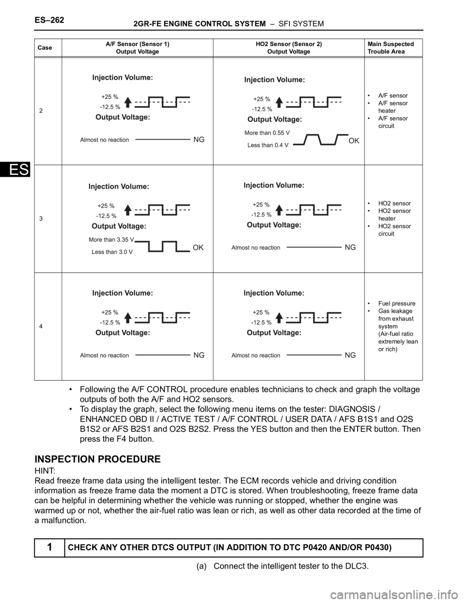
• Following the A/F CONTROL procedure enables technicians to check and graph the voltage
outputs of both the A/F and HO2 sensors.
• To display the graph, select the following menu items on the tester: DIAGNOSIS /
ENHANCED OBD II / ACTIVE TEST / A/F CONTROL / USER DATA / AFS B1S1 and O2S
B1S2 or AFS B2S1 and O2S B2S2. Press the YES button and then the ENTER button. Then
press the F4 button.
INSPECTION PROCEDURE
HINT:
Read freeze frame data using the intelligent tester. The ECM records vehicle and driving condition
information as freeze frame data the moment a DTC is stored. When troubleshooting, freeze frame data
can be helpful in determining whether the vehicle was running or stopped, whether the engine was
warmed up or not, whether the air-fuel ratio was lean or rich, as well as other data recorded at the time of
a malfunction.
(a) Connect the intelligent tester to the DLC3.
2• A/F sensor
• A/F sensor
heater
• A/F sensor
circuit
3• HO2 sensor
• HO2 sensor
heater
• HO2 sensor
circuit
4•Fuel pressure
• Gas leakage
from exhaust
system
(Air-fuel ratio
extremely lean
or rich)
1CHECK ANY OTHER DTCS OUTPUT (IN ADDITION TO DTC P0420 AND/OR P0430)
CaseA/F Sensor (Sensor 1)
Output VoltageHO2 Sensor (Sensor 2)
Output VoltageMain Suspected
Trouble Area
Page 351 of 3000

2GR-FE ENGINE CONTROL SYSTEM – SFI SYSTEMES–25
ES
Rear Oxygen Sensor Heater
$A7 $0C Multiply by 1 TimeMisfire rate for cylinder 6: Misfire counts for last/current driving cycle-
To t a l
Monitor ID Test ID Scaling Unit Description
$42 $91 Multiply by 0.001 Ohm Oxygen sensor heater resistance bank 1 sensor 2
$46 $91 Multiply by 0.004 Ohm Oxygen sensor heater resistance bank 2 sensor 2 Monitor ID Test ID Scaling Unit Description
Page 353 of 3000
2GR-FE ENGINE CONTROL SYSTEM – SFI SYSTEMES–27
ES
Contents:
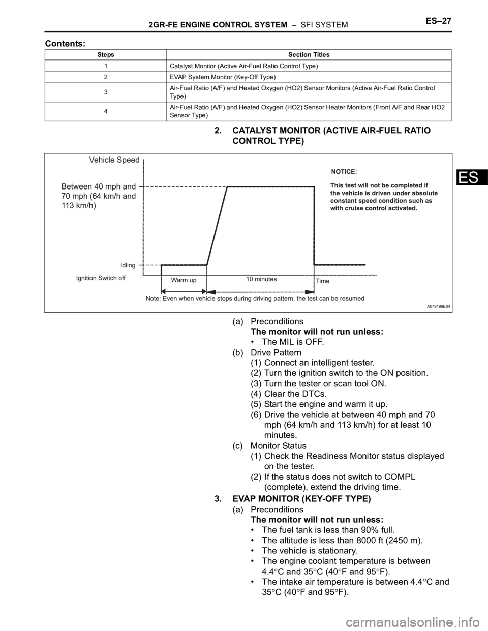
2. CATALYST MONITOR (ACTIVE AIR-FUEL RATIO
CONTROL TYPE)
(a) Preconditions
The monitor will not run unless:
• The MIL is OFF.
(b) Drive Pattern
(1) Connect an intelligent tester.
(2) Turn the ignition switch to the ON position.
(3) Turn the tester or scan tool ON.
(4) Clear the DTCs.
(5) Start the engine and warm it up.
(6) Drive the vehicle at between 40 mph and 70
mph (64 km/h and 113 km/h) for at least 10
minutes.
(c) Monitor Status
(1) Check the Readiness Monitor status displayed
on the tester.
(2) If the status does not switch to COMPL
(complete), extend the driving time.
3. EVAP MONITOR (KEY-OFF TYPE)
(a) Preconditions
The monitor will not run unless:
• The fuel tank is less than 90% full.
• The altitude is less than 8000 ft (2450 m).
• The vehicle is stationary.
• The engine coolant temperature is between
4.4
C and 35C (40F and 95F).
• The intake air temperature is between 4.4
C and
35
C (40F and 95F).
Steps Section Titles
1 Catalyst Monitor (Active Air-Fuel Ratio Control Type)
2 EVAP System Monitor (Key-Off Type)
3Air-Fuel Ratio (A/F) and Heated Oxygen (HO2) Sensor Monitors (Active Air-Fuel Ratio Control
Ty p e )
4Air-Fuel Ratio (A/F) and Heated Oxygen (HO2) Sensor Heater Monitors (Front A/F and Rear HO2
Sensor Type)
A079199E84
Page 355 of 3000
2GR-FE ENGINE CONTROL SYSTEM – SFI SYSTEMES–29
ES
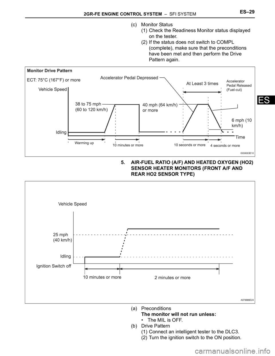
(c) Monitor Status
(1) Check the Readiness Monitor status displayed
on the tester.
(2) If the status does not switch to COMPL
(complete), make sure that the preconditions
have been met and then perform the Drive
Pattern again.
5. AIR-FUEL RATIO (A/F) AND HEATED OXYGEN (HO2)
SENSOR HEATER MONITORS (FRONT A/F AND
REAR HO2 SENSOR TYPE)
(a) Preconditions
The monitor will not run unless:
• The MIL is OFF.
(b) Drive Pattern
(1) Connect an intelligent tester to the DLC3.
(2) Turn the ignition switch to the ON position.
G039003E10
A078886E24
Page 369 of 3000

2GR-FE ENGINE CONTROL SYSTEM – SFI SYSTEMES–51
ES
FAIL-SAFE CHART
If any of the following DTCs are set, the ECM enters fail-safe
mode to allow the vehicle to be driven temporarily.
HINT:
• *1: The vehicle can be driven slowly when the accelerator
pedal is depressed firmly and slowly. If the accelerator
pedal is depressed quickly, the vehicle may speed up and
slow down erratically.
• *2: Misfire related fail-safe operations occur when catalyst
overheat malfunctions occur.
DTCs Components Fail-Safe OperationsFail-Safe Deactivation
Conditions
P0031, P0032, P0051 and P0052Air-Fuel Ratio (A/F) Sensor
HeaterECM turns off A/F sensor heater Ignition switch off
P0037, P0038, P0057 and P0058Heated Oxygen (HO2) Sensor
HeaterECM turns off HO2 sensor heater Ignition switch off
P0100, P0102 and P0103 Mass Air Flow (MAF) MeterECM calculates ignition timing
according to engine speed and
throttle valve positionPass condition detected
P0110, P0112 and P0113Intake Air Temperature (IAT)
SensorECM estimates IAT to be 20
C
(68
F)Pass condition detected
P0115, P0117 and P0118Engine Coolant Temperature
(ECT) SensorECM estimates ECT to be 80
C
(176
F)Pass condition detected
P0120, P0121, P0122, P0123,
P0220, P0222, P0223, P0604,
P0606, P0607, P0657, P2102,
P2103, P2111, P2112, P2118,
P2119 and P2135Electronic Throttle Control
System (ETCS)ECM cuts off throttle actuator
current and throttle valve returned
to 6.5
throttle position by return
spring
ECM then adjusts engine output
by controlling fuel injection
(intermittent fuel-cut) and ignition
timing in accordance with
accelerator pedal opening angle,
to allow vehicle to continue at
minimal speed*1Pass condition detected and then
ignition switch turned off
P0300, P0301, P0302, P0303,
P0304, P0305 and P0306*2• Fuel injector
• Electronic Throttle Control
System (ETCS)When misfire occurs, fuel cut is
performed for catalyst overheat
malfunction prevention
• During normal load and
normal engine speed (MIL is
blinking)
- Fuel cut is performed on
malfunctioning cylinder
• During high load and high
engine speed (MIL is
blinking)
- Throttle valve opening angle
control is performed
- All cylinder fuel cut or
malfunction cylinder fuel cutPass condition detected and then
ignition switch turned OFF
P0327, P0328, P0332 and P0333 Knock SensorECM sets ignition timing to
maximum retardIgnition switch off
P0351 to P0356 Igniter ECM cuts fuel Pass condition detected
P2120, P2121, P2122, P2123,
P2125, P2127, P2128 and P2138Accelerator Pedal Position (APP)
SensorAPP sensor has 2 sensor circuits:
Main and Sub
If either of circuits malfunctions,
ECM controls engine using the
other circuit
If both of circuits malfunction,
ECM regards accelerator pedal
as being released. As a result,
throttle valve is closed and engine
idlesPass condition detected and then
ignition switch turned off
Page 372 of 3000
ES–662GR-FE ENGINE CONTROL SYSTEM – SFI SYSTEM
ES
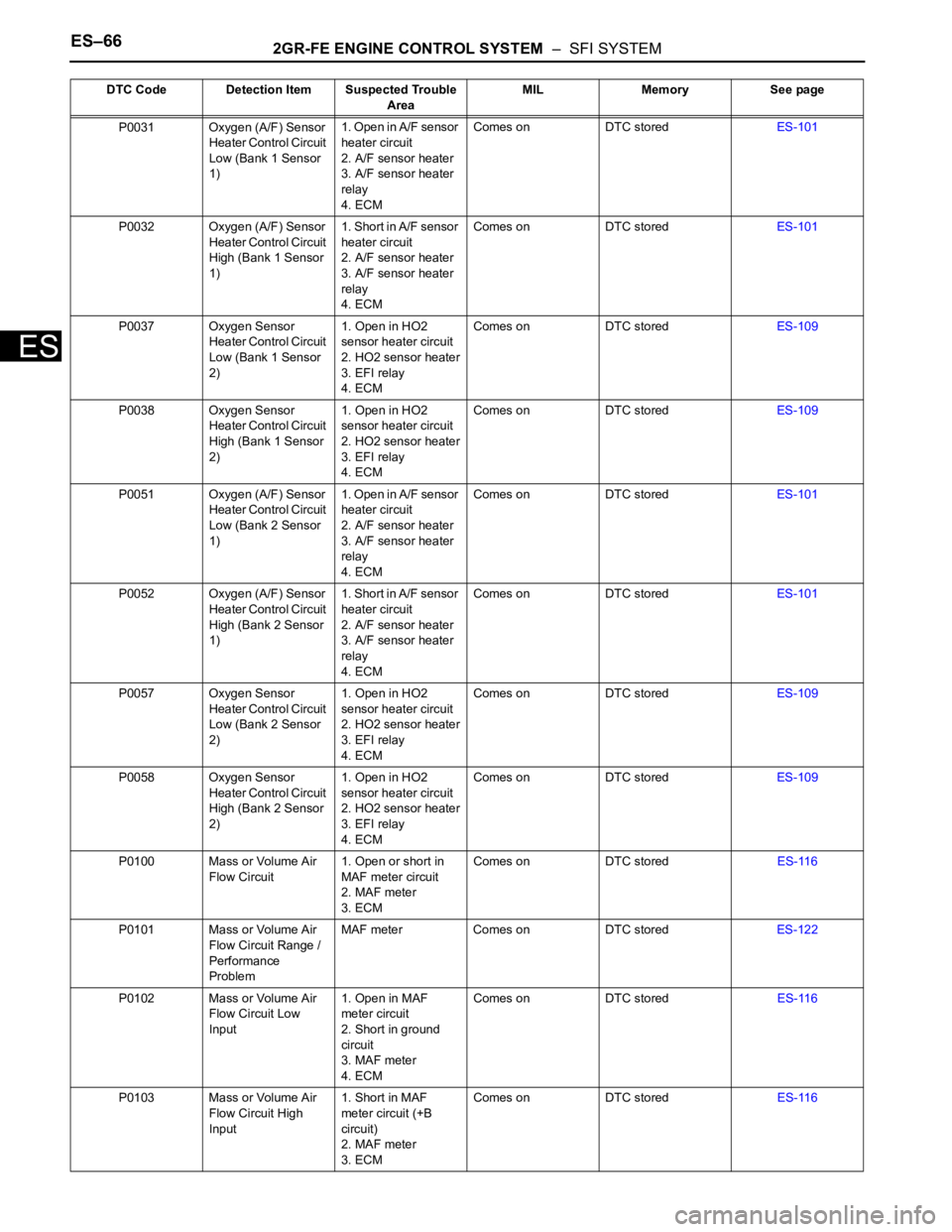
P0031 Oxygen (A/F) Sensor
Heater Control Circuit
Low (Bank 1 Sensor
1)1. Open in A/F sensor
heater circuit
2. A/F sensor heater
3. A/F sensor heater
relay
4. ECMComes on DTC storedES-101
P0032 Oxygen (A/F) Sensor
Heater Control Circuit
High (Bank 1 Sensor
1)1. Short in A/F sensor
heater circuit
2. A/F sensor heater
3. A/F sensor heater
relay
4. ECMComes on DTC storedES-101
P0037 Oxygen Sensor
Heater Control Circuit
Low (Bank 1 Sensor
2)1. Open in HO2
sensor heater circuit
2. HO2 sensor heater
3. EFI relay
4. ECMComes on DTC storedES-109
P0038 Oxygen Sensor
Heater Control Circuit
High (Bank 1 Sensor
2)1. Open in HO2
sensor heater circuit
2. HO2 sensor heater
3. EFI relay
4. ECMComes on DTC storedES-109
P0051 Oxygen (A/F) Sensor
Heater Control Circuit
Low (Bank 2 Sensor
1)1. Open in A/F sensor
heater circuit
2. A/F sensor heater
3. A/F sensor heater
relay
4. ECMComes on DTC storedES-101
P0052 Oxygen (A/F) Sensor
Heater Control Circuit
High (Bank 2 Sensor
1)1. Short in A/F sensor
heater circuit
2. A/F sensor heater
3. A/F sensor heater
relay
4. ECMComes on DTC storedES-101
P0057 Oxygen Sensor
Heater Control Circuit
Low (Bank 2 Sensor
2)1. Open in HO2
sensor heater circuit
2. HO2 sensor heater
3. EFI relay
4. ECMComes on DTC storedES-109
P0058 Oxygen Sensor
Heater Control Circuit
High (Bank 2 Sensor
2)1. Open in HO2
sensor heater circuit
2. HO2 sensor heater
3. EFI relay
4. ECMComes on DTC storedES-109
P0100 Mass or Volume Air
Flow Circuit1. Open or short in
MAF meter circuit
2. MAF meter
3. ECMComes on DTC storedES-116
P0101 Mass or Volume Air
Flow Circuit Range /
Performance
ProblemMAF meter Comes on DTC storedES-122
P0102 Mass or Volume Air
Flow Circuit Low
Input1. Open in MAF
meter circuit
2. Short in ground
circuit
3. MAF meter
4. ECMComes on DTC storedES-116
P0103 Mass or Volume Air
Flow Circuit High
Input1. Short in MAF
meter circuit (+B
circuit)
2. MAF meter
3. ECMComes on DTC storedES-116 DTC Code Detection Item Suspected Trouble
AreaMIL Memory See page
Page 374 of 3000
ES–682GR-FE ENGINE CONTROL SYSTEM – SFI SYSTEM
ES
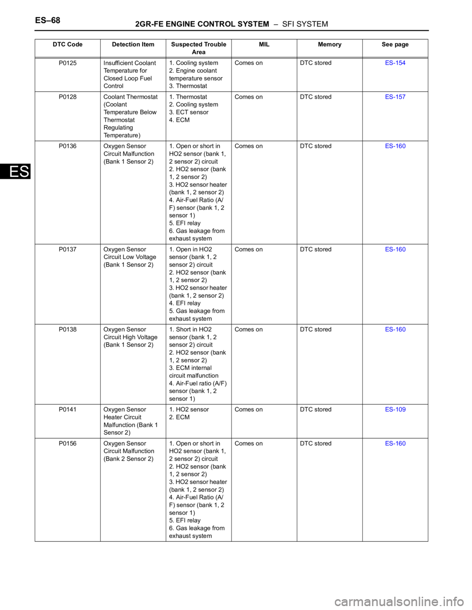
P0125 Insufficient Coolant
Temperature for
Closed Loop Fuel
Control1. Cooling system
2. Engine coolant
temperature sensor
3. ThermostatComes on DTC storedES-154
P0128 Coolant Thermostat
(Coolant
Temperature Below
Thermostat
Regulating
Temperature)1. Thermostat
2. Cooling system
3. ECT sensor
4. ECMComes on DTC storedES-157
P0136 Oxygen Sensor
Circuit Malfunction
(Bank 1 Sensor 2)1. Open or short in
HO2 sensor (bank 1,
2 sensor 2) circuit
2. HO2 sensor (bank
1, 2 sensor 2)
3. HO2 sensor heater
(bank 1, 2 sensor 2)
4. Air-Fuel Ratio (A/
F) sensor (bank 1, 2
sensor 1)
5. EFI relay
6. Gas leakage from
exhaust systemComes on DTC storedES-160
P0137 Oxygen Sensor
Circuit Low Voltage
(Bank 1 Sensor 2)1. Open in HO2
sensor (bank 1, 2
sensor 2) circuit
2. HO2 sensor (bank
1, 2 sensor 2)
3. HO2 sensor heater
(bank 1, 2 sensor 2)
4. EFI relay
5. Gas leakage from
exhaust systemComes on DTC storedES-160
P0138 Oxygen Sensor
Circuit High Voltage
(Bank 1 Sensor 2)1. Short in HO2
sensor (bank 1, 2
sensor 2) circuit
2. HO2 sensor (bank
1, 2 sensor 2)
3. ECM internal
circuit malfunction
4. Air-Fuel ratio (A/F)
sensor (bank 1, 2
sensor 1)Comes on DTC storedES-160
P0141 Oxygen Sensor
Heater Circuit
Malfunction (Bank 1
Sensor 2)1. HO2 sensor
2. ECMComes on DTC storedES-109
P0156 Oxygen Sensor
Circuit Malfunction
(Bank 2 Sensor 2)1. Open or short in
HO2 sensor (bank 1,
2 sensor 2) circuit
2. HO2 sensor (bank
1, 2 sensor 2)
3. HO2 sensor heater
(bank 1, 2 sensor 2)
4. Air-Fuel Ratio (A/
F) sensor (bank 1, 2
sensor 1)
5. EFI relay
6. Gas leakage from
exhaust systemComes on DTC storedES-160 DTC Code Detection Item Suspected Trouble
AreaMIL Memory See page
Page 375 of 3000
2GR-FE ENGINE CONTROL SYSTEM – SFI SYSTEMES–69
ES
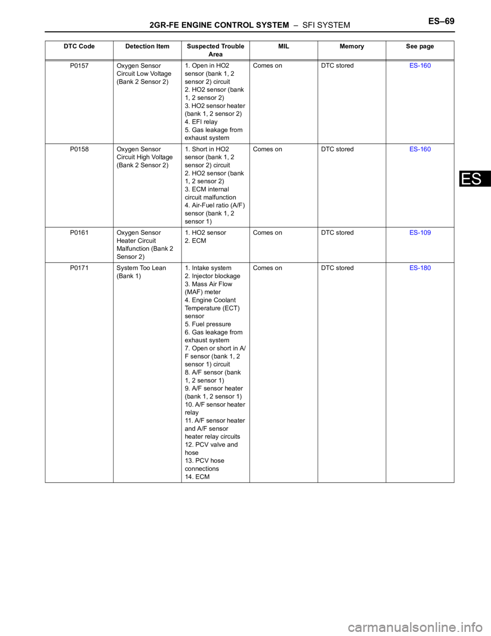
P0157 Oxygen Sensor
Circuit Low Voltage
(Bank 2 Sensor 2)1. Open in HO2
sensor (bank 1, 2
sensor 2) circuit
2. HO2 sensor (bank
1, 2 sensor 2)
3. HO2 sensor heater
(bank 1, 2 sensor 2)
4. EFI relay
5. Gas leakage from
exhaust systemComes on DTC storedES-160
P0158 Oxygen Sensor
Circuit High Voltage
(Bank 2 Sensor 2)1. Short in HO2
sensor (bank 1, 2
sensor 2) circuit
2. HO2 sensor (bank
1, 2 sensor 2)
3. ECM internal
circuit malfunction
4. Air-Fuel ratio (A/F)
sensor (bank 1, 2
sensor 1)Comes on DTC storedES-160
P0161 Oxygen Sensor
Heater Circuit
Malfunction (Bank 2
Sensor 2)1. HO2 sensor
2. ECMComes on DTC storedES-109
P0171 System Too Lean
(Bank 1)1. Intake system
2. Injector blockage
3. Mass Air Flow
(MAF) meter
4. Engine Coolant
Temperature (ECT)
sensor
5. Fuel pressure
6. Gas leakage from
exhaust system
7. Open or short in A/
F sensor (bank 1, 2
sensor 1) circuit
8. A/F sensor (bank
1, 2 sensor 1)
9. A/F sensor heater
(bank 1, 2 sensor 1)
10. A/F sensor heater
relay
11. A/F sensor heater
and A/F sensor
heater relay circuits
12. PCV valve and
hose
13. PCV hose
connections
14. ECMComes on DTC storedES-180 DTC Code Detection Item Suspected Trouble
AreaMIL Memory See page