Page 2576 of 3000

BC–36BRAKE CONTROL – ANTI-LOCK BRAKE SYSTEM
BC
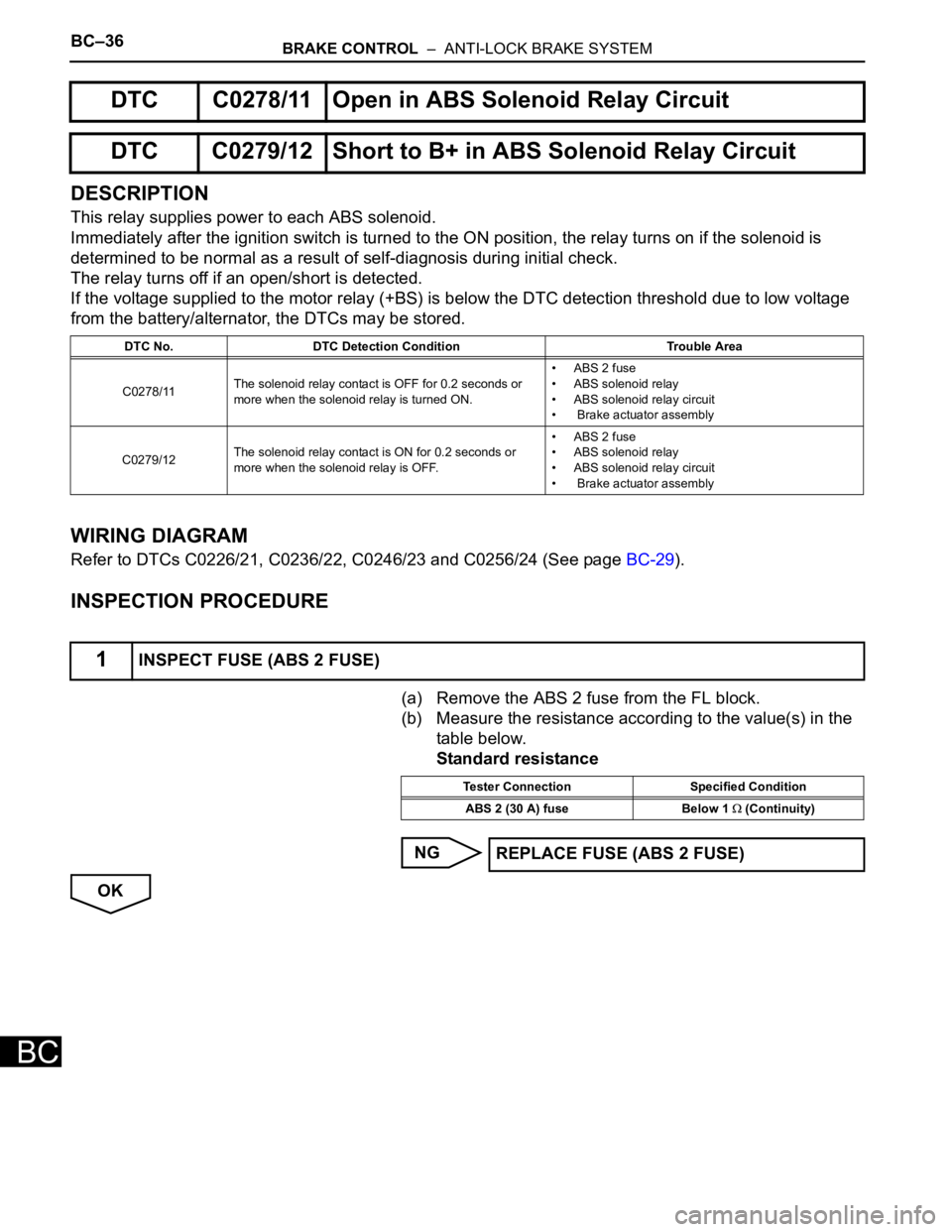
DESCRIPTION
This relay supplies power to each ABS solenoid.
Immediately after the ignition switch is turned to the ON position, the relay turns on if the solenoid is
determined to be normal as a result of self-diagnosis during initial check.
The relay turns off if an open/short is detected.
If the voltage supplied to the motor relay (+BS) is below the DTC detection threshold due to low voltage
from the battery/alternator, the DTCs may be stored.
WIRING DIAGRAM
Refer to DTCs C0226/21, C0236/22, C0246/23 and C0256/24 (See page BC-29).
INSPECTION PROCEDURE
(a) Remove the ABS 2 fuse from the FL block.
(b) Measure the resistance according to the value(s) in the
table below.
Standard resistance
NG
OK
DTC C0278/11 Open in ABS Solenoid Relay Circuit
DTC C0279/12 Short to B+ in ABS Solenoid Relay Circuit
DTC No. DTC Detection Condition Trouble Area
C0278/11The solenoid relay contact is OFF for 0.2 seconds or
more when the solenoid relay is turned ON.• ABS 2 fuse
• ABS solenoid relay
• ABS solenoid relay circuit
• Brake actuator assembly
C0279/12The solenoid relay contact is ON for 0.2 seconds or
more when the solenoid relay is OFF.• ABS 2 fuse
• ABS solenoid relay
• ABS solenoid relay circuit
• Brake actuator assembly
1INSPECT FUSE (ABS 2 FUSE)
Tester Connection Specified Condition
ABS 2 (30 A) fuse Below 1
(Continuity)
REPLACE FUSE (ABS 2 FUSE)
Page 2582 of 3000

BRAKE CONTROL – ANTI-LOCK BRAKE SYSTEMBC–39
BC
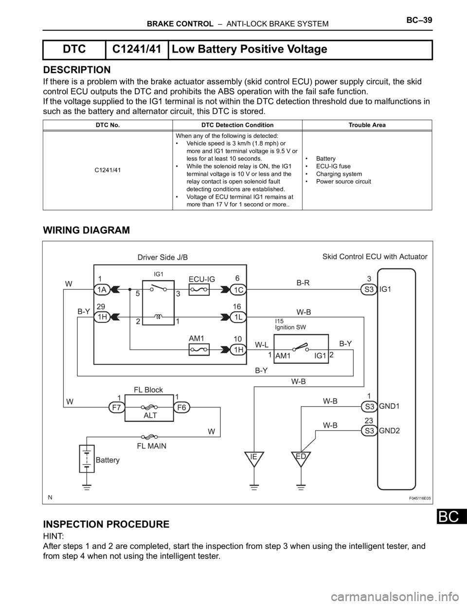
DESCRIPTION
If there is a problem with the brake actuator assembly (skid control ECU) power supply circuit, the skid
control ECU outputs the DTC and prohibits the ABS operation with the fail safe function.
If the voltage supplied to the IG1 terminal is not within the DTC detection threshold due to malfunctions in
such as the battery and alternator circuit, this DTC is stored.
WIRING DIAGRAM
INSPECTION PROCEDURE
HINT:
After steps 1 and 2 are completed, start the inspection from step 3 when using the intelligent tester, and
from step 4 when not using the intelligent tester.
DTC C1241/41 Low Battery Positive Voltage
DTC No. DTC Detection Condition Trouble Area
C1241/41When any of the following is detected:
• Vehicle speed is 3 km/h (1.8 mph) or
more and IG1 terminal voltage is 9.5 V or
less for at least 10 seconds.
• While the solenoid relay is ON, the IG1
terminal voltage is 10 V or less and the
relay contact is open solenoid fault
detecting conditions are established.
• Voltage of ECU terminal IG1 remains at
more than 17 V for 1 second or more..• Battery
•ECU-IG fuse
• Charging system
• Power source circuit
F045116E05
Page 2893 of 3000
AC–150AIR CONDITIONING – AIR CONDITIONING SYSTEM (for Automatic Air Conditioning Sys-
tem)
AC
DESCRIPTION
The main power source is supplied to the A/C amplifier when the ignition switch is turned to the ON
position.
The power source is used for operating the A/C amplifier and servo motor, etc.
WIRING DIAGRAM
INSPECTION PROCEDURE
HINT:
Start the engine before inspection. Check the IG1 relay or battery if the engine does not start.
(a) Remove the HTR fuse from the driver side junction
block.
(b) Measure the resistance according to the value(s) in the
table below.
Standard resistance
NG
IG Power Source Circuit
1INSPECT FUSE (HTR)
E130466E04
Tester Item Condition Specified Condition
HTR fuse Always Below 1
REPLACE FUSE (HTR)
Page 2896 of 3000
AIR CONDITIONING – AIR CONDITIONING SYSTEM (for Automatic Air Conditioning Sys-
tem)AC–153
AC
DESCRIPTION
This circuit supplies power to the A/C amplifier and the illumination for the clock.
WIRING DIAGRAM
INSPECTION PROCEDURE
(a) Remove the ECU ACC fuse from the engine room relay
block.
(b) Measure the resistance according to the value(s) in the
table below.
Standard resistance
NG
OK
ACC Power Source Circuit
1INSPECT FUSE (ECU ACC)
E146556E02
Tester Item Condition Specified Condition
ECU ACC Fuse Always Below 1
REPLACE FUSE (ECU ACC)
Page 2898 of 3000
AIR CONDITIONING – AIR CONDITIONING SYSTEM (for Automatic Air Conditioning Sys-
tem)AC–155
AC
DESCRIPTION
This is the back-up power source for the A/C amplifier. Power is supplied even when the ignition switch is
off and is used for diagnostic trouble code memory, etc.
WIRING DIAGRAM
INSPECTION PROCEDURE
(a) Remove the ECU-B fuse from the engine room junction
block.
(b) Measure the resistance according to the value(s) in the
table below.
Standard resistance
NG
OK
Back-up Power Source Circuit
1INSPECT FUSE (ECU-B)
E146556E03
Tester Item Condition Specified Condition
ECU-B Fuse Always Below 1
REPLACE FUSE (ECU-B)