Page 242 of 3000

THEFT DETERRENT – THEFT DETERRENT SYSTEMTD–9
TD
• The theft deterrent system switches to the
alarm sounding state. Under this condition,
the theft deterrent system is controlling the
alarm rather than the panic alarm control. In
order to cancel this alarm, refer to the theft
deterrent system alarm sounding state
cancellation procedure. (This condition is
common both to active arming mode to
passive arming mode.)
HINT:
Active arming mode: See ACTIVE ARMING
MODE.
Passive arming mode: See PASSIVE ARMING
MODE.
7. SECURITY INDICATOR OUTPUT
(a) The multiplex network body ECU outputs a signal to
light up the security indicator, according to the state
of the theft deterrent system. However, some of the
actual lighting conditions of the security indicator
are different from the output signals of the multiplex
network body ECU.
Output:
Blinking cycle:
HINT:
• *: The above condition is common both to active
arming mode and to passive arming mode.
• When the immobiliser system is set, the security
indicator blinks during both the disarmed state
and the armed state, due to the output signals
from the immobiliser system.
State of Theft Deterrent System*Security Indicator
Output Signals from Body ECU Actual Lighting Condition
Disarmed state (1), (2) OFFOFF (Immobiliser system unset)
BLINKING (Immobiliser system set)
Arming preparation state ON ON
Armed state OFF BLINKING
Alarm sounding state ON ON
Time Security Indicator
0.2 sec. ON
1.8 sec. OFF
Page 322 of 3000
ES–2542GR-FE ENGINE CONTROL SYSTEM – SFI SYSTEM
ES
Exhaust Camshaft Sensor Range Check (Low voltage):
Exhaust Camshaft Sensor Range Check (High voltage):
WIRING DIAGRAM
Refer to DTC P0335 (See page ES-222).
INSPECTION PROCEDURE
HINT:
Read freeze frame data using the intelligent tester. The ECM records vehicle and driving condition
information as freeze frame data the moment a DTC is stored. When troubleshooting, freeze frame data
can be helpful in determining whether the vehicle was running or stopped, whether the engine was
warmed up or not, whether the air-fuel ratio was lean or rich, as well as other data recorded at the time of
a malfunction.
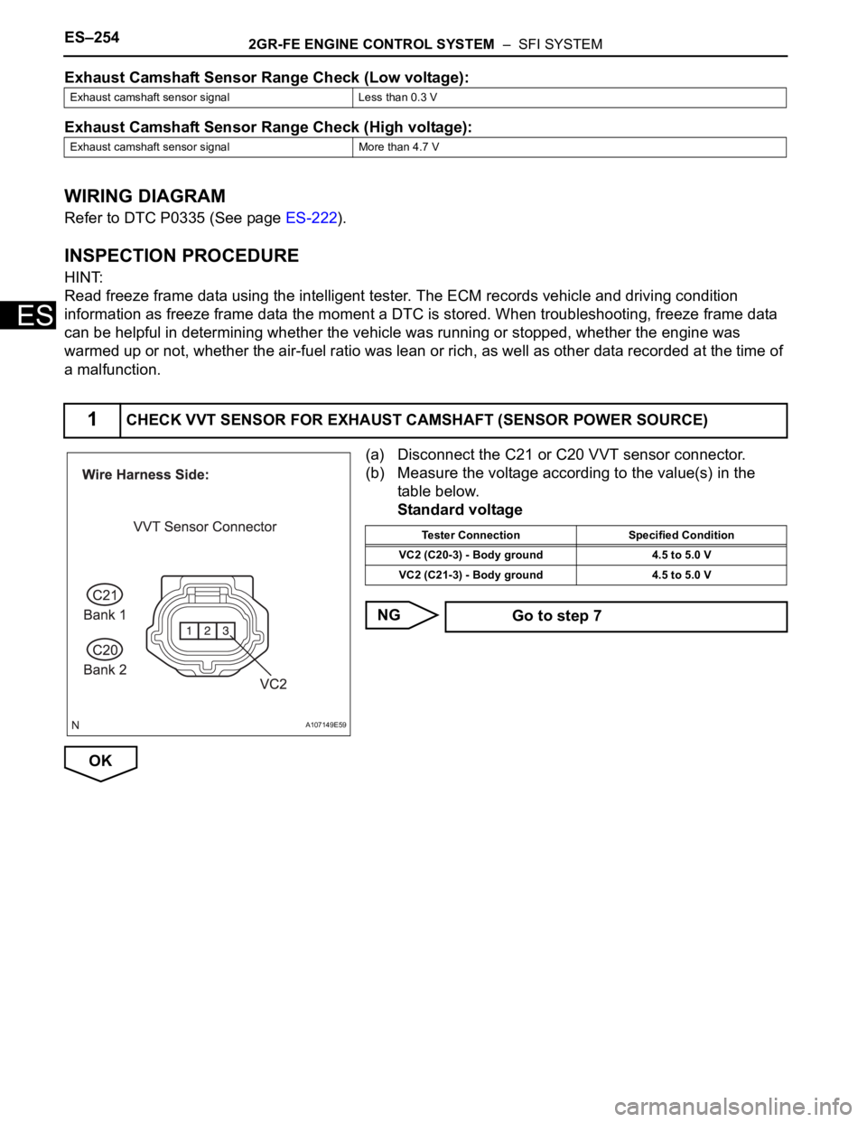
(a) Disconnect the C21 or C20 VVT sensor connector.
(b) Measure the voltage according to the value(s) in the
table below.
Standard voltage
NG
OK
Exhaust camshaft sensor signal Less than 0.3 V
Exhaust camshaft sensor signal More than 4.7 V
1CHECK VVT SENSOR FOR EXHAUST CAMSHAFT (SENSOR POWER SOURCE)
A107149E59
Tester Connection Specified Condition
VC2 (C20-3) - Body ground 4.5 to 5.0 V
VC2 (C21-3) - Body ground 4.5 to 5.0 V
Go to step 7
Page 328 of 3000
ES–2602GR-FE ENGINE CONTROL SYSTEM – SFI SYSTEM
ES
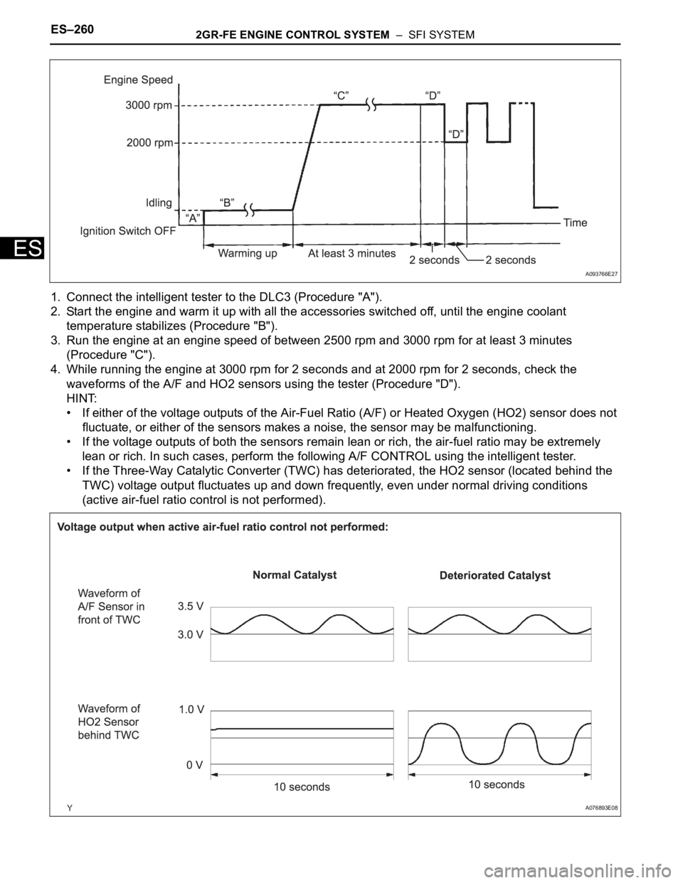
1. Connect the intelligent tester to the DLC3 (Procedure "A").
2. Start the engine and warm it up with all the accessories switched off, until the engine coolant
temperature stabilizes (Procedure "B").
3. Run the engine at an engine speed of between 2500 rpm and 3000 rpm for at least 3 minutes
(Procedure "C").
4. While running the engine at 3000 rpm for 2 seconds and at 2000 rpm for 2 seconds, check the
waveforms of the A/F and HO2 sensors using the tester (Procedure "D").
HINT:
• If either of the voltage outputs of the Air-Fuel Ratio (A/F) or Heated Oxygen (HO2) sensor does not
fluctuate, or either of the sensors makes a noise, the sensor may be malfunctioning.
• If the voltage outputs of both the sensors remain lean or rich, the air-fuel ratio may be extremely
lean or rich. In such cases, perform the following A/F CONTROL using the intelligent tester.
• If the Three-Way Catalytic Converter (TWC) has deteriorated, the HO2 sensor (located behind the
TWC) voltage output fluctuates up and down frequently, even under normal driving conditions
(active air-fuel ratio control is not performed).
A093766E27
A076893E08
Page 329 of 3000
2GR-FE ENGINE CONTROL SYSTEM – SFI SYSTEMES–261
ES
1. A/F CONTROL
HINT:
Intelligent tester only:
Malfunctioning areas can be identified by performing the A/F CONTROL function provided in the
ACTIVE TEST. The A/F CONTROL function can help to determine whether the Air-Fuel Ratio (A/F)
sensor, Heated Oxygen (HO2) sensor and other potential trouble areas are malfunctioning.
The following instructions describe how to conduct the A/F CONTROL operation using an intelligent
tester.
(a) Connect the intelligent tester to the DLC3.
(b) Start the engine and turn the tester on.
(c) Warm up the engine at an engine speed of 2500 rpm for approximately 90 seconds.
(d) On the tester, select the following menu items: DIAGNOSIS / ENHANCED OBD II / ACTIVE
TEST / A/F CONTROL.
(e) Perform the A/F CONTROL operation with the engine in an idling condition (press the RIGHT or
LEFT button to change the fuel injection volume).
(f) Monitor the voltage outputs of the A/F and HO2 sensors (AFS B1S1 and O2S B1S2 or AFS
B2S1 and O2S B2S2) displayed on the tester.
HINT:
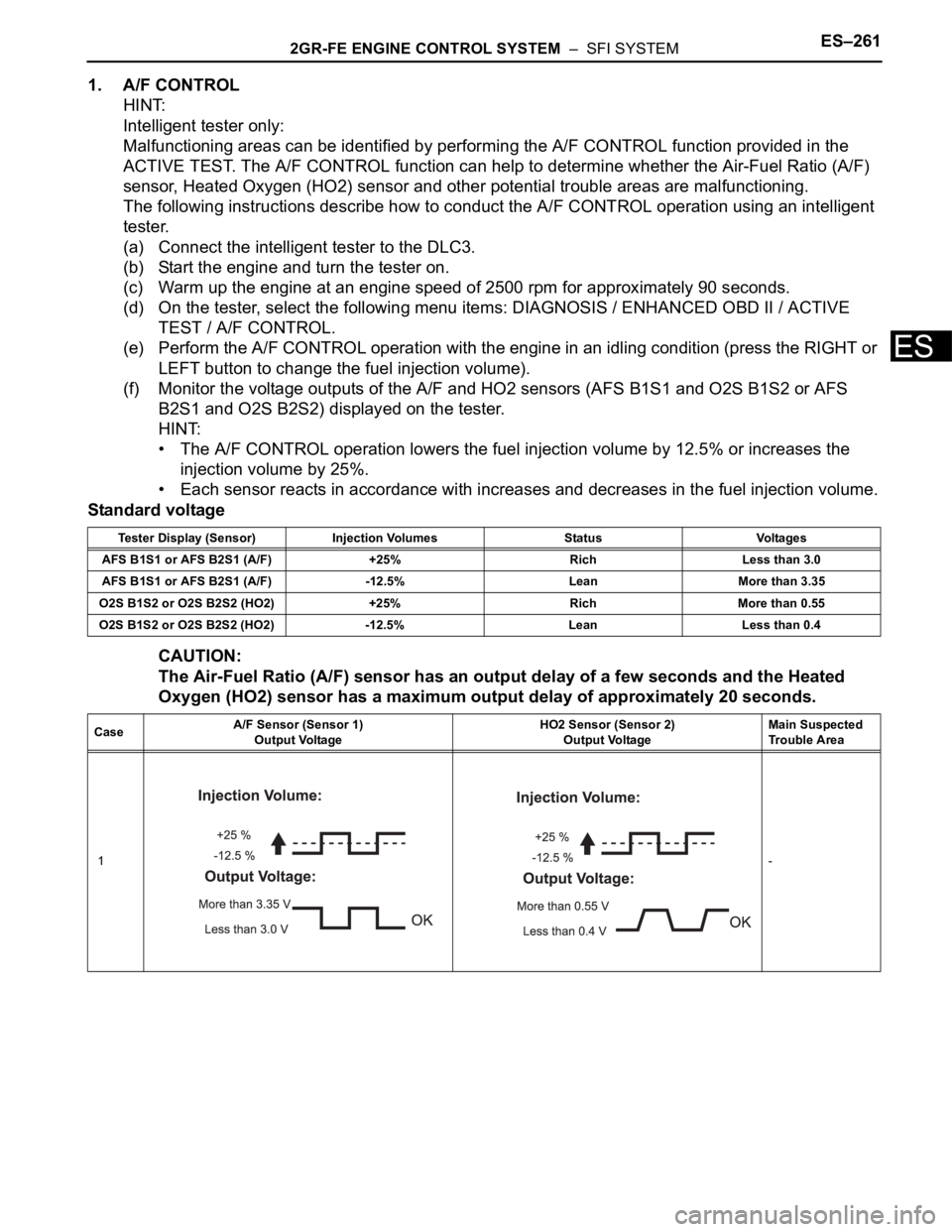
• The A/F CONTROL operation lowers the fuel injection volume by 12.5% or increases the
injection volume by 25%.
• Each sensor reacts in accordance with increases and decreases in the fuel injection volume.
Standard voltage
CAUTION:
The Air-Fuel Ratio (A/F) sensor has an output delay of a few seconds and the Heated
Oxygen (HO2) sensor has a maximum output delay of approximately 20 seconds.
Tester Display (Sensor) Injection Volumes Status Voltages
AFS B1S1 or AFS B2S1 (A/F) +25% Rich Less than 3.0
AFS B1S1 or AFS B2S1 (A/F) -12.5% Lean More than 3.35
O2S B1S2 or O2S B2S2 (HO2) +25% Rich More than 0.55
O2S B1S2 or O2S B2S2 (HO2) -12.5% Lean Less than 0.4
CaseA/F Sensor (Sensor 1)
Output VoltageHO2 Sensor (Sensor 2)
Output VoltageMain Suspected
Trouble Area
1-
Page 330 of 3000
ES–2622GR-FE ENGINE CONTROL SYSTEM – SFI SYSTEM
ES
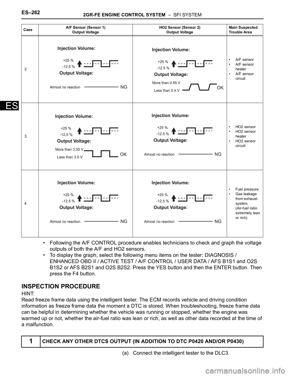
• Following the A/F CONTROL procedure enables technicians to check and graph the voltage
outputs of both the A/F and HO2 sensors.
• To display the graph, select the following menu items on the tester: DIAGNOSIS /
ENHANCED OBD II / ACTIVE TEST / A/F CONTROL / USER DATA / AFS B1S1 and O2S
B1S2 or AFS B2S1 and O2S B2S2. Press the YES button and then the ENTER button. Then
press the F4 button.
INSPECTION PROCEDURE
HINT:
Read freeze frame data using the intelligent tester. The ECM records vehicle and driving condition
information as freeze frame data the moment a DTC is stored. When troubleshooting, freeze frame data
can be helpful in determining whether the vehicle was running or stopped, whether the engine was
warmed up or not, whether the air-fuel ratio was lean or rich, as well as other data recorded at the time of
a malfunction.
(a) Connect the intelligent tester to the DLC3.
2• A/F sensor
• A/F sensor
heater
• A/F sensor
circuit
3• HO2 sensor
• HO2 sensor
heater
• HO2 sensor
circuit
4•Fuel pressure
• Gas leakage
from exhaust
system
(Air-fuel ratio
extremely lean
or rich)
1CHECK ANY OTHER DTCS OUTPUT (IN ADDITION TO DTC P0420 AND/OR P0430)
CaseA/F Sensor (Sensor 1)
Output VoltageHO2 Sensor (Sensor 2)
Output VoltageMain Suspected
Trouble Area
Page 331 of 3000
2GR-FE ENGINE CONTROL SYSTEM – SFI SYSTEMES–263
ES
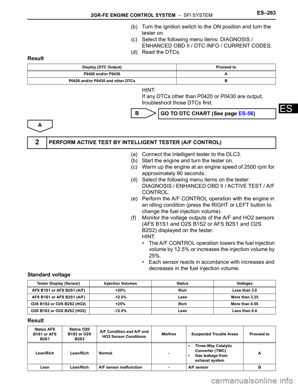
(b) Turn the ignition switch to the ON position and turn the
tester on.
(c) Select the following menu items: DIAGNOSIS /
ENHANCED OBD II / DTC INFO / CURRENT CODES.
(d) Read the DTCs.
Result
HINT:
If any DTCs other than P0420 or P0430 are output,
troubleshoot those DTCs first.
B
A
(a) Connect the intelligent tester to the DLC3.
(b) Start the engine and turn the tester on.
(c) Warm up the engine at an engine speed of 2500 rpm for
approximately 90 seconds.
(d) Select the following menu items on the tester:
DIAGNOSIS / ENHANCED OBD II / ACTIVE TEST / A/F
CONTROL.
(e) Perform the A/F CONTROL operation with the engine in
an idling condition (press the RIGHT or LEFT button to
change the fuel injection volume).
(f) Monitor the voltage outputs of the A/F and HO2 sensors
(AFS B1S1 and O2S B1S2 or AFS B2S1 and O2S
B2S2) displayed on the tester.
HINT:
• The A/F CONTROL operation lowers the fuel injection
volume by 12.5% or increases the injection volume by
25%.
• Each sensor reacts in accordance with increases and
decreases in the fuel injection volume.
Standard voltage
Result
Display (DTC Output) Proceed to
P0420 and/or P0430 A
P0420 and/or P0430 and other DTCs B
GO TO DTC CHART (See page ES-56)
2PERFORM ACTIVE TEST BY INTELLIGENT TESTER (A/F CONTROL)
Tester Display (Sensor) Injection Volumes Status Voltages
AFS B1S1 or AFS B2S1 (A/F) +25% Rich Less than 3.0
AFS B1S1 or AFS B2S1 (A/F) -12.5% Lean More than 3.35
O2S B1S2 or O2S B2S2 (HO2) +25% Rich More than 0.55
O2S B1S2 or O2S B2S2 (HO2) -12.5% Lean Less than 0.4
Status AFS
B1S1 or AFS
B2S1Status O2S
B1S2 or O2S
B2S2A/F Condition and A/F and
HO2 Sensor ConditionsMisfires Suspected Trouble Areas Proceed to
Lean/Rich Lean/Rich Normal -• Three-Way Catalytic
Converter (TWC)
• Gas leakage from
exhaust systemA
Lean Lean/Rich A/F sensor malfunction - A/F sensor B
Page 335 of 3000
2GR-FE ENGINE CONTROL SYSTEM – SFI SYSTEMES–407
ES
(a) Start the engine.
(b) Disconnect the vacuum hose from the air cleaner cap.
(c) Check that the disconnected port located on the vacuum
tank applies suction to your finger.
OK:
Vacuum pressure exists.
(d) Reconnect the vacuum hose.
NG
OK
(a) Connect the oscilloscope between terminals ACM and
E1 of the E9 and E11 ECM connectors.
(b) Warm up the engine to normal operating temperature.
(c) Turn the A/C switch on.
(d) Measure the voltage according to the value(s) in the
table below.
Standard voltage
OK
NG
2CHECK VACUUM
G041079
CHECK AND REPLACE VACUUM SOURCE
AND HOSES
3INSPECT ECM
A114640E06
Condition Voltage
Shift position is D, and engine speed is 850 rpm
or lessPulse generation
Shift position is D, and engine speed is 950 rpm
or more9 to 14 V
Shift position is P 9 to 14 V
Go to step 9
Page 353 of 3000
2GR-FE ENGINE CONTROL SYSTEM – SFI SYSTEMES–27
ES
Contents:
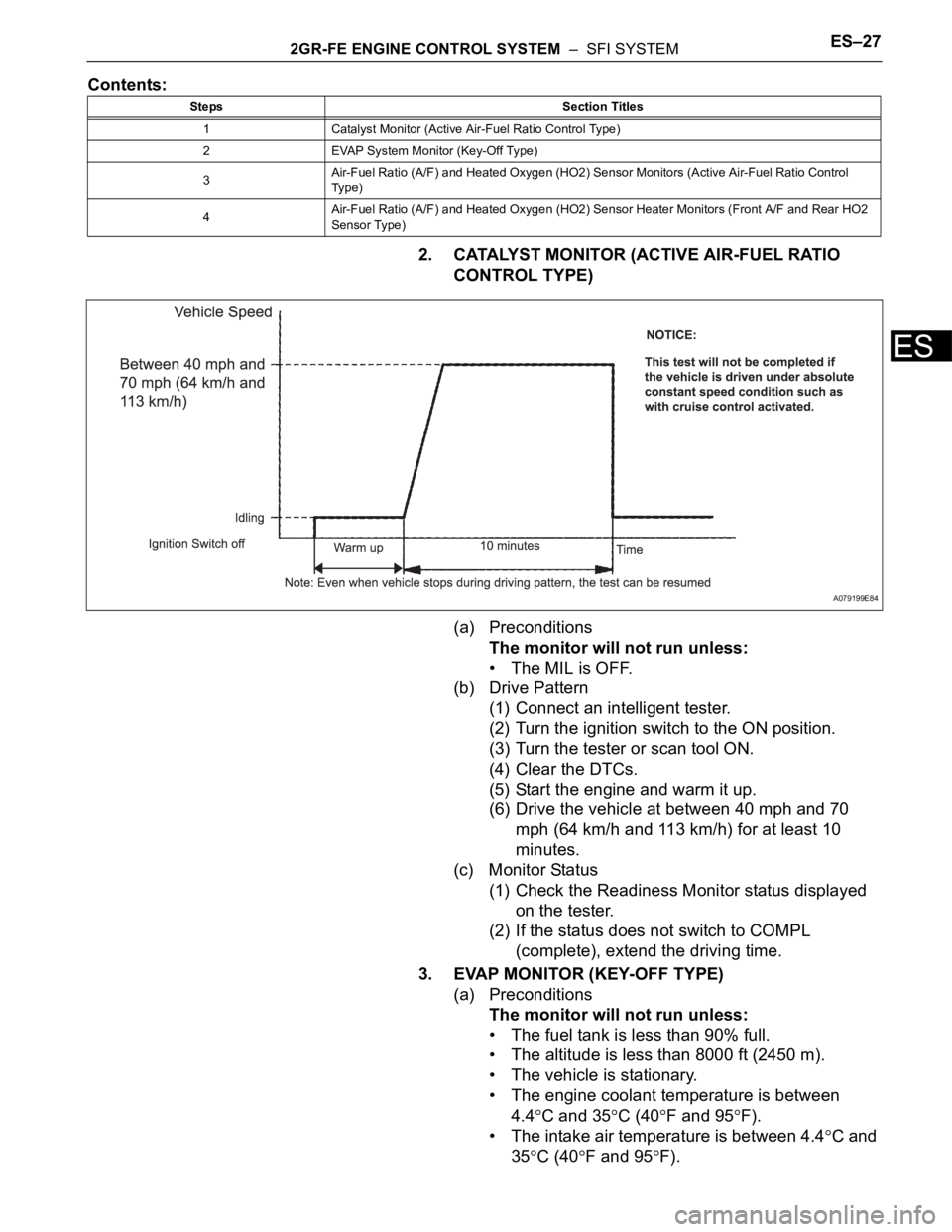
2. CATALYST MONITOR (ACTIVE AIR-FUEL RATIO
CONTROL TYPE)
(a) Preconditions
The monitor will not run unless:
• The MIL is OFF.
(b) Drive Pattern
(1) Connect an intelligent tester.
(2) Turn the ignition switch to the ON position.
(3) Turn the tester or scan tool ON.
(4) Clear the DTCs.
(5) Start the engine and warm it up.
(6) Drive the vehicle at between 40 mph and 70
mph (64 km/h and 113 km/h) for at least 10
minutes.
(c) Monitor Status
(1) Check the Readiness Monitor status displayed
on the tester.
(2) If the status does not switch to COMPL
(complete), extend the driving time.
3. EVAP MONITOR (KEY-OFF TYPE)
(a) Preconditions
The monitor will not run unless:
• The fuel tank is less than 90% full.
• The altitude is less than 8000 ft (2450 m).
• The vehicle is stationary.
• The engine coolant temperature is between
4.4
C and 35C (40F and 95F).
• The intake air temperature is between 4.4
C and
35
C (40F and 95F).
Steps Section Titles
1 Catalyst Monitor (Active Air-Fuel Ratio Control Type)
2 EVAP System Monitor (Key-Off Type)
3Air-Fuel Ratio (A/F) and Heated Oxygen (HO2) Sensor Monitors (Active Air-Fuel Ratio Control
Ty p e )
4Air-Fuel Ratio (A/F) and Heated Oxygen (HO2) Sensor Heater Monitors (Front A/F and Rear HO2
Sensor Type)
A079199E84