Page 414 of 3000
ES–1082GR-FE ENGINE CONTROL SYSTEM – SFI SYSTEM
ES
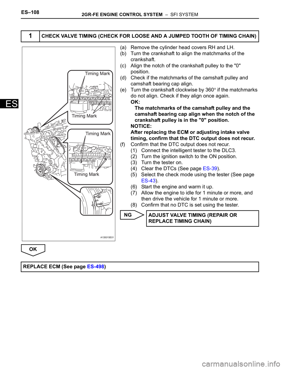
(a) Remove the cylinder head covers RH and LH.
(b) Turn the crankshaft to align the matchmarks of the
crankshaft.
(c) Align the notch of the crankshaft pulley to the "0"
position.
(d) Check if the matchmarks of the camshaft pulley and
camshaft bearing cap align.
(e) Turn the crankshaft clockwise by 360
if the matchmarks
do not align. Check if they align once again.
OK:
The matchmarks of the camshaft pulley and the
camshaft bearing cap align when the notch of the
crankshaft pulley is in the "0" position.
NOTICE:
After replacing the ECM or adjusting intake valve
timing, confirm that the DTC output does not recur.
(f) Confirm that the DTC output does not recur.
(1) Connect the intelligent tester to the DLC3.
(2) Turn the ignition switch to the ON position.
(3) Turn the tester on.
(4) Clear the DTCs (See page ES-39).
(5) Select the check mode using the tester (See page
ES-43).
(6) Start the engine and warm it up.
(7) Allow the engine to idle for 1 minute or more, and
then drive the vehicle for 1 minute or more.
(8) Confirm that no DTC is set using the tester.
NG
OK
1CHECK VALVE TIMING (CHECK FOR LOOSE AND A JUMPED TOOTH OF TIMING CHAIN)
A135015E01
ADJUST VALVE TIMING (REPAIR OR
REPLACE TIMING CHAIN)
REPLACE ECM (See page ES-498)
Page 417 of 3000
2GR-FE ENGINE CONTROL SYSTEM – SFI SYSTEMES–111
ES
P0032 and P0052:
TYPICAL MALFUNCTION THRESHOLDS
P0031 and P0051:
P0032 and P0052:
COMPONENT OPERATING RANGE
MONITOR RESULT
Refer to CHECKING MONITOR STATUS (See page ES-19).
WIRING DIAGRAM
Refer to DTC P2195 (See page ES-359).
INSPECTION PROCEDURE
HINT:
Read freeze frame data using the intelligent tester. The ECM records vehicle and driving condition
information as freeze frame data the moment a DTC is stored. When troubleshooting, freeze frame data
can be helpful in determining whether the vehicle was running or stopped, whether the engine was
warmed up or not, whether the air-fuel ratio was lean or rich, as well as other data recorded at the time of
a malfunction.
Time after engine starts 10 seconds or more
Time after engine starts 10 seconds or more
Heater current Less than 0.8 A
Hybrid IC high current limit port Fail
A/F sensor heater current 0.8 A or more
Page 425 of 3000

2GR-FE ENGINE CONTROL SYSTEM – SFI SYSTEMES–119
ES
TYPICAL ENABLING CONDITIONS
All:
P0037 and P0057:
P0038 and P0058 Case 1:
P0038 and P0058 Case 2:
P0141 and P0161:
TYPICAL MALFUNCTION THRESHOLDS
P0037 and P0057:
P0038 and P0058:
P0141 and P0161 (Heater performance monitor check):
COMPONENT OPERATING RANGE
MONITOR RESULT
Refer to CHECKING MONITOR STATUS (See page ES-19).
WIRING DIAGRAM
Refer to DTC P0136 (See page ES-167).
INSPECTION PROCEDURE
HINT:
• If other DTCs relating to different systems that have terminal E2 as the ground terminal are output
simultaneously, terminal E2 may have an open circuit.
Monitor runs whenever following DTCs are not present None
Battery voltage 10.5 to 20 V
Battery voltage 10.5 V or more
Engine Running
Sta r t e r OF F
Battery voltage 10.5 to 20 V
One of the following conditions is met: Condition A or B
A. All of the following conditions are met: Conditions 1, 2, 3, 4 and 5
1. Battery voltage 10.5 V or more
2. Fuel cut OFF
3. Time after fuel cut ON to OFF 30 seconds or more
4. Accumulated heater ON time 100 seconds or more
5. Learned heater OFF current operation Completed
B. Duration that rear heated oxygen sensor impedance is less than 15
k
2 seconds or more
Heater Current - Learned heater OFF current Less than 0.3 A
Learned heater OFF current More than 2 A
Heater Current - Learned heater OFF current 2 A or more
Accumulated heater resistance Varies with sensor element temperature (Example: More than 23
)
Heated Oxygen (HO2) sensor heater current0.4 to 1 A (when engine idles, HO2 sensor warmed up and battery voltage 11 to 14
V)
Page 426 of 3000
ES–1202GR-FE ENGINE CONTROL SYSTEM – SFI SYSTEM
ES
• Read freeze frame data using the intelligent tester. The ECM records vehicle and driving condition
information as freeze frame data the moment a DTC is stored. When troubleshooting, freeze frame
data can be helpful in determining whether the vehicle was running or stopped, whether the engine
was warmed up or not, whether the air-fuel ratio was lean or rich, as well as other data recorded at the
time of a malfunction.
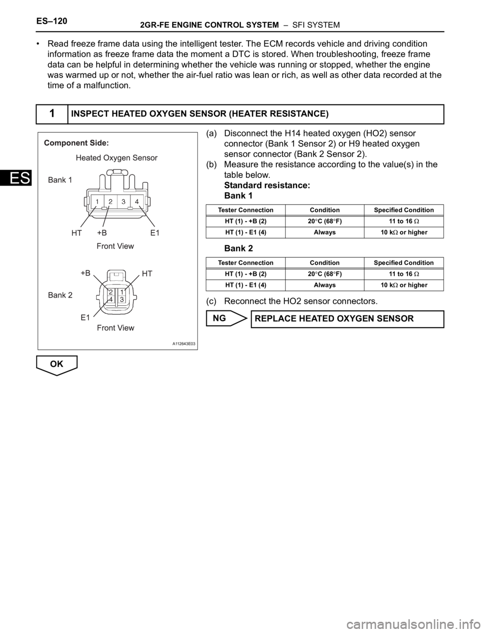
(a) Disconnect the H14 heated oxygen (HO2) sensor
connector (Bank 1 Sensor 2) or H9 heated oxygen
sensor connector (Bank 2 Sensor 2).
(b) Measure the resistance according to the value(s) in the
table below.
Standard resistance:
Bank 1
Bank 2
(c) Reconnect the HO2 sensor connectors.
NG
OK
1INSPECT HEATED OXYGEN SENSOR (HEATER RESISTANCE)
A112643E03
Tester Connection Condition Specified Condition
HT (1) - +B (2) 20
C (68F) 11 to 16
HT (1) - E1 (4) Always 10 k or higher
Tester Connection Condition Specified Condition
HT (1) - +B (2) 20
C (68F) 11 to 16
HT (1) - E1 (4) Always 10 k or higher
REPLACE HEATED OXYGEN SENSOR
Page 432 of 3000
ES–1262GR-FE ENGINE CONTROL SYSTEM – SFI SYSTEM
ES
WIRING DIAGRAM
INSPECTION PROCEDURE
HINT:
Read freeze frame data using the intelligent tester. The ECM records vehicle and driving condition
information as freeze frame data the moment a DTC is stored. When troubleshooting, freeze frame data
can be helpful in determining whether the vehicle was running or stopped, whether the engine was
warmed up or not, whether the air-fuel ratio was lean or rich, as well as other data recorded at the time of
a malfunction.
(a) Connect the intelligent tester to the DLC3.
(b) Start the engine.
(c) Turn the tester on.
(d) Select the following menu items: DIAGNOSIS /
ENHANCED OBD II / DATA LIST / PRIMARY / MAF.
(e) Read the values displayed on the tester.
1READ VALUE OF INTELLIGENT TESTER (MASS AIR FLOW RATE)
A117876E09
Page 437 of 3000
2GR-FE ENGINE CONTROL SYSTEM – SFI SYSTEMES–131
ESTYPICAL MALFUNCTION THRESHOLDS
WIRING DIAGRAM
Refer to DTC P0100 (See page ES-118).
INSPECTION PROCEDURE
HINT:
Read freeze frame data using the intelligent tester. The ECM records vehicle and driving condition
information as freeze frame data the moment a DTC is stored. When troubleshooting, freeze frame data
can be helpful in determining whether the vehicle was running or stopped, whether the engine was
warmed up or not, whether the air-fuel ratio was lean or rich, as well as other data recorded at the time of
a malfunction.
(a) Connect the intelligent tester to the DLC3.
(b) Turn the ignition switch to the ON position.
(c) Turn the tester on.
(d) Select the following menu items: DIAGNOSIS /
ENHANCED OBD II / DTC INFO / CURRENT CODES.
(e) Read the DTCs.
Result
HINT:
If any DTCs other than P0101 are output, troubleshoot
those DTCs first.
B
A
Engine Running
Battery voltage 10.5 V or more
ECT 70
C (158F) or more
IAT sensor current OK
ECT sensor current OK
CKP sensor current OK
TP sensor current OK
FTP sensor OK
EVAP leak detection pump OK
EVAP vent valve OK
Averaged engine load Less than 0.80 %, or more than 1.24 %
1CHECK ANY OTHER DTCS OUTPUT (IN ADDITION TO DTC P0101)
Display (DTC Output) Proceed to
P0101 and other DTCs A
P0101 B
REPLACE MASS AIR FLOW METER (See
page ES-504)
GO TO DTC CHART (See page ES-56)
Page 440 of 3000
ES–1342GR-FE ENGINE CONTROL SYSTEM – SFI SYSTEM
ES
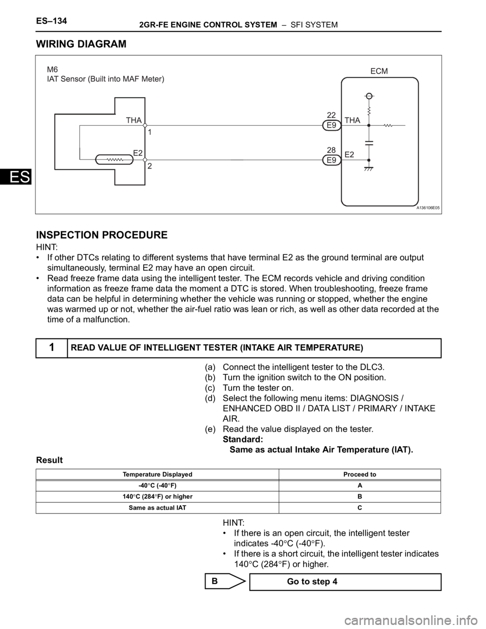
WIRING DIAGRAM
INSPECTION PROCEDURE
HINT:
• If other DTCs relating to different systems that have terminal E2 as the ground terminal are output
simultaneously, terminal E2 may have an open circuit.
• Read freeze frame data using the intelligent tester. The ECM records vehicle and driving condition
information as freeze frame data the moment a DTC is stored. When troubleshooting, freeze frame
data can be helpful in determining whether the vehicle was running or stopped, whether the engine
was warmed up or not, whether the air-fuel ratio was lean or rich, as well as other data recorded at the
time of a malfunction.
(a) Connect the intelligent tester to the DLC3.
(b) Turn the ignition switch to the ON position.
(c) Turn the tester on.
(d) Select the following menu items: DIAGNOSIS /
ENHANCED OBD II / DATA LIST / PRIMARY / INTAKE
AIR.
(e) Read the value displayed on the tester.
Standard:
Same as actual Intake Air Temperature (IAT).
Result
HINT:
• If there is an open circuit, the intelligent tester
indicates -40
C (-40F).
• If there is a short circuit, the intelligent tester indicates
140
C (284F) or higher.
B
1READ VALUE OF INTELLIGENT TESTER (INTAKE AIR TEMPERATURE)
A136106E05
Temperature Displayed Proceed to
-40
C (-40F) A
140
C (284F) or higher B
Same as actual IAT C
Go to step 4
Page 444 of 3000
ES–1382GR-FE ENGINE CONTROL SYSTEM – SFI SYSTEM
ES
DESCRIPTION
The Intake Air Temperature (IAT) sensor, mounted on the Mass Air Flow (MAF) meter, monitors the IAT.
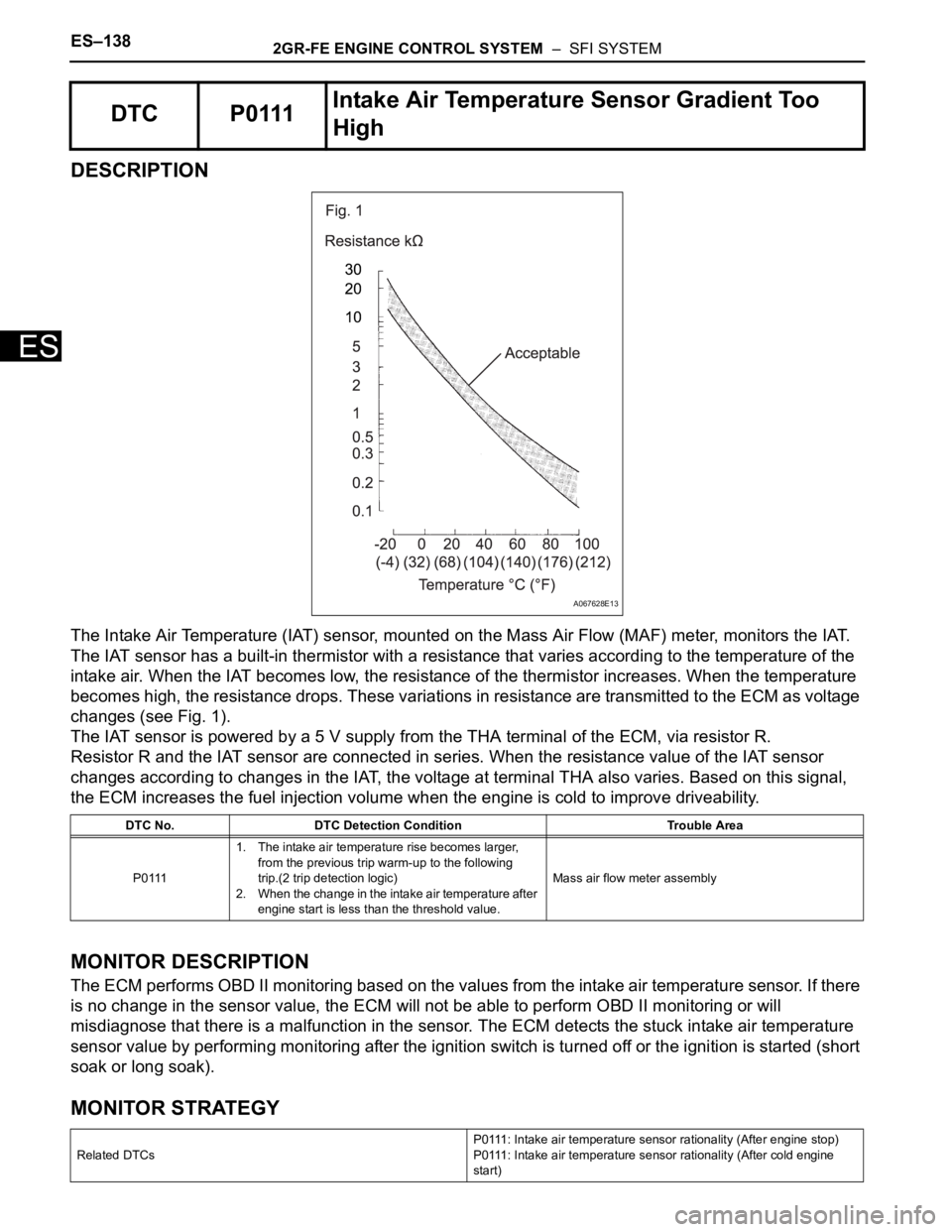
The IAT sensor has a built-in thermistor with a resistance that varies according to the temperature of the
intake air. When the IAT becomes low, the resistance of the thermistor increases. When the temperature
becomes high, the resistance drops. These variations in resistance are transmitted to the ECM as voltage
changes (see Fig. 1).
The IAT sensor is powered by a 5 V supply from the THA terminal of the ECM, via resistor R.
Resistor R and the IAT sensor are connected in series. When the resistance value of the IAT sensor
changes according to changes in the IAT, the voltage at terminal THA also varies. Based on this signal,
the ECM increases the fuel injection volume when the engine is cold to improve driveability.
MONITOR DESCRIPTION
The ECM performs OBD II monitoring based on the values from the intake air temperature sensor. If there
is no change in the sensor value, the ECM will not be able to perform OBD II monitoring or will
misdiagnose that there is a malfunction in the sensor. The ECM detects the stuck intake air temperature
sensor value by performing monitoring after the ignition switch is turned off or the ignition is started (short
soak or long soak).
MONITOR STRATEGY
DTC P0111Intake Air Temperature Sensor Gradient Too
High
DTC No. DTC Detection Condition Trouble Area
P01111. The intake air temperature rise becomes larger,
from the previous trip warm-up to the following
trip.(2 trip detection logic)
2. When the change in the intake air temperature after
engine start is less than the threshold value.Mass air flow meter assembly
Related DTCsP0111: Intake air temperature sensor rationality (After engine stop)
P0111: Intake air temperature sensor rationality (After cold engine
start)
A067628E13