2007 TOYOTA SIENNA control arm
[x] Cancel search: control armPage 354 of 3000

ES–282GR-FE ENGINE CONTROL SYSTEM – SFI SYSTEM
ES
• Vehicle was driven in the city area (or on free-
way) for 10 minutes or more.
(b) Monitor Conditions
(1) Turn the ignition switch off and wait for 6 hours.
HINT:
Do not start the engine until checking Readiness
Monitor status. If the engine is started, the step
described above must be repeated.
(c) Monitor Status
(1) Connect an intelligent tester to the DLC3.
(2) Turn the ignition switch to the ON position.
(3) Turn the tester or scan tool ON.
(4) Check the Readiness Monitor status displayed
on the tester or scan tool.
If the status does not switch to COMPL
(complete), restart the engine, make sure that
the preconditions have been met, and then
perform the Monitor Conditions again.
4. A/F SENSOR AND HO2S MONITORS
(a) Preconditions
The monitor will not run unless:
• 2 minutes or more have elapsed since the engine
was started.
• The Engine Coolant Temperature (ECT) is 75
C
(167
F) or more.
• Cumulative driving time at a vehicle speed of 30
mph (48 km/h) or more exceeds 6 minutes.
• Air-fuel ratio feedback control is performed.
• Fuel-cut control is performed for 8 seconds or
more (for the Rear HO2 Sensor Monitor).
(b) Drive Pattern for front A/F sensor and HO2 sensor.
(1) Connect an intelligent tester to the DLC3.
(2) Turn the ignition switch to the ON position.
(3) Turn the tester ON.
(4) Clear the DTCs.
(5) Start the engine, and warm it up until the ECT
reaches 75
C (167F) or higher.
(6) Drive the vehicle at 38 mph (60 km/h) or more
for at least 10 minutes.
(7) Change the transmission to the 2nd gear.
(8) Accelerate the vehicle to 40 mph (64 km/h) or
more by depressing the accelerator pedal for at
least 10 seconds (Procedure "A").
(9) Soon after performing procedure "A" above,
release the accelerator pedal for at least 4
seconds without depressing the brake pedal, in
order to execute fuel-cut control (Procedure "B").
(10) Allow the vehicle to decelerate until the vehicle
speed declines to less than 6 mph (10 km/h)
(Procedure "C").
(11) Repeat procedures from "A" through "C" above
at least 3 times in one driving cycle.
Page 360 of 3000
ES–422GR-FE ENGINE CONTROL SYSTEM – SFI SYSTEM
ES
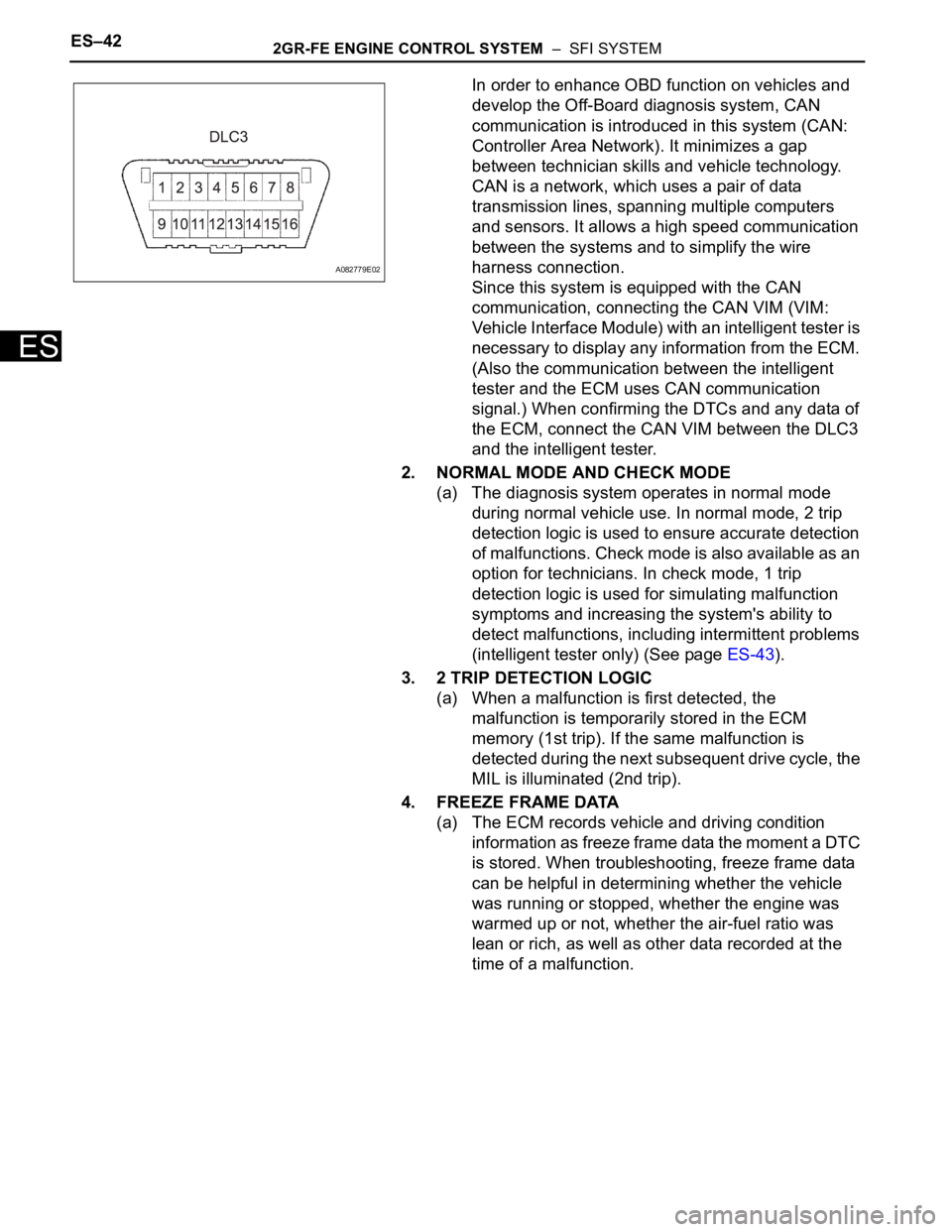
In order to enhance OBD function on vehicles and
develop the Off-Board diagnosis system, CAN
communication is introduced in this system (CAN:
Controller Area Network). It minimizes a gap
between technician skills and vehicle technology.
CAN is a network, which uses a pair of data
transmission lines, spanning multiple computers
and sensors. It allows a high speed communication
between the systems and to simplify the wire
harness connection.
Since this system is equipped with the CAN
communication, connecting the CAN VIM (VIM:
Vehicle Interface Module) with an intelligent tester is
necessary to display any information from the ECM.
(Also the communication between the intelligent
tester and the ECM uses CAN communication
signal.) When confirming the DTCs and any data of
the ECM, connect the CAN VIM between the DLC3
and the intelligent tester.
2. NORMAL MODE AND CHECK MODE
(a) The diagnosis system operates in normal mode
during normal vehicle use. In normal mode, 2 trip
detection logic is used to ensure accurate detection
of malfunctions. Check mode is also available as an
option for technicians. In check mode, 1 trip
detection logic is used for simulating malfunction
symptoms and increasing the system's ability to
detect malfunctions, including intermittent problems
(intelligent tester only) (See page ES-43).
3. 2 TRIP DETECTION LOGIC
(a) When a malfunction is first detected, the
malfunction is temporarily stored in the ECM
memory (1st trip). If the same malfunction is
detected during the next subsequent drive cycle, the
MIL is illuminated (2nd trip).
4. FREEZE FRAME DATA
(a) The ECM records vehicle and driving condition
information as freeze frame data the moment a DTC
is stored. When troubleshooting, freeze frame data
can be helpful in determining whether the vehicle
was running or stopped, whether the engine was
warmed up or not, whether the air-fuel ratio was
lean or rich, as well as other data recorded at the
time of a malfunction.
A082779E02
Page 364 of 3000
ES–462GR-FE ENGINE CONTROL SYSTEM – SFI SYSTEM
ES
FREEZE FRAME DATA
1. DESCRIPTION
(a) The ECM records vehicle and driving condition
information as freeze frame data the moment a DTC
is stored. When troubleshooting, freeze frame data
can be helpful in determining whether the vehicle
was running or stopped, whether the engine was
warmed up or not, whether the air-fuel ratio was
lean or rich, as well as other data recorded at the
time of a malfunction.
HINT:
If it is impossible to duplicate the problem even
though a DTC is detected, confirm the freeze frame
data.
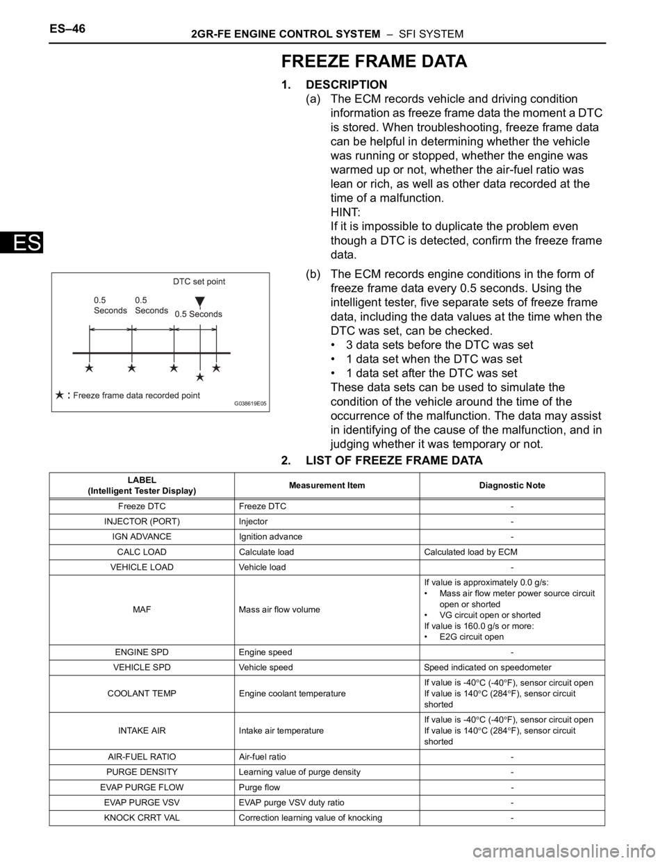
(b) The ECM records engine conditions in the form of
freeze frame data every 0.5 seconds. Using the
intelligent tester, five separate sets of freeze frame
data, including the data values at the time when the
DTC was set, can be checked.
• 3 data sets before the DTC was set
• 1 data set when the DTC was set
• 1 data set after the DTC was set
These data sets can be used to simulate the
condition of the vehicle around the time of the
occurrence of the malfunction. The data may assist
in identifying of the cause of the malfunction, and in
judging whether it was temporary or not.
2. LIST OF FREEZE FRAME DATA
G038619E05
LABEL
(Intelligent Tester Display)Measurement Item Diagnostic Note
Freeze DTC Freeze DTC -
INJECTOR (PORT) Injector -
IGN ADVANCE Ignition advance -
CALC LOAD Calculate load Calculated load by ECM
VEHICLE LOAD Vehicle load -
MAF Mass air flow volumeIf value is approximately 0.0 g/s:
• Mass air flow meter power source circuit
open or shorted
• VG circuit open or shorted
If value is 160.0 g/s or more:
• E2G circuit open
ENGINE SPD Engine speed -
VEHICLE SPD Vehicle speed Speed indicated on speedometer
COOLANT TEMP Engine coolant temperatureIf value is -40
C (-40F), sensor circuit open
If value is 140
C (284F), sensor circuit
shorted
INTAKE AIR Intake air temperatureIf value is -40
C (-40F), sensor circuit open
If value is 140C (284F), sensor circuit
shorted
AIR-FUEL RATIO Air-fuel ratio -
PURGE DENSITY Learning value of purge density -
EVAP PURGE FLOW Purge flow -
EVAP PURGE VSV EVAP purge VSV duty ratio -
KNOCK CRRT VAL Correction learning value of knocking -
Page 367 of 3000

2GR-FE ENGINE CONTROL SYSTEM – SFI SYSTEMES–49
ES
FC IDL Idle fuel cutON: when throttle valve fully closed and
engine speed over 1500 rpm
FC TAU FC TAUFuel cut initiated under light load to prevent
incomplete combustion
IGNITION Ignition -
CYL #1 Cylinder #1 misfire rate Displayed only during idling
CYL #2 Cylinder #2 misfire rate Displayed only during idling
CYL #3 Cylinder #3 misfire rate Displayed only during idling
CYL #4 Cylinder #4 misfire rate Displayed only during idling
CYL #5 Cylinder #5 misfire rate Displayed only during idling
CYL #6 Cylinder #6 misfire rate Displayed only during idling
CYL ALL All cylinder misfire rate Displayed only during idling
MISFIRE RPM Misfire RPM -
MISFIRE LOAD Misfire load -
MISFIRE MARGIN Misfire monitoring -
ENG RUN TIME Accumulated engine running time -
TIME DTC CLEAR Cumulative time after DTC cleared -
DIST DTC CLEAR Accumulated distance after DTC cleared -
WU CYC DTC CLEAR Warm-up cycle after DTC cleared -LABEL
(Intelligent Tester Display)Measurement Item Diagnostic Note
Page 391 of 3000
2GR-FE ENGINE CONTROL SYSTEM – SFI SYSTEMES–85
ES
WIRING DIAGRAM
INSPECTION PROCEDURE
HINT:
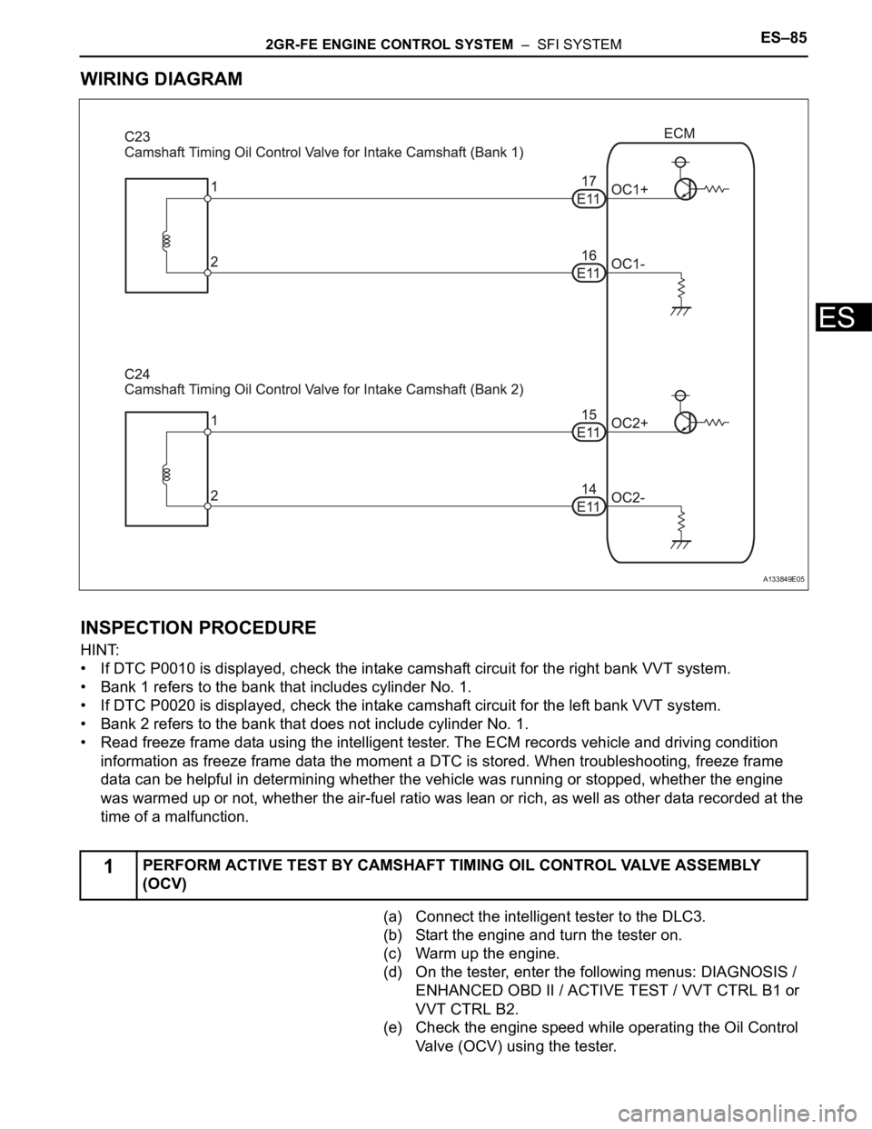
• If DTC P0010 is displayed, check the intake camshaft circuit for the right bank VVT system.
• Bank 1 refers to the bank that includes cylinder No. 1.
• If DTC P0020 is displayed, check the intake camshaft circuit for the left bank VVT system.
• Bank 2 refers to the bank that does not include cylinder No. 1.
• Read freeze frame data using the intelligent tester. The ECM records vehicle and driving condition
information as freeze frame data the moment a DTC is stored. When troubleshooting, freeze frame
data can be helpful in determining whether the vehicle was running or stopped, whether the engine
was warmed up or not, whether the air-fuel ratio was lean or rich, as well as other data recorded at the
time of a malfunction.
(a) Connect the intelligent tester to the DLC3.
(b) Start the engine and turn the tester on.
(c) Warm up the engine.
(d) On the tester, enter the following menus: DIAGNOSIS /
ENHANCED OBD II / ACTIVE TEST / VVT CTRL B1 or
VVT CTRL B2.
(e) Check the engine speed while operating the Oil Control
Valve (OCV) using the tester.
1PERFORM ACTIVE TEST BY CAMSHAFT TIMING OIL CONTROL VALVE ASSEMBLY
(OCV)
A133849E05
Page 394 of 3000

ES–882GR-FE ENGINE CONTROL SYSTEM – SFI SYSTEM
ES
HINT:
If DTC P0011, P0012, P0021 or P0022 is present, check the VVT (Variable Valve Timing) system.
DESCRIPTION
Refer to DTC P0010 (See page ES-75).
MONITOR DESCRIPTION
The ECM optimizes the intake valve timing using the VVT (Variable Valve Timing) system to control the
intake camshaft. The VVT system includes the ECM, the Oil Control Valve (OCV) and the VVT controller.
The ECM sends a target duty-cycle control signal to the OCV. This control signal regulates the oil
pressure applied to the VVT controller. The VVT controller can advance or retard the intake camshaft.
If the difference between the target and actual intake valve timings is large, and changes in actual intake
valve timing are small, the ECM interprets this as the VVT controller stuck malfunction and sets a DTC.
Example:
A DTC will be set when the following conditions 1), 2) and 3) are met:
1) The difference between the target and actual intake valve timings is more than 5
CA (Crankshaft
Angle) and the condition continues for more than 4.5 seconds.
2) It takes 5 seconds or more to change the valve timing by 5
CA.
DTC P0011Camshaft Position "A" - Timing Over-Advanced
or System Performance (Bank 1)
DTC P0012Camshaft Position "A" - Timing Over-Retarded
(Bank 1)
DTC P0021Camshaft Position "A" - Timing Over-Advanced
or System Performance (Bank 2)
DTC P0022Camshaft Position "A" - Timing Over-Retarded
(Bank 2)
DTC No. DTC Detection Condition Trouble Area
P0011
P0021Advanced cam timing:
With warm engine and engine speed of between 500
rpm and 4000 rpm, all conditions (a), (b) and (c) are
met (1 trip detection logic):
(a) Difference between target and actual intake valve
timings is more than 5
CA (Crankshaft Angle) for 4.5
seconds
(b) Current intake valve timing is fixed (timing changes
less than 5
CA in 5 seconds)
(c) Variations in VVT controller timing are more than 19
CA of maximum delayed timing (advanced)• Valve timing
• OCV for intake camshaft
• OCV filter
• Intake camshaft (bank 1) timing gear assembly
•ECM
P0012
P0022Retarded cam timing:
With warm engine and engine speed of between 500
rpm and 4000 rpm, all conditions (a), (b) and (c) are
met (2 trip detection logic):
(a) Difference between target and actual intake valve
timings is more than 5
CA (Crankshaft Angle) for 4.5
seconds
(b) Current intake valve timing is fixed (timing changes
less than 5
CA in 5 seconds)
(c) Variations in VVT controller timing is 19
CA or less
of maximum delayed timing (retarded)• Valve timing
• OCV for intake camshaft
• OCV filter
• Intake camshaft (bank 2) timing gear assembly
•ECM
Page 395 of 3000

2GR-FE ENGINE CONTROL SYSTEM – SFI SYSTEMES–89
ES
3) After above conditions 1) and 2) are met, the OCV is forcibly activated 63 times or more.
DTCs P0011 and P0021 (Advanced Cam Timing) are detected with 1 trip detection logic.
DTCs P0012 and P0022 (Retarded Cam Timing) are detected with 2 trip detection logic.
These DTCs indicate that the VVT controller cannot operate properly due to OCV malfunctions or the
presence of foreign objects in the OCV.
The monitor will not run unless the following conditions are met:
- The engine is warm (the engine coolant temperature is 75
C [167F] or more).
- The vehicle has been driven at more than 40 mph (64 km/h) for 3 minutes.
- The engine has idled for 3 minutes.
MONITOR STRATEGY
TYPICAL ENABLING CONDITIONS
TYPICAL MALFUNCTION THRESHOLDS
P0011, P0021:
P0012, P0022:
If the difference between the target and actual camshaft timings is greater than the specified value, the
ECM operates the VVT actuator.
Then, the ECM monitors the camshaft timing change for 5 seconds.
WIRING DIAGRAM
Refer to DTC P0010 (See page ES-77).
INSPECTION PROCEDURE
Related DTCsP0011: Advanced intake camshaft timing (bank 1)
P0012: Retarded intake camshaft timing (bank 1)
P0021: Advanced intake camshaft timing (bank 2)
P0022: Retarded intake camshaft timing (bank 2)
Required sensors / components (Main) VVT OCV, VVT Actuator
Required sensors / components (Related) Crankshaft position sensor, Camshaft position sensor, ECT sensor
Frequency of operation Once per driving cycles
Duration Less than 10 seconds
MIL operationP0011 and P0021: Immediate
P0012 and P0022: 2 driving cycles
Sequence operation None
The monitor will run whenever these DTCs are not
presentP0100, P0101, P0102, P0103 (MAF Sensor), P0115, P0116, P0117, P0118 (ECT
Sensor), P0125 (Insufficient ECT for Closed Loop), P0335 (CKP Sensor), P0340
(CMP Sensor), P0351, P0352, P0353, P0354, P0355, P0356 (Ignitor)
Battery voltage 11 V or more
Engine RPM 500 to 4000 rpm
ECT 75 to 100
C (167 to 212F)
Duration of actual valve timing and target valve timing More than 5
CA (Crankshaft angle)
Valve timing No change in advanced valve timing
Duration of actual valve timing and target valve timing More than 5
CA (Crankshaft angle)
Valve timing No change in retarded valve timing
Abnormal bankAdvanced timing over
(Valve timing is out of specified range)Retarded timing over
(Valve timing is out of specified range)
Bank 1 P0011 P0012
Bank 2 P0021 P0022
Page 396 of 3000

ES–902GR-FE ENGINE CONTROL SYSTEM – SFI SYSTEM
ES
HINT:
• If DTC P0011 or P0012 is displayed, check the bank 1 VVT system circuit.
• Bank 1 refers to the bank that includes cylinder No. 1.
• If DTC P0021 or P0022 is displayed, check the bank 2 VVT system circuit.
• Bank 2 refers to the bank that does not include cylinder No. 1.
• Read freeze frame data using the intelligent tester. The ECM records vehicle and driving condition
information as freeze frame data the moment a DTC is stored. When troubleshooting, freeze frame
data can be helpful in determining whether the vehicle was running or stopped, whether the engine
was warmed up or not, whether the air-fuel ratio was lean or rich, as well as other data recorded at the
time of a malfunction.
(a) Connect the intelligent tester to the DLC3.
(b) Turn the ignition switch to the ON position and turn the
tester on.
(c) Select the following menu items: DIAGNOSIS /
ENHANCED OBD II / DTC INFO / CURRENT CODES.
(d) Read the DTCs.
Result
HINT:
If any DTCs other than P0011, P0012, P0021 or P0022
are output, troubleshoot those DTCs first.
B
A
(a) Connect the intelligent tester to the DLC3.
(b) Start the engine and turn the tester on.
(c) Warm up the engine.
(d) Select the following menu items on the tester:
DIAGNOSIS / ENHANCED OBD II / ACTIVE TEST /
VVT CTRL B1.
(e) Check the engine speed while operating the Oil Control
Valve (OCV) using the tester.
OK
NG
OK
1CHECK ANY OTHER DTCS OUTPUT (IN ADDITION TO DTC P0011, P0012, P0021 OR
P0022)
Display (DTC Output) Proceed to
P0011, P0012, P0021 or P0022 A
P0011, P0012, P0021 or P0022 and other DTCs B
GO TO DTC CHART (See page ES-56)
2PERFORM ACTIVE TEST BY INTELLIGENT TESTER (OPERATE OCV)
Tester Operation Specified Condition
OCV OFF Normal engine idle speed
OCV ON Engine idles roughly or stalls (soon after OCV switched from OFF to ON)
Go to step 4