Page 4403 of 5883
MWI-96
< ON-VEHICLE REPAIR >
COMBINATION METER
17. Remove screws (A) and metal clip (B), and remove combination
meter.
Installation
Installation is in the reverse order of removal.
PKIC0703E
Page 4404 of 5883
MWI
COMBINATION METER
MWI-97
< DISASSEMBLY AND ASSEMBLY >
C
D
E
F
G
H
I
J
K
L
MB A
O
P
DISASSEMBLY AND ASSEMBLY
COMBINATION METER
Disassembly and AssemblyINFOID:0000000001716785
COMBINATION METER
Disassembly
1. Remove the combination meter. Refer to MWI-94, "Removal and Installation".
2. Disengage the eight tabs to separate front cover (1) from the
unified meter control unit assembly (2).
Assembly
Assembly is in the reverse order of disassembly.
LIIA2582E
Page 4410 of 5883
PB-6
< REMOVAL AND INSTALLATION >
PARKING BRAKE CONTROL
6. Remove device assembly mounting nuts, and remove device assembly from vehicle.
7. Remove rear disc rotor and remove rear cable from the operating lever. Refer to PB-7, "
Removal and
Installation" .
8. Remove the exhaust center tube and heat plate. Refer to EX-5, "
Removal and Installation" (HR16DE),
EX-10, "
Removal and Installation" (MR18DE), EX-14, "Removal and Installation" (K9K).
9. Remove rear cable mounting bolt and nut, and then remove rear cable from the vehicle.
10. Remove adjusting nut and front cable from device assembly.
INSTALLATION
1. Installation is in the reverse order of the removal. Tighten mounting bolts and nuts to the specified torque.
2. Adjust clearance of parking brake shoes. Refer to PB-4, "
On-Vehicle Service" .
Page 4412 of 5883

PB-8
< REMOVAL AND INSTALLATION >
PARKING BRAKE SHOE
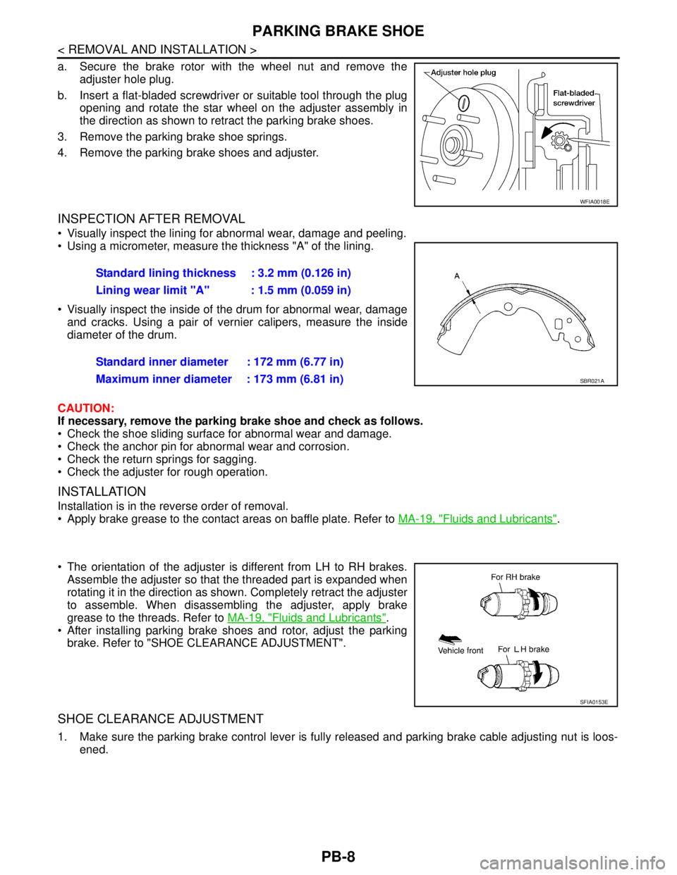
a. Secure the brake rotor with the wheel nut and remove the
adjuster hole plug.
b. Insert a flat-bladed screwdriver or suitable tool through the plug
opening and rotate the star wheel on the adjuster assembly in
the direction as shown to retract the parking brake shoes.
3. Remove the parking brake shoe springs.
4. Remove the parking brake shoes and adjuster.
INSPECTION AFTER REMOVAL
Visually inspect the lining for abnormal wear, damage and peeling.
Using a micrometer, measure the thickness "A" of the lining.
Visually inspect the inside of the drum for abnormal wear, damage
and cracks. Using a pair of vernier calipers, measure the inside
diameter of the drum.
CAUTION:
If necessary, remove the parking brake shoe and check as follows.
Check the shoe sliding surface for abnormal wear and damage.
Check the anchor pin for abnormal wear and corrosion.
Check the return springs for sagging.
Check the adjuster for rough operation.
INSTALLATION
Installation is in the reverse order of removal.
Apply brake grease to the contact areas on baffle plate. Refer to MA-19, "
Fluids and Lubricants".
The orientation of the adjuster is different from LH to RH brakes.
Assemble the adjuster so that the threaded part is expanded when
rotating it in the direction as shown. Completely retract the adjuster
to assemble. When disassembling the adjuster, apply brake
grease to the threads. Refer to MA-19, "
Fluids and Lubricants".
After installing parking brake shoes and rotor, adjust the parking
brake. Refer to "SHOE CLEARANCE ADJUSTMENT".
SHOE CLEARANCE ADJUSTMENT
1. Make sure the parking brake control lever is fully released and parking brake cable adjusting nut is loos-
ened.
WFIA0018E
Standard lining thickness : 3.2 mm (0.126 in)
Lining wear limit "A" : 1.5 mm (0.059 in)
Standard inner diameter : 172 mm (6.77 in)
Maximum inner diameter : 173 mm (6.81 in)
SBR021A
SFIA0153E
Page 4444 of 5883
PCS-30
< REMOVAL AND INSTALLATION >[IPDM E/R]
IPDM E/R (INTELLIGENT POWER DISTRIBUTION MODULE ENGINE ROOM)
REMOVAL AND INSTALLATION
IPDM E/R (INTELLIGENT POWER DISTRIBUTION MODULE ENGINE
ROOM)
Removal and Installation of IPDM E/RINFOID:0000000001697602
REMOVAL
1. Disconnect negative battery cable.
2. Remove IPDM E/R upper cover.
3. Release 2 clips and pull IPDM E/R up from case.
4. Disconnect IPDM E/R connectors and remove the IPDM E/R.
INSTALLATION
Installation is in the reverse order of removal.
WKIA1454E
WKIA1696E
Page 4461 of 5883
PG-6
< ON-VEHICLE REPAIR >
BATTERY
ON-VEHICLE REPAIR
BATTERY
Removal and InstallationINFOID:0000000001691346
REMOVAL
1. Disconnect battery negative (1) and positive (2) cables from bat-
tery terminals.
CAUTION:
When disconnecting, disconnect the battery cable from the
negative terminal first.
2. Remove battery hold-down wedge nut (A) to remove battery
wedge bracket (3).
3. Remove battery.
INSTALLATION
Installation is in the reverse order of removal.
CAUTION:
When connecting, connect the battery cable to the positive terminal first.
AWMIA0053ZZ
Battery wedge bracket nut : 30 N·m (3.1 kg-m, 22 ft-lb)
Battery terminal nut : 5.4 N·m (0.55 kg-m, 48 in-lb)
Page 4527 of 5883
PWO-4
< ON-VEHICLE REPAIR >
POWER SOCKET
ON-VEHICLE REPAIR
POWER SOCKET
Removal and InstallationINFOID:0000000001728325
REMOVAL
1. Remove the console mask. Refer to IP-11, "Removal and Installation".
2. Remove the power socket (2) from the power socket ring (3),
while pressing the hook (A) on the ring out from square hole (B).
Console mask (1)
Power socket cutout (C)
INSTALLATION
Installation is in the reverse order of removal.
NOTE:
Install the power socket with its cutout aligned with the power socket ring.
SKIB5671E
Page 4533 of 5883

RAX-6
< ON-VEHICLE REPAIR >
WHEEL HUB
ON-VEHICLE REPAIR
WHEEL HUB
Removal and InstallationINFOID:0000000001724589
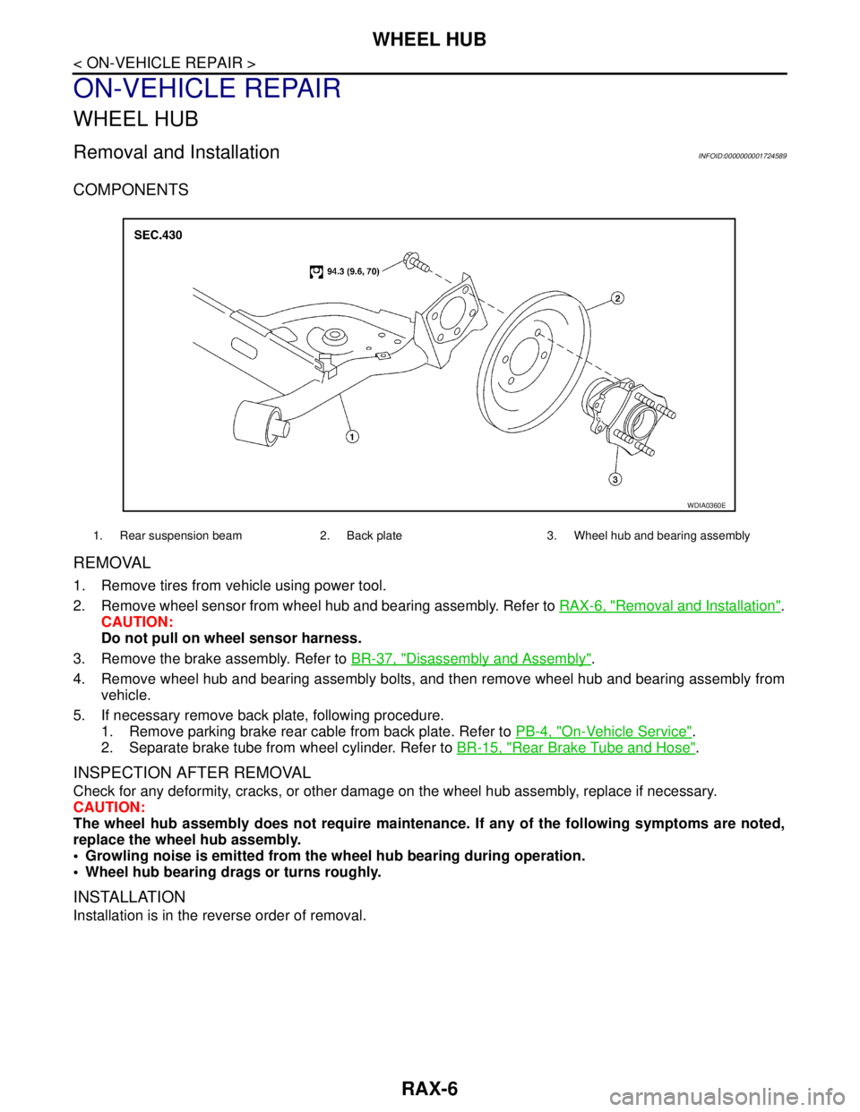
COMPONENTS
REMOVAL
1. Remove tires from vehicle using power tool.
2. Remove wheel sensor from wheel hub and bearing assembly. Refer to RAX-6, "
Removal and Installation".
CAUTION:
Do not pull on wheel sensor harness.
3. Remove the brake assembly. Refer to BR-37, "
Disassembly and Assembly".
4. Remove wheel hub and bearing assembly bolts, and then remove wheel hub and bearing assembly from
vehicle.
5. If necessary remove back plate, following procedure.
1. Remove parking brake rear cable from back plate. Refer to PB-4, "
On-Vehicle Service".
2. Separate brake tube from wheel cylinder. Refer to BR-15, "
Rear Brake Tube and Hose".
INSPECTION AFTER REMOVAL
Check for any deformity, cracks, or other damage on the wheel hub assembly, replace if necessary.
CAUTION:
The wheel hub assembly does not require maintenance. If any of the following symptoms are noted,
replace the wheel hub assembly.
Growling noise is emitted from the wheel hub bearing during operation.
Wheel hub bearing drags or turns roughly.
INSTALLATION
Installation is in the reverse order of removal.
1. Rear suspension beam 2. Back plate 3. Wheel hub and bearing assembly
WDIA0360E