Page 5866 of 5883
WW-64
< ON-VEHICLE REPAIR >
WASHER TANK
WASHER TANK
Removal and InstallationINFOID:0000000001366653
REMOVAL
1. Remove the upper radiator cover. Refer to EXT-19, "Removal and Installation".
2. Remove the clip (A), then pull the washer tank inlet (1) out of the
washer tank.
:Front
3. Remove the front bumper fascia. Refer to EXT-13, "
Removal and Installation".
4. Disconnect the washer pump connector (1).
5. Disconnect the washer tube (2) from the washer pump.
6. Disconnect the headlamp washer pump connector (3).
7. Remove the washer tank bolts (A).
8. Remove the washer tank (4).
INSTALLATION
Installation is in the reverse order of removal.
Add the specified washer fluid up to the top of the washer tank inlet after installation. Check that there are no
leaks.
SKIB5667E
ALLIA0275ZZ
Page 5867 of 5883
WASHER PUMP
WW-65
< ON-VEHICLE REPAIR >
C
D
E
F
G
H
I
J
K
MA
B
WW
N
O
P
WASHER PUMP
Removal and InstallationINFOID:0000000001366655
REMOVAL
1. Remove the front bumper fascia. Refer to EXT-13, "Removal and Installation".
2. Disconnect the washer pump connector (A).
3. Disconnect the washer tube (2) from the washer pump.
4. Remove the washer pump (1) from the washer tank.
INSTALLATION
Installation is in the reverse order of removal.
Add the specified washer fluid up to the top of the washer tank inlet after installation. Check that there are no
leaks.
CAUTION:
Never twist the grommet when installing the washer pump.
ALLIA0276ZZ
Page 5868 of 5883
WW-66
< ON-VEHICLE REPAIR >
HEADLAMP WASHER PUMP
HEADLAMP WASHER PUMP
Removal and InstallationINFOID:0000000001366657
REMOVAL
1. Remove the front bumper fascia. Refer to EXT-13, "Removal and Installation".
2. Disconnect the headlamp washer pump connector (A).
3. Disconnect the headlamp washer pump hose (2) from the head-
lamp washer pump.
4. Remove the headlamp washer pump (1).
INSTALLATION
Installation is in the reverse order of removal.
Add the specified washer fluid up to the top of the washer tank inlet after installation. Check that there are no
leaks.
CAUTION:
Never twist the grommet when installing the washer pump.
ALLIA0277ZZ
Page 5869 of 5883

FRONT WASHER NOZZLE AND TUBE
WW-67
< ON-VEHICLE REPAIR >
C
D
E
F
G
H
I
J
K
MA
B
WW
N
O
P
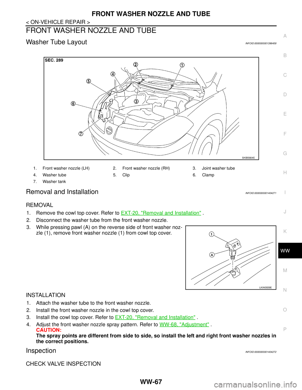
FRONT WASHER NOZZLE AND TUBE
Washer Tube LayoutINFOID:0000000001396458
Removal and InstallationINFOID:0000000001404271
REMOVAL
1. Remove the cowl top cover. Refer to EXT-20, "Removal and Installation" .
2. Disconnect the washer tube from the front washer nozzle.
3. While pressing pawl (A) on the reverse side of front washer noz-
zle (1), remove front washer nozzle (1) from cowl top cover.
INSTALLATION
1. Attach the washer tube to the front washer nozzle.
2. Install the front washer nozzle in the cowl top cover.
3. Install the cowl top cover. Refer to EXT-20, "
Removal and Installation" .
4. Adjust the front washer nozzle spray pattern. Refer to WW-68, "
Adjustment" .
CAUTION:
The spray points are different from side to side, so install the left and right front washer nozzles in
the correct positions.
InspectionINFOID:0000000001404272
CHECK VALVE INSPECTION
1. Front washer nozzle (LH) 2. Front washer nozzle (RH) 3. Joint washer tube
4. Washer tube 5. Clip 6. Clamp
7. Washer tank
SKIB5664E
LKIA0939E
Page 5870 of 5883
WW-68
< ON-VEHICLE REPAIR >
FRONT WASHER NOZZLE AND TUBE
Blow air in the injection direction, and make sure that air flows only
one way. Make sure that the reverse direction is not possible.
AdjustmentINFOID:0000000001404273
Adjust spray positions to match the positions as shown.
Insert a suitable tool into the nozzle hole and move up/down and left/right to adjust to the specified spray
position.
SKIB5665E
1. Windshield A. 395 mm (15.55 in) B. 216 mm (8.50 in)
C. 100 mm (3.94 in) D. 85 mm (3.35 in) E. Black mask
F. 303 mm (11.93 in) G. 212 mm (8.35 in) H. 249 mm (9.80 in)
I. Center of windsheild J. Spray pattern area K. 286 mm (11.26 in)
LKIA0938E
Page 5878 of 5883
WW-76
< ON-VEHICLE REPAIR >
WIPER AND WASHER SWITCH
WIPER AND WASHER SWITCH
Exploded ViewINFOID:0000000001366672
NOTE:
The LHD model shown, RHD model similar.
Removal and InstallationINFOID:0000000001366673
REMOVAL
1. Remove the steering column cover. Refer to IP-10, "Component Parts".
2. While pressing in on the pawls, pull the wiper and washer switch straight out to disconnect it from the
switch base.
INSTALLATION
Installation is in the reverse order of removal.
1. Wiper & washer switch A. Pawl
JPLIA0311ZZ
Page 5880 of 5883
WW-78
< ON-VEHICLE REPAIR >
REAR WIPER MOTOR
2. Clean pivot area as shown. This will reduce the possibility of
wiper arm looseness.
3. Install wiper blade.
4. Install wiper arm so that the arm rests in the stopper and tighten
rear wiper arm nut.
5. Install wiper arm cover.
REAR WIPER MOTOR
Removal
1. Remove wiper arm. Refer to WW-77, "Removal and Installation".
2. Raise arm cap.
3. Remove the rear wiper motor nut, remove the rear wiper arm and blade.
4. Remove the back door lower finisher. Refer to INT-18, "
Removal and Installation".
5. Disconnect the rear wiper motor connector (B).
6. Remove the bolts (A) and remove the rear wiper motor (1).
Installation
Installation is in the reverse order of removal.
CAUTION:
Do not drop the wiper motor or allow it to contact other parts.
AdjustmentINFOID:0000000001366676
REAR WIPER BLADE POSITION ADJUSTMENT
SEL024J
LKIA0789E
Page 5883 of 5883
REAR WASHER NOZZLE AND TUBE
WW-81
< ON-VEHICLE REPAIR >
C
D
E
F
G
H
I
J
K
MA
B
WW
N
O
P
Installation is in the reverse order of removal.
NOTE:
Inspect rear washer nozzle for proper spray pattern, adjust as necessary. Refer to XX-XX, "*****"
.
AdjustmentINFOID:0000000001366679
Adjust the washer nozzle (1) to specification (A) using suitable tool
as shown.
Washer nozzle (1)
Washer spray area (A)
Black print area (B)
Wiping area edge (C)
30 mm (1.18 in) (D)
161 mm (6.34 in) (E)
AWLIA0142ZZ
AWLIA0143ZZ