Page 2741 of 5883
![NISSAN TIIDA 2007 Service Repair Manual EM-94
< DISASSEMBLY AND ASSEMBLY >[HR16DE]
ENGINE STAND SETTING
DISASSEMBLY AND ASSEMBLY
ENGINE STAND SETTING
SettingINFOID:0000000001381427
NOTE:
Explained here is how to disassemble with engine stan NISSAN TIIDA 2007 Service Repair Manual EM-94
< DISASSEMBLY AND ASSEMBLY >[HR16DE]
ENGINE STAND SETTING
DISASSEMBLY AND ASSEMBLY
ENGINE STAND SETTING
SettingINFOID:0000000001381427
NOTE:
Explained here is how to disassemble with engine stan](/manual-img/5/57395/w960_57395-2740.png)
EM-94
< DISASSEMBLY AND ASSEMBLY >[HR16DE]
ENGINE STAND SETTING
DISASSEMBLY AND ASSEMBLY
ENGINE STAND SETTING
SettingINFOID:0000000001381427
NOTE:
Explained here is how to disassemble with engine stand supporting transmission surface. When using differ-
ent type of engine stand, note with difference in steps and etc.
1. Remove the engine and the transaxle assembly from the vehicle, and separate the transaxle from the
engine. Refer to EM-89, "
Exploded View".
2. Remove clutch cover and clutch disc. Refer to CL-13, "
Removal and Installation".
3. Remove flywheel.
Secure flywheel with a stopper plate [SST: KV11105210], and remove mounting bolts.
CAUTION:
Never disassemble flywheel.
Never place flywheel with signal plate facing down.
When handling signal plate, take care not to damage or scratch it.
Handle signal plate in a manner that prevents it from becoming magnetized.
4. Lift the engine with a hoist to install it onto widely use engine stand.
CAUTION:
Use the engine stand that has a load capacity [approximately 135 kg (298 lb) or more] large
enough for supporting the engine weight.
If the load capacity of stand is not adequate, remove the following parts beforehand to reduce the poten-
tial risk of overturning stand.
- Intake manifold: Refer to EM-29, "
Exploded View".
- Exhaust manifold: Refer to EM-32, "
Exploded View".
- Rocker cover: Refer to EM-47, "
Exploded View".
NOTE:
The figure shows an example of widely use engine stand that
can support mating surface of transaxle with flywheel removed.
CAUTION:
Before removing the hanging chains, make sure the engine
stand is stable and there is no risk of overturning.
5. Drain engine oil. Refer to LU-7, "
Draining".
6. Drain engine coolant by removing water drain plug (1) from
inside of the engine.
Use Genuine Liquid Gasket or equivalent.
PBIC0085E
: Engine front
PBIC3742E
Page 2859 of 5883
![NISSAN TIIDA 2007 Service Repair Manual EM-212
< DISASSEMBLY AND ASSEMBLY >[MR18DE]
ENGINE UNIT
Disassembly and Assembly
INFOID:0000000001337812
DISASSEMBLY
1. Remove engine and transaxle assembly from vehicle, separate transaxle from engin NISSAN TIIDA 2007 Service Repair Manual EM-212
< DISASSEMBLY AND ASSEMBLY >[MR18DE]
ENGINE UNIT
Disassembly and Assembly
INFOID:0000000001337812
DISASSEMBLY
1. Remove engine and transaxle assembly from vehicle, separate transaxle from engin](/manual-img/5/57395/w960_57395-2858.png)
EM-212
< DISASSEMBLY AND ASSEMBLY >[MR18DE]
ENGINE UNIT
Disassembly and Assembly
INFOID:0000000001337812
DISASSEMBLY
1. Remove engine and transaxle assembly from vehicle, separate transaxle from engine. Refer to EM-207.
2. Install engine to engine stand as follows;
a. Remove flywheel.
Secure flywheel using Tool (A), and remove bolts.
CAUTION:
Be careful not to damage or scratch contact surface for
clutch disc of flywheel.
b. Lift the engine with a hoist to install it onto widely use engine stand.
CAUTION:
Use the engine stand that has a load capacity [approximately 135 kg (298 lb) or more] large
enough for supporting the engine weight.
If the load capacity of stand is not adequate, remove the following parts beforehand to reduce the poten-
tial risk of overturning stand.
- Exhaust manifold; Refer to EM-159
.
- Rocker cover; Refer to EM-173, "
Removal and Installation".
NOTE:
The figure shows an example of widely used engine stand (A)
that can support mating surface of transaxle with flywheel
removed.
CAUTION:
Before removing the hanging chains, make sure the engine
stand is stable and there is no risk of overturning.
3. Remove oil pan (upper and lower). Refer to EM-166
.
4. Remove cylinder head. Refer to EM-198, "
Removal and Installation".
5. Remove thermostat housing. Refer to CO-45, "
Removal and Installation".
6. Remove knock sensor.
CAUTION:
1. Cylinder block 2. O-ring 3. Crankshaft position sensor (POS)
4.Crankshaft position sensor (POS)
cover5.Oil filter (for intake valve timing con-
trol)6. Knock sensor
7. Oil pressure switch 8. Top ring 9. Second ring
10. Oil ring 11. Snap ring 12. Piston
13. Piston pin 14. Connecting rod 15. Thrust bearing
16. Connecting rod bearing upper 17. Main bearing upper 18. Crankshaft key
19. Main bearing lower 20. Connecting rod bearing lower 21. Connecting rod bearing cap
22. Connecting rod bolt 23. Main bearing cap 24. Main bearing cap bolt
25. Crankshaft 26. Signal plate 27. Rear oil seal
28. Flywheel
A. Refer to EM-212
Tool number : KV 11105210 (J-44716)
AWBIA011 7ZZ
PBIC3227J
Page 2985 of 5883
![NISSAN TIIDA 2007 Service Repair Manual EM-338
< SERVICE DATA AND SPECIFICATIONS (SDS) [K9K]
SERVICE DATA AND SPECIFICATIONS (SDS)
PISTON
Unit: mm (in)
PISTON RING
Unit: mm (in)
PISTON PIN
Unit: mm (in)
3 Used by the supplier only
4 Used by NISSAN TIIDA 2007 Service Repair Manual EM-338
< SERVICE DATA AND SPECIFICATIONS (SDS) [K9K]
SERVICE DATA AND SPECIFICATIONS (SDS)
PISTON
Unit: mm (in)
PISTON RING
Unit: mm (in)
PISTON PIN
Unit: mm (in)
3 Used by the supplier only
4 Used by](/manual-img/5/57395/w960_57395-2984.png)
EM-338
< SERVICE DATA AND SPECIFICATIONS (SDS) [K9K]
SERVICE DATA AND SPECIFICATIONS (SDS)
PISTON
Unit: mm (in)
PISTON RING
Unit: mm (in)
PISTON PIN
Unit: mm (in)
3 Used by the supplier only
4 Used by the supplier only
5 Used by the supplier only
6 Piston axis of symmetry
7 Piston pin hole axis
8 Offset between the hole axis (7) and the piston's axis of symmetry (6) is 0.3 mm (0.012 in)
Items Standard
Piston skirt diameter “A” mm (in) 75.938 - 75.952 (2.9897 - 2.9902)
“a” dimension mm (in) 56.0 (2.205)
Piston pin hole diameter mm (in)Category J 41.605 - 41.646 (1.6380 - 1.6396)
Category K 41.647 - 41.688 (1.6396 - 1.6413)
Category L 41.689 - 41.730 (1.6413 - 1.6429)
Category M 41.731 - 41.772 (1.6429 - 1.6446)
Category N 41.773 - 41.814 (1.6446 - 1.6462)
“b” dimension mm (in) 26.0 (1.024)
Capacity of combustion chamber
m (Imp fl oz)19.71 - 20.21 (0.67 - 0.71)
Piston protrusion mm (in) 0.030 - 0.288 (0.0012 - 0.113)
SEM882E
Items Standard
ThicknessTop 1.97 - 1.99 (0.0776 - 0.0783)
2nd 1.97 - 1.99 (0.0776 - 0.0783)
Oil ring 2.47 - 2.49 (0.0972 - 0.0980)
Side clearanceTop 0.10 - 0.12 (0.0039 - 0.0047)
2nd 0.08 - 0.10 (0.0031 - 0.0039)
Oil ring 0.03 - 0.05 (0.0012 - 0.0020)
Piston ring end gapTop 0.20 - 0.35 (0.0079 - 0.0138)
2nd 0.70 - 0.90 (0.0276 - 0.0354)
Oil ring 0.25 - 0.50 (0.0098 - 0.0197)
Items Standard
Length59.7 - 60.0 (2.350 - 2.362)
Piston pin outer diameter 25.995 - 26.000 (1.0234 - 1.0236)
Page 3296 of 5883

HA-14
< PREPARATION >
PREPARATION
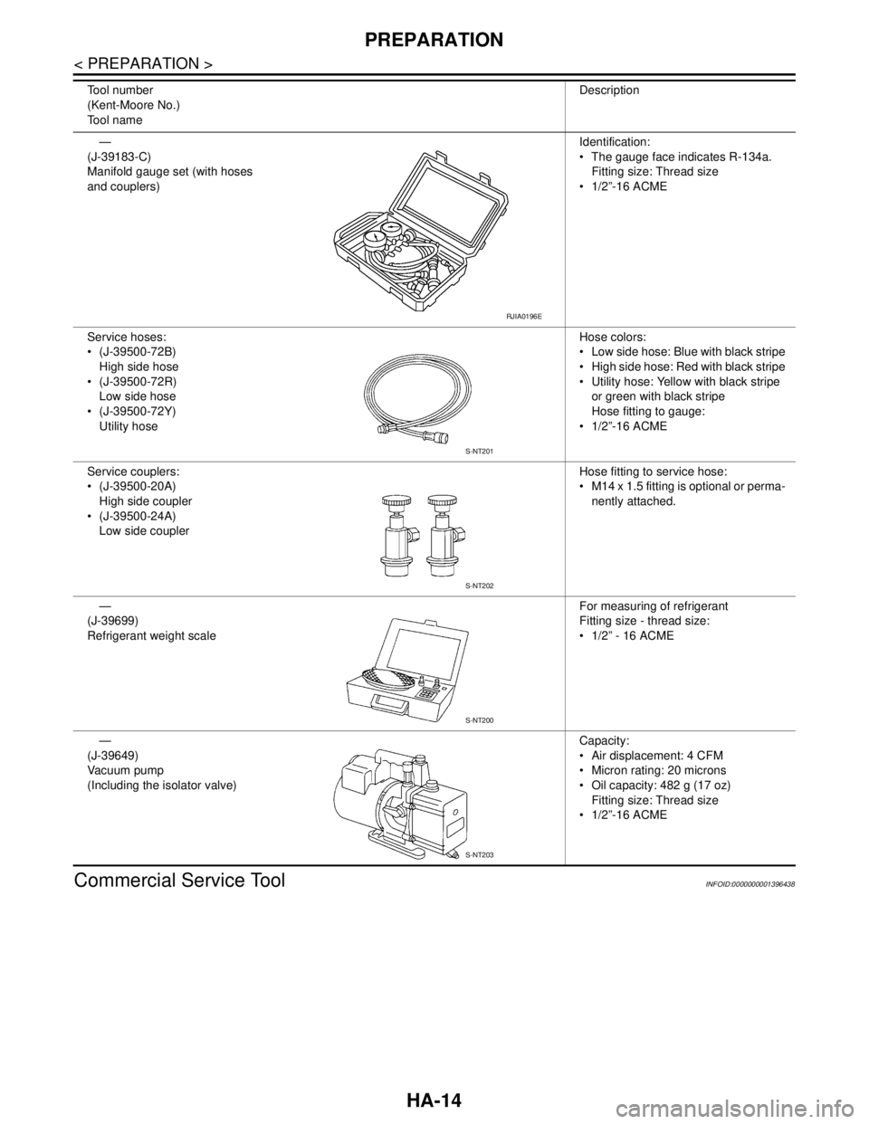
Commercial Service Tool
INFOID:0000000001396438
—
(J-39183-C)
Manifold gauge set (with hoses
and couplers)Identification:
The gauge face indicates R-134a.
Fitting size: Thread size
1/2”-16 ACME
Service hoses:
(J-39500-72B)
High side hose
(J-39500-72R)
Low side hose
(J-39500-72Y)
Utility hoseHose colors:
Low side hose: Blue with black stripe
High side hose: Red with black stripe
Utility hose: Yellow with black stripe
or green with black stripe
Hose fitting to gauge:
1/2”-16 ACME
Service couplers:
(J-39500-20A)
High side coupler
(J-39500-24A)
Low side couplerHose fitting to service hose:
M14 x 1.5 fitting is optional or perma-
nently attached.
—
(J-39699)
Refrigerant weight scaleFor measuring of refrigerant
Fitting size - thread size:
1/2” - 16 ACME
—
(J-39649)
Vacuum pump
(Including the isolator valve)Capacity:
Air displacement: 4 CFM
Micron rating: 20 microns
Oil capacity: 482 g (17 oz)
Fitting size: Thread size
1/2”-16 ACME Tool number
(Kent-Moore No.)
Tool nameDescription
RJIA0196E
S-NT201
S-NT202
S-NT200
S-NT203
Page 3332 of 5883

HA-50
< SERVICE DATA AND SPECIFICATIONS (SDS)
SERVICE DATA AND SPECIFICATIONS (SDS)
SERVICE DATA AND SPECIFICATIONS (SDS)
SERVICE DATA AND SPECIFICATIONS (SDS)
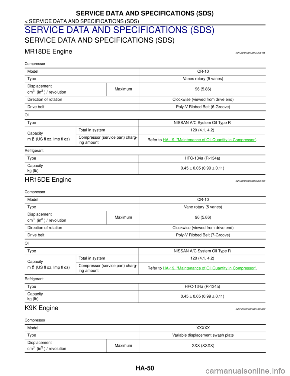
MR18DE EngineINFOID:0000000001396455
Compressor
Oil
Refrigerant
HR16DE EngineINFOID:0000000001396456
Compressor
Oil
Refrigerant
K9K EngineINFOID:0000000001396457
Compressor
ModelCR-10
Ty p eVanes rotary (5 vanes)
Displacement
cm
3 (in3 ) / revolutionMaximum 96 (5.86)
Direction of rotation Clockwise (viewed from drive end)
Drive beltPoly-V Ribbed Belt (6-Groove)
Ty p eNISSAN A/C System Oil Type R
Capacity
m (US fl oz, lmp fl oz)Total in system 120 (4.1, 4.2)
Compressor (service part) charg-
ing amountRefer to HA-19, "
Maintenance of Oil Quantity in Compressor".
Ty p eHFC-134a (R-134a)
Capacity
kg (lb)0.45 ± 0.05 (0.99 ± 0.11)
ModelCR-10
Ty p eVane rotary (5 vanes)
Displacement
cm
3 (in3 ) / revolutionMaximum 96 (5.86)
Direction of rotation Clockwise (viewed from drive end)
Drive beltPoly-V Ribbed Belt (7-Groove)
Ty p eNISSAN A/C System Oil Type R
Capacity
m (US fl oz, lmp fl oz)Total in system 120 (4.1, 4.2)
Compressor (service part) charg-
ing amountRefer to HA-19, "
Maintenance of Oil Quantity in Compressor".
Ty p eHFC-134a (R-134a)
Capacity
kg (lb)0.45 ± 0.05 (0.99 ± 0.11)
ModelXXXXX
Ty p eVariable displacement swash plate
Displacement
cm
3 (in3 ) / revolutionMaximum XXX (XXXX)
Page 3333 of 5883
SERVICE DATA AND SPECIFICATIONS (SDS)
HA-51
< SERVICE DATA AND SPECIFICATIONS (SDS)
C
D
E
F
G
H
J
K
L
MA
B
HA
N
O
P
Oil
Refrigerant
Direction of rotation Clockwise (viewed from drive end)
Drive beltPoly-V Ribbed Belt (6-Groove)
Typ eNISSAN A/C System Oil Type S
Capacity
m (US fl oz, lmp fl oz)Total in system 100 (3.4, 3.5)
Compressor (service part) charg-
ing amountRefer to HA-19, "
Maintenance of Oil Quantity in Compressor".
Typ eHFC-134a (R-134a)
Capacity
kg (lb)0.45 ± 0.05 (0.99 ± 0.11)
Page 4215 of 5883
LU-8
< ON-VEHICLE MAINTENANCE >[HR16DE]
ENGINE OIL
Refilling
INFOID:0000000001381529
1. Install drain plug with new washer. Refer to EM-100, "Exploded View".
CAUTION:
Be sure to clean drain plug and install with new washer.
2. Refill with new engine oil.
Engine oil specification and viscosity: Refer to MA-19, "
Fluids and Lubricants".
CAUTION:
The refill capacity depends on the engine oil temperature and drain time. Use these specifica-
tions for reference only.
Always use oil level gauge to determine the proper amount of engine oil in the engine.
3. Warm up engine and check area around drain plug and oil filter for engine oil leakage.
4. Stop engine and wait for 10 minutes.
5. Check the engine oil level. Refer to LU-6, "
Inspection". Drain plug : Refer to EM-100, "
Exploded View".
Page 4217 of 5883
LU-10
< SERVICE DATA AND SPECIFICATIONS (SDS) [HR16DE]
SERVICE DATA AND SPECIFICATIONS (SDS)
SERVICE DATA AND SPECIFICATIONS (SDS)
SERVICE DATA AND SPECIFICATIONS (SDS)
Periodical Maintenance SpecificationINFOID:0000000001381532
ENGINE OIL CAPACITY (APPROXIMATE)
Unit: (lmp qt)
Engine Oil PressureINFOID:0000000001381533
*: Engine oil temperature at 80°C (176°F)
Drain and refill With oil filter change 4.3 (3-3/4)
Without oil filter change 4.1 (3-5/8)
Dry engine (Overhaul)4.8 (4-1/4)
Engine speed (rpm)
Approximate discharge pressure* [kPa (bar, kg/cm2, psi)]
Idle speed More than 60 (0.60, 0.61, 9)
2,000 More than 270 (2.7, 2.8, 39)