2007 NISSAN TIIDA manual transmission
[x] Cancel search: manual transmissionPage 1 of 5883

MODEL C11 SERIES
2007 NISSAN EUROPE S.A.S.
All rights reserved. No part of this Electronic Service Manual may be reproduced or stored in a retrieval system, or transmitted in any form,
or by any means, electronic, mechanical, photocopying, recording or otherwise, without the prior written permission of Nissan Europe
S.A.S., Paris, France.
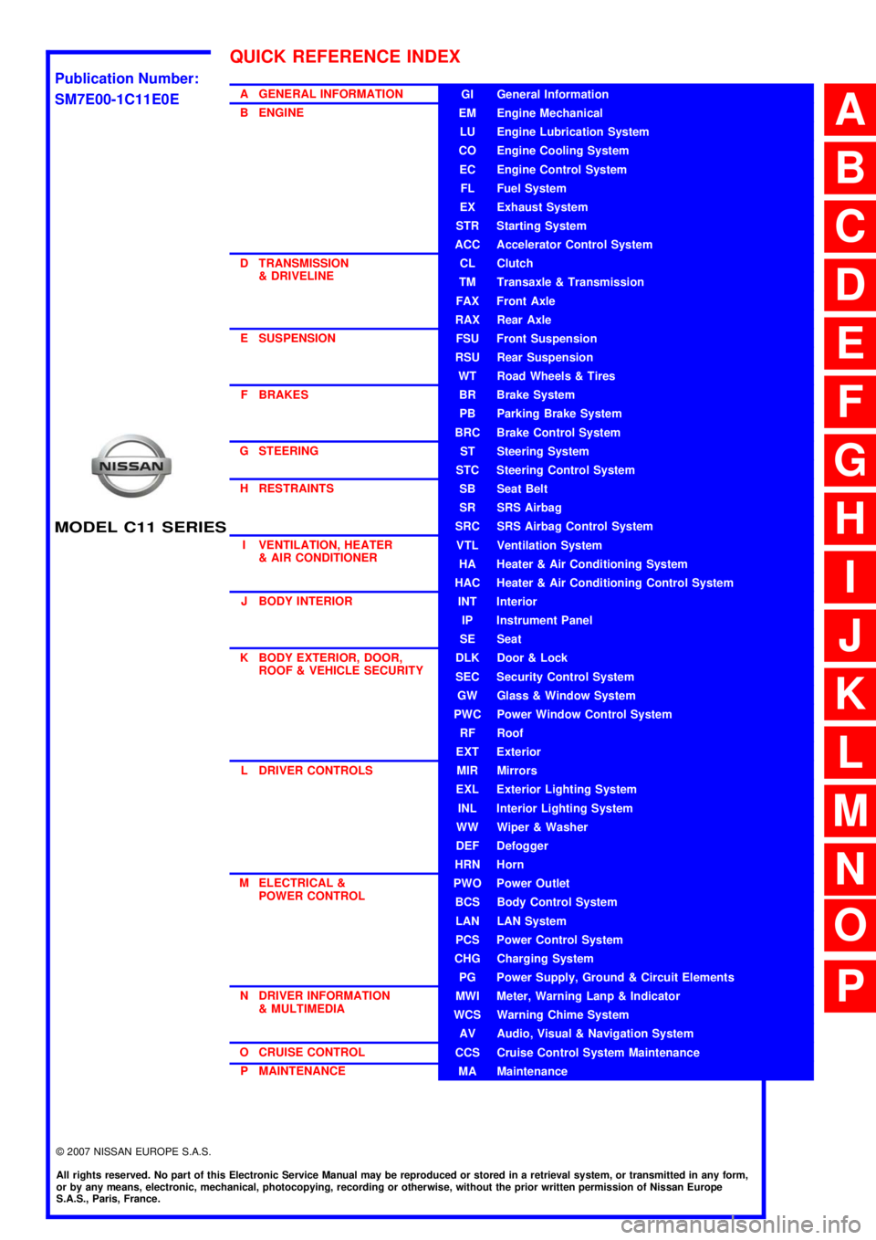
A GENERAL INFORMATION
B ENGINE
D TRANSMISSION& DRIVELINE
E SUSPENSION F BRAKES
G STEERING H RESTRAINTS
I VENTILATION, HEATER & AIR CONDITIONER
J BODY INTERIOR
K BODY EXTERIOR, DOOR, ROOF & VEHICLE SECURITY
L DRIVER CONTROLS
M ELECTRICAL & POWER CONTROL
N DRIVER INFORMATION & MULTIMEDIA
O CRUISE CONTROL P MAINTENANCEGI General Information
EM Engine Mechanical
LU Engine Lubrication System
CO Engine Cooling System
EC Engine Control System
FL Fuel System
EX Exhaust System
STR Starting System
ACC Accelerator Control System
CL Clutch
TM Transaxle & Transmission
FAX Front Axle
RAX Rear Axle
FSU Front Suspension
RSU Rear Suspension
WT Road Wheels & Tires
BR Brake System
PB Parking Brake System
BRC Brake Control System
ST Steering System
STC Steering Control System
SB Seat Belt
SR SRS Airbag
SRC SRS Airbag Control System
VTL Ventilation System
HA Heater & Air Conditioning System
HAC Heater & Air Conditioning Control System
INT Interior
IP Instrument Panel
SE Seat
DLK Door & Lock
SEC Security Control System
GW Glass & Window System
PWC Power Window Control System
RF Roof
EXT Exterior
MIR Mirrors
EXL Exterior Lighting System
INL Interior Lighting System
WW Wiper & Washer
DEF Defogger
HRN Horn
PWO Power Outlet
BCS Body Control System
LAN LAN System
PCS Power Control System
CHG Charging System
PG Power Supply, Ground & Circuit Elements
MWI Meter, Warning Lanp & Indicator
WCS Warning Chime System
AV Audio, Visual & Navigation System
CCS Cruise Control System Maintenance
MA Maintenance
QUICK REFERENCE INDEX
A
B
C
D
E
F
G
H
I
J
K
L
M
N
O
P
M
Publication Number:
SM7E00-1C11E0E
Page 646 of 5883
![NISSAN TIIDA 2007 Service Repair Manual U1010 CONTROL UNIT (CAN)
DLK-57
< COMPONENT DIAGNOSIS >[WITH I-KEY, WITHOUT SUPER LOCK]
C
D
E
F
G
H
I
J
L
MA
B
DLK
N
O
P
U1010 CONTROL UNIT (CAN)
DescriptionINFOID:0000000001396510
CAN (Controller Are NISSAN TIIDA 2007 Service Repair Manual U1010 CONTROL UNIT (CAN)
DLK-57
< COMPONENT DIAGNOSIS >[WITH I-KEY, WITHOUT SUPER LOCK]
C
D
E
F
G
H
I
J
L
MA
B
DLK
N
O
P
U1010 CONTROL UNIT (CAN)
DescriptionINFOID:0000000001396510
CAN (Controller Are](/manual-img/5/57395/w960_57395-645.png)
U1010 CONTROL UNIT (CAN)
DLK-57
< COMPONENT DIAGNOSIS >[WITH I-KEY, WITHOUT SUPER LOCK]
C
D
E
F
G
H
I
J
L
MA
B
DLK
N
O
P
U1010 CONTROL UNIT (CAN)
DescriptionINFOID:0000000001396510
CAN (Controller Area Network) is a serial communication line for real time applications. It is an on-vehicle mul-
tiplex communication line with high data communication speed and excellent error detection ability. Modern
vehicle is equipped with many electronic control unit, and each control unit shares information and links with
other control units during operation (not independent). In CAN communication, control units are connected
with 2 communication lines (CAN-H line, CAN-L line) allowing a high rate of information transmission with less
wiring. Each control unit transmits/receives data but selectively reads required data only.
CAN Communication Signal Chart, refer to XX-XX, "*****"
.
DTC LogicINFOID:0000000001396511
DTC DETECTION LOGIC
Diagnosis ProcedureINFOID:0000000001396512
1.REPLACE INTELLIGENT KEY UNIT
When DTC [U1010] is detected, replace Intelligent Key unit.
>> Replace Intelligent Key unit. Refer to SEC-79, "
Removal and Installation".
Special Repair RequirementINFOID:0000000001396513
1.REQUIRED WORK WHEN REPLACING INTELLIGENT KEY UNIT
Initialize control unit. Refer to CONSULT-III Operation Manual.
>> Work end.
DTCCONSULT-III display de-
scriptionDTC Detection Condition Possible cause
U1010 CONTROL UNIT (CAN)When detecting error during the initial diagnosis of CAN control-
ler of Intelligent Key unit.Intelligent Key unit
Page 871 of 5883
![NISSAN TIIDA 2007 Service Repair Manual DLK-282
< COMPONENT DIAGNOSIS >[WITH I-KEY & SUPER LOCK]
U1010 CONTROL UNIT (CAN)
U1010 CONTROL UNIT (CAN)
DescriptionINFOID:0000000001396718
CAN (Controller Area Network) is a serial communication li NISSAN TIIDA 2007 Service Repair Manual DLK-282
< COMPONENT DIAGNOSIS >[WITH I-KEY & SUPER LOCK]
U1010 CONTROL UNIT (CAN)
U1010 CONTROL UNIT (CAN)
DescriptionINFOID:0000000001396718
CAN (Controller Area Network) is a serial communication li](/manual-img/5/57395/w960_57395-870.png)
DLK-282
< COMPONENT DIAGNOSIS >[WITH I-KEY & SUPER LOCK]
U1010 CONTROL UNIT (CAN)
U1010 CONTROL UNIT (CAN)
DescriptionINFOID:0000000001396718
CAN (Controller Area Network) is a serial communication line for real time applications. It is an on-vehicle mul-
tiplex communication line with high data communication speed and excellent error detection ability. Modern
vehicle is equipped with many electronic control unit, and each control unit shares information and links with
other control units during operation (not independent). In CAN communication, control units are connected
with 2 communication lines (CAN-H line, CAN-L line) allowing a high rate of information transmission with less
wiring. Each control unit transmits/receives data but selectively reads required data only.
CAN Communication Signal Chart, refer to XX-XX, "*****"
.
DTC LogicINFOID:0000000001396719
DTC DETECTION LOGIC
Diagnosis ProcedureINFOID:0000000001396720
1.REPLACE INTELLIGENT KEY UNIT
When DTC [U1010] is detected, replace Intelligent Key unit.
>> Replace Intelligent Key unit. Refer to SEC-79, "
Removal and Installation".
Special Repair RequirementINFOID:0000000001396721
1.REQUIRED WORK WHEN REPLACING INTELLIGENT KEY UNIT
Initialize control unit. Refer to CONSULT-III operation manual.
>> Work end.
DTCCONSULT-III display de-
scriptionDTC Detection Condition Possible cause
U1010 CONTROL UNIT (CAN)When detecting error during the initial diagnosis of CAN control-
ler of Intelligent Key unit.Intelligent Key unit
Page 1082 of 5883
![NISSAN TIIDA 2007 Service Repair Manual U1010 CONTROL UNIT (CAN)
DLK-493
< COMPONENT DIAGNOSIS >[WITHOUT I-KEY & SUPER LOCK]
C
D
E
F
G
H
I
J
L
MA
B
DLK
N
O
P
U1010 CONTROL UNIT (CAN)
DescriptionINFOID:0000000001397027
CAN (Controller Area N NISSAN TIIDA 2007 Service Repair Manual U1010 CONTROL UNIT (CAN)
DLK-493
< COMPONENT DIAGNOSIS >[WITHOUT I-KEY & SUPER LOCK]
C
D
E
F
G
H
I
J
L
MA
B
DLK
N
O
P
U1010 CONTROL UNIT (CAN)
DescriptionINFOID:0000000001397027
CAN (Controller Area N](/manual-img/5/57395/w960_57395-1081.png)
U1010 CONTROL UNIT (CAN)
DLK-493
< COMPONENT DIAGNOSIS >[WITHOUT I-KEY & SUPER LOCK]
C
D
E
F
G
H
I
J
L
MA
B
DLK
N
O
P
U1010 CONTROL UNIT (CAN)
DescriptionINFOID:0000000001397027
CAN (Controller Area Network) is a serial communication line for real time applications. It is an on-vehicle mul-
tiplex communication line with high data communication speed and excellent error detection ability. Modern
vehicle is equipped with many electronic control unit, and each control unit shares information and links with
other control units during operation (not independent). In CAN communication, control units are connected
with 2 communication lines (CAN-H line, CAN-L line) allowing a high rate of information transmission with less
wiring. Each control unit transmits/receives data but selectively reads required data only.
CAN Communication Signal Chart, refer to XX-XX, "*****"
.
DTC LogicINFOID:0000000001397028
DTC DETECTION LOGIC
Diagnosis ProcedureINFOID:0000000001397029
1.REPLACE BCM
When DTC [U1010] is detected, replace BCM.
>> Replace BCM. Refer to BCS-57, "
Removal and Installation of BCM".
Special Repair RequirementINFOID:0000000001397030
1.REQUIRED WORK WHEN REPLACING INTELLIGENT KEY UNIT
Configure BCM. Refer to CONSULT-III operation manual.
>> Work end.
DTCCONSULT-III display de-
scriptionDTC Detection Condition Possible cause
U1010 CONTROL UNIT (CAN)When detecting error during the initial diagnosis of CAN control-
ler of BCMBCM
Page 1221 of 5883
![NISSAN TIIDA 2007 Service Repair Manual DLK-632
< COMPONENT DIAGNOSIS >[WITHOUT I-KEY, WITH SUPER LOCK]
U1010 CONTROL UNIT (CAN)
U1010 CONTROL UNIT (CAN)
DescriptionINFOID:0000000001397232
CAN (Controller Area Network) is a serial communica NISSAN TIIDA 2007 Service Repair Manual DLK-632
< COMPONENT DIAGNOSIS >[WITHOUT I-KEY, WITH SUPER LOCK]
U1010 CONTROL UNIT (CAN)
U1010 CONTROL UNIT (CAN)
DescriptionINFOID:0000000001397232
CAN (Controller Area Network) is a serial communica](/manual-img/5/57395/w960_57395-1220.png)
DLK-632
< COMPONENT DIAGNOSIS >[WITHOUT I-KEY, WITH SUPER LOCK]
U1010 CONTROL UNIT (CAN)
U1010 CONTROL UNIT (CAN)
DescriptionINFOID:0000000001397232
CAN (Controller Area Network) is a serial communication line for real time applications. It is an on-vehicle mul-
tiplex communication line with high data communication speed and excellent error detection ability. Modern
vehicle is equipped with many electronic control unit, and each control unit shares information and links with
other control units during operation (not independent). In CAN communication, control units are connected
with 2 communication lines (CAN-H line, CAN-L line) allowing a high rate of information transmission with less
wiring. Each control unit transmits/receives data but selectively reads required data only.
CAN Communication Signal Chart, refer to XX-XX, "*****"
.
DTC LogicINFOID:0000000001397233
DTC DETECTION LOGIC
Diagnosis ProcedureINFOID:0000000001397234
1.REPLACE BCM
When DTC [U1010] is detected, replace BCM.
>> Replace BCM. Refer to BCS-57, "
Removal and Installation of BCM".
Special Repair RequirementINFOID:0000000001397235
1.REQUIRED WORK WHEN REPLACING INTELLIGENT KEY UNIT
Initialize control unit. Refer to CONSULT-III operation manual.
>> Work end.
DTCCONSULT-III display de-
scriptionDTC Detection Condition Possible cause
U1010 CONTROL UNIT (CAN)When detecting error during the initial diagnosis of CAN control-
ler of BCM.BCM
Page 2856 of 5883
![NISSAN TIIDA 2007 Service Repair Manual ENGINE ASSEMBLY
EM-209
< REMOVAL AND INSTALLATION >[MR18DE]
C
D
E
F
G
H
I
J
K
L
MA
EM
N
P O
24. Remove the intake manifold to prevent the hanging chain from interfering. Refer to EM-156, "Removal
and NISSAN TIIDA 2007 Service Repair Manual ENGINE ASSEMBLY
EM-209
< REMOVAL AND INSTALLATION >[MR18DE]
C
D
E
F
G
H
I
J
K
L
MA
EM
N
P O
24. Remove the intake manifold to prevent the hanging chain from interfering. Refer to EM-156, "Removal
and](/manual-img/5/57395/w960_57395-2855.png)
ENGINE ASSEMBLY
EM-209
< REMOVAL AND INSTALLATION >[MR18DE]
C
D
E
F
G
H
I
J
K
L
MA
EM
N
P O
24. Remove the intake manifold to prevent the hanging chain from interfering. Refer to EM-156, "Removal
and Installation".
25. Install engine slinger to cylinder head front left side (A) and rear
right side (B) and support the engine position with a hoist.
26. Support engine and transaxle assembly with a hoist and secure the engine in appropriate position.
27. Use a manual lift table caddy (A) or equivalently rigid tool such
as a transmission jack. Securely support bottom of the engine
and the transaxle, and simultaneously adjust hoist tension.
CAUTION:
Put a piece of wood or something similar as the supporting
surface, secure a completely stable condition.
28. Remove torque rod (RH) (1), engine insulator (RH) (2) and
engine bracket (RH) (3).
29. Remove engine through bolt-securing nut (C).
30. Remove the engine and the transaxle assembly from the vehicle downward by carefully operating sup-
porting tools.
CAUTION:
During the operation, make sure that no part interferes with the vehicle side.
Before and during this lifting, always check if any harnesses are left connected.
During the removal operation, always be careful to prevent the vehicle from falling off the lift due
to changes in the center of gravity.
If necessary, support the vehicle by setting jack or suitable tool at the rear.
During operation, securely support the engine by placing a piece of wood under the engine oil
pan and transaxle oil pan. Securely support the engine slingers with a hoist.
31. When the engine hoisting is not performed simultaneously, install engine slinger to cylinder head front left
side and rear right side. Refer to EM-207, "
Component".
32. Remove starter motor. Refer to STR-24, "
Removal and Installation".
33. Lift with a hoist and position above engine.
34. Separate the engine and the transaxle. Refer to EM-207, "
Component" .
INSTALLATION
Note the following, and install in the reverse order of removal.
Do not allow engine oil to get on engine mounting insulator. Be careful not to damage engine mounting insu-
lator.
: Engine front
Slinger bolts : 25.5 N·m (2.6 kg-m, 19 ft-lb)
LBIA0461E
PBIC3223J
4 : Engine insulator (LH)
A : Engine front side
B : Transaxle side
WBIA0784E
Page 3197 of 5883

HOW TO USE THIS MANUAL
GI-3
< HOW TO USE THIS MANUAL >
C
D
E
F
G
H
I
J
K
L
MB
GI
N
O
PHOW TO USE THIS MANUAL
HOW TO USE THIS MANUAL
DescriptionINFOID:0000000001606142
This volume explains “Removal, Disassembly, Installation, Inspection and Adjustment” and “Trouble Diag-
noses”.
Te r m sINFOID:0000000001606143
The captions WARNING and CAUTION warn you of steps that must be followed to prevent personal injury
and/or damage to some part of the vehicle.
WARNING indicates the possibility of personal injury if instructions are not followed.
CAUTION indicates the possibility of component damage if instructions are not followed.
BOLD TYPED STATEMENTS except WARNING and CAUTION give you helpful information.
Standard value:Tolerance at inspection and adjustment.
Limit value:The maximum or minimum limit value that should not be exceeded at inspection and adjustment.
UnitsINFOID:0000000001606144
The UNITS given in this manual are primarily expressed as the SI UNIT (International System of Unit), and
alternatively expressed in the metric system and in the yard/pound system.
Also with regard to tightening torque of bolts and nuts, there are descriptions both about range and about the
standard tightening torque.
“Example”
Range
Standard
ContentsINFOID:0000000001606145
ALPHABETICAL INDEX is provided at the end of this manual so that you can rapidly find the item and page
you are searching for.
A QUICK REFERENCE INDEX, a black tab (e.g. ) is provided on the first page. You can quickly find the
first page of each section by matching it to the section's black tab.
THE CONTENTS are listed on the first page of each section.
THE TITLE is indicated on the upper portion of each page and shows the part or system.
THE PAGE NUMBER of each section consists of two or three letters which designate the particular section
and a number (e.g. “BR-5”).
THE SMALL ILLUSTRATIONS show the important steps such as inspection, use of special tools, knacks of
work and hidden or tricky steps which are not shown in the previous large illustrations.
Assembly, inspection and adjustment procedures for the complicated units such as the automatic transaxle
or transmission, etc. are presented in a step-by-step format where necessary. Outer Socket Lock Nut : 59 - 78 N·m (6.0 - 8.0 kg-m, 43 - 58 ft-lb)
Drive Shaft Installation Bolt: 44.3 N·m (4.5 kg-m, 33 ft-lb)
Page 3210 of 5883

GI-16
< HOW TO USE THIS MANUAL >
HOW TO USE THIS MANUAL
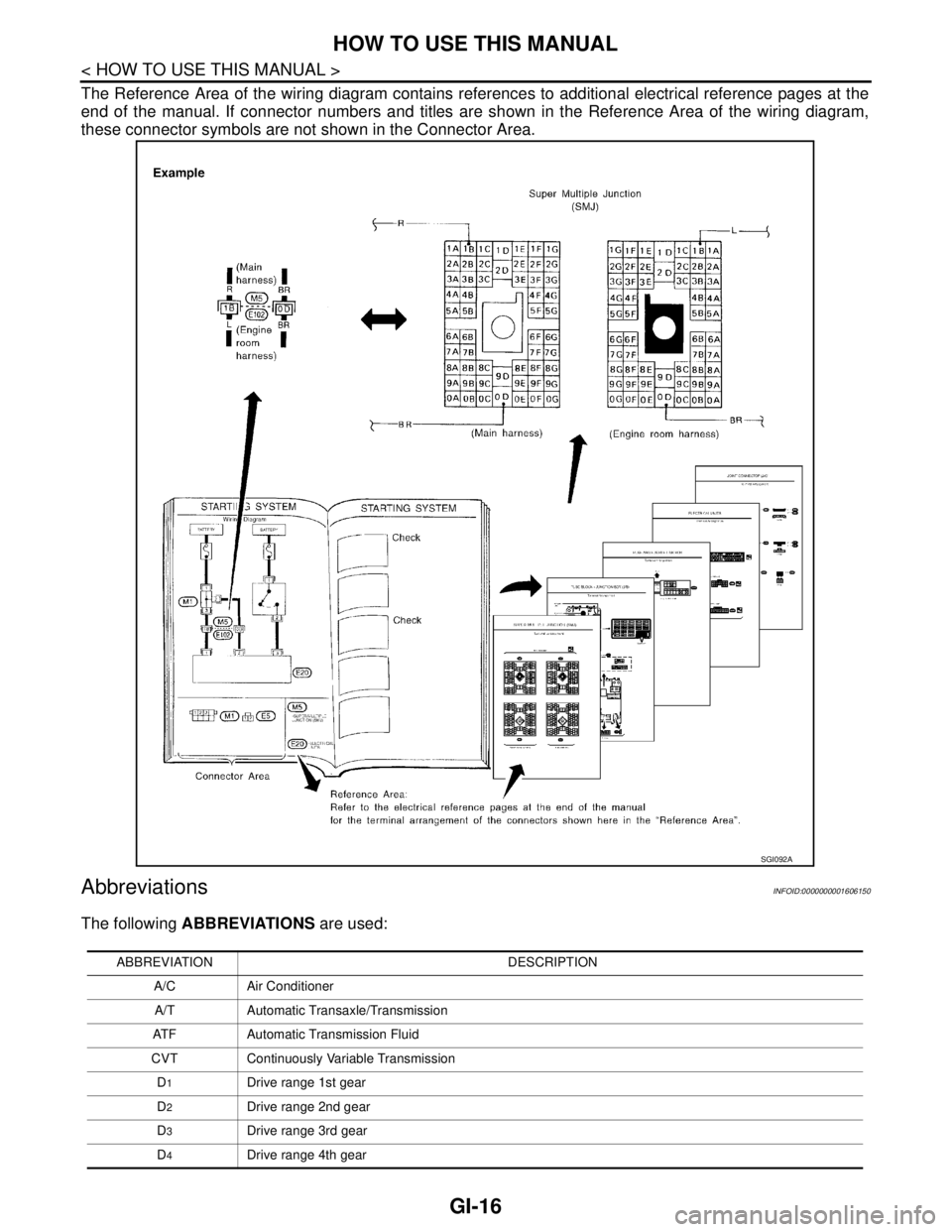
The Reference Area of the wiring diagram contains references to additional electrical reference pages at the
end of the manual. If connector numbers and titles are shown in the Reference Area of the wiring diagram,
these connector symbols are not shown in the Connector Area.
AbbreviationsINFOID:0000000001606150
The following ABBREVIATIONS are used:
SGI092A
ABBREVIATION DESCRIPTION
A/C Air Conditioner
A/T Automatic Transaxle/Transmission
ATF Automatic Transmission Fluid
CVT Continuously Variable Transmission
D
1Drive range 1st gear
D
2Drive range 2nd gear
D
3Drive range 3rd gear
D
4Drive range 4th gear