2007 NISSAN TIIDA Pri pressure
[x] Cancel search: Pri pressurePage 221 of 5883
REAR DISC BRAKE
BR-29
< ON-VEHICLE REPAIR >
C
D
E
G
H
I
J
K
L
MA
B
BR
N
O
P
3. Drain brake fluid. Refer to BR-8, "Bleeding Brake System".
4. Remove connecting bolt and torque member bolts using power tool, and remove cylinder body.
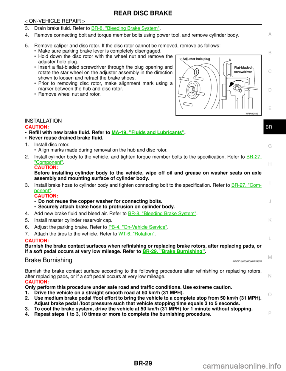
5. Remove caliper and disc rotor. If the disc rotor cannot be removed, remove as follows:
Make sure parking brake lever is completely disengaged.
Hold down the disc rotor with the wheel nut and remove the
adjuster hole plug.
Insert a flat-bladed screwdriver through the plug opening and
rotate the star wheel on the adjuster assembly in the direction
shown to loosen and retract the brake shoes.
Prior to removing disc rotor, make alignment mark using a
marker between the hub and disc rotor.
Remove wheel nut and rotor.
INSTALLATION
CAUTION:
Refill with new brake fluid. Refer to MA-19, "
Fluids and Lubricants".
Never reuse drained brake fluid.
1. Install disc rotor.
Align marks made during removal on the hub and disc rotor.
2. Install cylinder body to the vehicle, and tighten torque member bolts to the specification. Refer to BR-27,
"Component".
CAUTION:
Before installing cylinder body to the vehicle, wipe off oil and grease on washer seats on axle
assembly and mounting surface of cylinder body.
3. Install brake hose to cylinder body and tighten connecting bolt to the specification. Refer to BR-27, "
Com-
ponent".
CAUTION:
Do not reuse the copper washer for connecting bolts.
Securely attach brake hose to protrusion on cylinder body.
4. Add new brake fluid and bleed air. Refer to BR-8, "
Bleeding Brake System".
5. Install master cylinder reservoir cap.
6. Adjust the parking brake. Refer to PB-4, "
On-Vehicle Service".
7. Attach the tires to the vehicle. Refer to WT-6, "
Rotation".
CAUTION:
Burnish the brake contact surfaces when refinishing or replacing brake rotors, after replacing pads, or
if a soft pedal occurs at very low mileage. Refer to BR-29, "
Brake Burnishing".
Brake BurnishingINFOID:0000000001724670
Burnish the brake contact surface according to the following procedure after refinishing or replacing rotors,
after replacing pads, or if a soft pedal occurs at very low mileage.
CAUTION:
Only perform this procedure under safe road and traffic conditions. Use extreme caution.
1. Drive the vehicle on a straight smooth road at 50 km/h (31 MPH).
2. Use medium brake pedal /foot effort to bring the vehicle to a complete stop from 50 km/h (31 MPH).
Adjust brake pedal /foot pressure such that vehicle stopping time equals 3 to 5 seconds.
3. To cool the brake system, drive the vehicle at 50 km/h (31 MPH) for 1 minute without stopping.
4. Repeat steps 1 to 3, 10 times or more to complete the burnishing procedure.
WFIA0018E
Page 267 of 5883

BRC-34
< COMPONENT DIAGNOSIS >[ABS]
C1105, C1106, C1107, C1108 WHEEL SENSOR-2
2.CHECK WHEEL SENSOR OUTPUT SIGNAL
1. Connect ABS active wheel sensor tester (J-45741) to wheel sensor using appropriate adapter.
2. Turn on the ABS active wheel sensor tester power switch.
NOTE:
The green POWER indicator should illuminate. If the POWER indicator does not illuminate, replace the
battery in the ABS active wheel sensor tester before proceeding.
3. Spin the wheel of the vehicle by hand and observe the red SENSOR indicator on the ABS active wheel
sensor tester. The red SENSOR indicator should flash on and off to indicate an output signal.
NOTE:
If the red SENSOR indicator illuminates but does not flash, reverse the polarity of the tester leads and
retest.
Does the ABS active wheel sensor tester detect a signal?
YES >> GO TO 3
NO >> Replace the wheel sensor. Refer to BRC-83, "
Removal and Installation".
3.CHECK TIRES
Check for inflation pressure, wear and size of each tire.
Are tire pressure and size correct and is tire wear within specifications?
YES >> GO TO 4
NO >> Adjust tire pressure or replace tire(s).
4.CHECK WHEEL BEARINGS
Check wheel bearing axial end play. Refer to FAX-5, "
On-Vehicle Inspection and Service" (front) or RAX-5,
"On-Vehicle Inspection and Service" (rear).
Is the inspection result normal?
YES >> GO TO 5
NO >> Repair or replace as necessary. Refer to FA X - 7 , "
Removal and Installation" (front) or RAX-6,
"Removal and Installation" (rear).
5.CHECK WIRING HARNESS FOR SHORT CIRCUIT
1. Disconnect ABS actuator and electric unit (control unit) connec-
tor and wheel sensor connector of malfunction code No.
2. Check continuity between wheel sensor harness connector ter-
minals and ground.
Is the inspection result normal?
YES >> GO TO 6
NO >> Repair the circuit.
6.CHECK WIRING HARNESS FOR OPEN CIRCUIT
1. Check continuity between ABS actuator and electric unit (control unit) harness connector E125 and the
malfunctioning wheel sensor harness connector E18, E117, C10, or C11. Continuity should not exist.
WFIA0343E
Page 312 of 5883

NORMAL OPERATING CONDITION
BRC-79
< SYMPTOM DIAGNOSIS >[ABS]
C
D
E
G
H
I
J
K
L
MA
B
BRC
N
O
P
NORMAL OPERATING CONDITION
DescriptionINFOID:0000000001731350
Symptom Result
Slight vibrations are felt on the brake pedal and the operation noises occur, when VDC, TCS or ABS is acti-
vated.
This is a normal condi-
tion due to the VDC,
TCS or ABS activation. Stopping distance is longer than that of vehicles without ABS when the vehicle drives on rough, gravel, or
snow-covered (fresh, deep snow) roads.
The brake pedal moves and generates noises, when TCS or VDC is activated due to rapid acceleration or
sharp turn.
The brake pedal vibrates and motor operation noises occur from the engine room, after the engine starts and
just after the vehicle starts.This is normal, and it is
caused by the ABS op-
eration check.
Depending on the road conditions, the driver may experience a sluggish feel. This is normal, because
TCS places the highest
priority on the optimum
traction (stability). TCS may activate momentarily if wheel speed changes when driving over location where friction coefficient
varies, when downshifting, or when fully depressing accelerator pedal.
The ABS warning lamp, VDC OFF indicator lamp and SLIP indicator lamp may turn ON when the vehicle is
subject to strong shaking or large vibration, such as when the vehicle is rotating on a turntable or located on
a ship while the engine is running. In this case, restart the
engine on a normal
road. If the normal con-
dition is restored, there
is no malfunction. At
that time, erase the self-
diagnosis memory. VDC may not operate normally or the ABS warning lamp, VDC OFF indicator lamp, and SLIP indicator lamp
may illuminate, when running on a special road that is extremely slanted (e.g. bank in a circuit course).
A malfunction may occur in the yaw rate/side/decel G sensor system, when the vehicle turns sharply, such
as during a spin turn, axle turn, or drift driving, while the VDC function is off (VDC OFF indicator lamp illumi-
nated).
The vehicle speed will not increase even though the accelerator pedal is depressed, when inspecting the
speedometer on a 2-wheel chassis dynamometer. Normal (Deactivate the
VDC/TCS function be-
fore performing an in-
spection on a chassis
dynamometer.)
VDC OFF indicator lamp and SLIP indicator lamp may simultaneously turn on when low tire pressure warn-
ing lamp turns on.This is not a VDC sys-
tem error but results
from characteristic
change of tire.
Page 347 of 5883

BRC-114
< COMPONENT DIAGNOSIS >[ESP/TCS/ABS]
C1105, C1106, C1107, C1108 WHEEL SENSOR-2
2.CHECK WHEEL SENSOR OUTPUT SIGNAL
1. Connect ABS active wheel sensor tester (J-45741) to wheel sensor using appropriate adapter.
2. Turn on the ABS active wheel sensor tester power switch.
NOTE:
The green POWER indicator should illuminate. If the POWER indicator does not illuminate, replace the
battery in the ABS active wheel sensor tester before proceeding.
3. Spin the wheel of the vehicle by hand and observe the red SENSOR indicator on the ABS active wheel
sensor tester. The red SENSOR indicator should flash on and off to indicate an output signal.
NOTE:
If the red SENSOR indicator illuminates but does not flash, reverse the polarity of the tester leads and
retest.
Does the ABS active wheel sensor tester detect a signal?
YES >> GO TO 3
NO >> Replace the wheel sensor. Refer to BRC-182, "
Removal and Installation".
3.CHECK TIRES
Check for inflation pressure, wear and size of each tire.
Are tire pressure and size correct and is tire wear within specifications?
YES >> GO TO 4
NO >> Adjust tire pressure or replace tire(s).
4.CHECK WHEEL BEARINGS
Check wheel bearing axial end play. Refer to FAX-5, "
On-Vehicle Inspection and Service" (front) or RAX-5,
"On-Vehicle Inspection and Service" (rear).
Is the inspection result normal?
YES >> GO TO 5
NO >> Repair or replace as necessary. Refer to FA X - 7 , "
Removal and Installation" (front) or RAX-6,
"Removal and Installation" (rear).
5.CHECK WIRING HARNESS FOR SHORT CIRCUIT
1. Disconnect ABS actuator and electric unit (control unit) connec-
tor and wheel sensor connector of malfunction code No.
2. Check continuity between wheel sensor harness connector ter-
minals and ground.
Is the inspection result normal?
YES >> GO TO 6
NO >> Repair the circuit.
6.CHECK WIRING HARNESS FOR OPEN CIRCUIT
1. Check continuity between ABS actuator and electric unit (control unit) harness connector E125 and the
malfunctioning wheel sensor harness connector E18, E117, C10, or C11. Continuity should not exist.
WFIA0343E
Page 411 of 5883

BRC-178
< SYMPTOM DIAGNOSIS >[ESP/TCS/ABS]
NORMAL OPERATING CONDITION
NORMAL OPERATING CONDITION
DescriptionINFOID:0000000001731207
Symptom Result
Slight vibrations are felt on the brake pedal and the operation noises occur, when VDC, TCS or ABS is acti-
vated.
This is a normal condi-
tion due to the VDC,
TCS or ABS activation. Stopping distance is longer than that of vehicles without ABS when the vehicle drives on rough, gravel, or
snow-covered (fresh, deep snow) roads.
The brake pedal moves and generates noises, when TCS or VDC is activated due to rapid acceleration or
sharp turn.
The brake pedal vibrates and motor operation noises occur from the engine room, after the engine starts and
just after the vehicle starts.This is normal, and it is
caused by the ABS op-
eration check.
Depending on the road conditions, the driver may experience a sluggish feel. This is normal, because
TCS places the highest
priority on the optimum
traction (stability). TCS may activate momentarily if wheel speed changes when driving over location where friction coefficient
varies, when downshifting, or when fully depressing accelerator pedal.
The ABS warning lamp, VDC OFF indicator lamp and SLIP indicator lamp may turn ON when the vehicle is
subject to strong shaking or large vibration, such as when the vehicle is rotating on a turntable or located on
a ship while the engine is running. In this case, restart the
engine on a normal
road. If the normal con-
dition is restored, there
is no malfunction. At
that time, erase the self-
diagnosis memory. VDC may not operate normally or the ABS warning lamp, VDC OFF indicator lamp, and SLIP indicator lamp
may illuminate, when running on a special road that is extremely slanted (e.g. bank in a circuit course).
A malfunction may occur in the yaw rate/side/decel G sensor system, when the vehicle turns sharply, such
as during a spin turn, axle turn, or drift driving, while the VDC function is off (VDC OFF indicator lamp illumi-
nated).
The vehicle speed will not increase even though the accelerator pedal is depressed, when inspecting the
speedometer on a 2-wheel chassis dynamometer. Normal (Deactivate the
VDC/TCS function be-
fore performing an in-
spection on a chassis
dynamometer.)
VDC OFF indicator lamp and SLIP indicator lamp may simultaneously turn on when low tire pressure warn-
ing lamp turns on.This is not a VDC sys-
tem error but results
from characteristic
change of tire.
Page 437 of 5883

CHG-16
< SERVICE DATA AND SPECIFICATIONS (SDS) [HR16DE]
SERVICE DATA AND SPECIFICATIONS (SDS)
SERVICE DATA AND SPECIFICATIONS (SDS)
SERVICE DATA AND SPECIFICATIONS (SDS)
GeneratorINFOID:0000000001689489
Applied modelHR16DE
Ty p eA2TJ0291ZE
MITSUBISHI
Nominal rating [V - A] 12 - 120
Ground polarityNegative
Minimum revolution under no-load (When 13.5
V is applied)[rpm] Less than 1,300
Hot output current (When 13.5 V is applied) [A/rpm]More than 27/1,300
More than 95/2,500
More than 116/5,000
Regulated output voltage [V] 14.1 - 14.7
Minimum length of brush [mm (in)] More than 5.00 (0.197)
Brush spring pressure [N (g, oz)] 4.1 - 5.3 (418 - 541, 14.7 - 19.1)
Slip ring minimum outer diameter [mm (in)] More than 22.1 (0.870)
Rotor (Field coil) resistance [Ω] 1.7 - 2.2
Page 451 of 5883

CHG-30
< SERVICE DATA AND SPECIFICATIONS (SDS) [MR18DE]
SERVICE DATA AND SPECIFICATIONS (SDS)
SERVICE DATA AND SPECIFICATIONS (SDS)
SERVICE DATA AND SPECIFICATIONS (SDS)
GeneratorINFOID:0000000001690788
Ty p eH90-128SC
MITSUBISHI make
Nominal rating12 V - 90 A
Ground polarityNegative
Minimum revolution under no-load (when 13.5 V is applied) Less than 1,200 rpm
Hot output current (when 13.5 V is applied)More than 27 A/1,300 rpm
More than 76 A/2,500 rpm
More than 85 A/5,000 rpm
Regulated output voltage14.1 - 14.7 V
Minimum length of brush More than 6.00 mm (0.236 in)
Brush spring pressure 1.1 - 3.7 N (112 - 378 g, 4.00 - 13.3 oz)
Slip ring minimum outer diameter More than 14.7 mm (0.579 in)
Rotor (field coil) resistance 1.61 - 1.91 Ω
Page 465 of 5883

CHG-44
< SERVICE DATA AND SPECIFICATIONS (SDS) [K9K]
SERVICE DATA AND SPECIFICATIONS (SDS)
SERVICE DATA AND SPECIFICATIONS (SDS)
SERVICE DATA AND SPECIFICATIONS (SDS)
GeneratorINFOID:0000000001691231
Applied modelK9K
Ty p e0 124 525 082
BOSCH make
Nominal rating [V - A] —
Ground polarity—
Minimum revolution under no-load (When 13.5 V
is applied)[rpm] —
Hot output current (When 13.5 V is applied) [A/rpm] —
Regulated output voltage [V] —
Minimum length of brush [mm (in)] —
Brush spring pressure [N (g, oz)] —
Slip ring minimum outer diameter [mm (in)] —
Rotor (Field coil) resistance [Ω]—