2007 NISSAN TIIDA automatic transmission
[x] Cancel search: automatic transmissionPage 2446 of 5883
![NISSAN TIIDA 2007 Service Repair Manual COOLING FAN CONTROL
EC-1097
< FUNCTION DIAGNOSIS >[K9K]
C
D
E
F
G
H
I
J
K
L
MA
EC
N
P O
COOLING FAN CONTROL
System DescriptionINFOID:0000000001162544
The cooling fan motor is controlled by the ECM.
CO NISSAN TIIDA 2007 Service Repair Manual COOLING FAN CONTROL
EC-1097
< FUNCTION DIAGNOSIS >[K9K]
C
D
E
F
G
H
I
J
K
L
MA
EC
N
P O
COOLING FAN CONTROL
System DescriptionINFOID:0000000001162544
The cooling fan motor is controlled by the ECM.
CO](/manual-img/5/57395/w960_57395-2445.png)
COOLING FAN CONTROL
EC-1097
< FUNCTION DIAGNOSIS >[K9K]
C
D
E
F
G
H
I
J
K
L
MA
EC
N
P O
COOLING FAN CONTROL
System DescriptionINFOID:0000000001162544
The cooling fan motor is controlled by the ECM.
COOLING FAN OPERATION WITH THE ENGINE RUNNING
Cooling fan operate is guaranteed by a 2-speed fan assembly (LOW speed and HIGH speed).The ECM
requests the IPDM E/R to actuate them via the can communication. To provide cooling:
Engine running
- LOW speed is actuated when the engine coolant temperature exceeds 96 °C (205°F) and is deactivated
when it drops below 94 °C (201°F).
- HIGH speed is actuated when the engine coolant temperature exceeds 104 °C (219°F) and is deactivated
when it drops below 102 °C (216°F).
If the engine coolant temperature exceeds the threshold of 115°C (239°F), the ECM requests the IPDM E/R,
via the CAN communication, to switch off the air conditioning compressor so as to reduce the load on the
engine and attempt to limit the rise in temperature. The cut-off request is cancelled if the engine coolant tem-
perature drops below 110°C (230°F).
If a malfunction in the engine coolant temperature sensor circuit is detected, the ECM requests that HIGH
speed operation.
In addition to engine management, the ECM centralises the cooling requirements for the climate control and
automatic transmission/sequential gearbox functions (where fitted).
Page 2582 of 5883
![NISSAN TIIDA 2007 Service Repair Manual ECM
EC-1233
< ECU DIAGNOSIS >[K9K]
C
D
E
F
G
H
I
J
K
L
MA
EC
N
P O Test Condition: Engine at Idle
Order Function Parameter Display and notes Trouble diagnosis
1 Fan speed request*FAN ASSEMBLY INACTIVE NISSAN TIIDA 2007 Service Repair Manual ECM
EC-1233
< ECU DIAGNOSIS >[K9K]
C
D
E
F
G
H
I
J
K
L
MA
EC
N
P O Test Condition: Engine at Idle
Order Function Parameter Display and notes Trouble diagnosis
1 Fan speed request*FAN ASSEMBLY INACTIVE](/manual-img/5/57395/w960_57395-2581.png)
ECM
EC-1233
< ECU DIAGNOSIS >[K9K]
C
D
E
F
G
H
I
J
K
L
MA
EC
N
P O Test Condition: Engine at Idle
Order Function Parameter Display and notes Trouble diagnosis
1 Fan speed request*FAN ASSEMBLY INACTIVE
NONE. FAN UNIT LOW -
FAN UNIT HIGH -
2Compressor
engagement requestDMND LNK COMPThe ECM requests the IPDM E/R
(via CAN communication line) to
start the compressor
ACTIVE: The CAN communica-
tion should not be suspected on
the Automatic Transmission,
IPDM E/R or Intelligent Key unit
or BCM system.
The Intelligent Key unit or BCM
should request the ECM to be
engaged.
The refrigerant pressure sensor
should not be suspected. Satis-
factory engine operating condi-
tions (engine coolant
temperature, engine load etc.).
INACTIVE: One of the above
conditions has not been met.NONE
3Fast idle speed re-
questACCEL IDL RQ INACTIVE NONE
4 Refrigerant pressureRFRGERNT PRSSIndicates the value in Bar for the
refrigerant fluid in the system.
Default value: 0 Bar.In the event of a malfunction, per-
form the trouble diagnosis for DTC
P0530 REFRUGERANT PRES-
SURE SENSOR.
RFRGERNT FLUID V 0.1V < RFRGERNT FLUID V <
4.8V
5Engine coolant tem-
peratureWATER TEMPClose to ambient temperature
(cold engine).
Indicates the engine coolant tem-
perature in °C.In the event of a malfunction, per-
form the trouble diagnosis for DTC
P0115 ECT SENSOR.
6 Vehicle speed VEHICLE SPEED0 km/h (mph)
Indicates the vehicle speed in km/h
(mph). This parameter is transmit-
ted by the “ABS actuator and elec-
tric unit (control unit)” or
combination meter via CAN com-
munication line.Perform the trouble diagnosis for
CAN communication line. Perform
the trouble diagnosis for “ABS ac-
tuator and electric unit (control
unit)” or combination meter.
Order Function Parameter Display and notes Trouble diagnosis
1 Fan speed request*FAN ASSEMBLY INACTIVE
NONE. FAN UNIT LOW -
FAN UNIT HIGH -
Page 2583 of 5883
![NISSAN TIIDA 2007 Service Repair Manual EC-1234
< ECU DIAGNOSIS >[K9K]
ECM
CRUISE CONTROL/SPEED LIMITER SUB FUNCTION
Test Condition: Engine Stopped and Ignition Switch ON
Test Condition: Engine at Idle
PROTECTION SUBFUNCTION
Test Condition: NISSAN TIIDA 2007 Service Repair Manual EC-1234
< ECU DIAGNOSIS >[K9K]
ECM
CRUISE CONTROL/SPEED LIMITER SUB FUNCTION
Test Condition: Engine Stopped and Ignition Switch ON
Test Condition: Engine at Idle
PROTECTION SUBFUNCTION
Test Condition:](/manual-img/5/57395/w960_57395-2582.png)
EC-1234
< ECU DIAGNOSIS >[K9K]
ECM
CRUISE CONTROL/SPEED LIMITER SUB FUNCTION
Test Condition: Engine Stopped and Ignition Switch ON
Test Condition: Engine at Idle
PROTECTION SUBFUNCTION
Test Condition: Engine Stopped and Ignition Switch ON
2Compressor
engagement re-
questDMND LNK COMPThe ECM requests the IPDM E/R
(via CAN communication line) to
start the compressor
ACTIVE: The CAN communica-
tion should not be suspected on
the Automatic Transmission,
IPDM E/R or Intelligent Key unit
or BCM system.
The Intelligent Key unit or BCM
should request the ECM to be en-
gaged.
The refrigerant pressure sensor
should not be suspected. Satis-
factory engine operating condi-
tions (engine coolant
temperature, engine load etc.).
INACTIVE: One of the above
conditions has not been met.NONE
3Fast idle speed re-
questACCEL IDL RQINACTIVE
or
ACTIVE
(Air conditioning is operate)NONE
4Refrigerant pres-
sureRFRGERNT PRSSIndicates the value in Bar for the re-
frigerant fluid in the system.
Default value: 0 Bar.In the event of a malfunction, per-
form the trouble diagnosis for DTC
P0530 REFRUGERANT PRES-
SURE SENSOR.
RFRGERNT FLUID V 0.1V < RFRGERNT FLUID V< 4.8V
5Engine coolant
temperatureWATER TEMPIndicates the engine coolant tem-
perature in °C.In the event of a malfunction, per-
form the trouble diagnosis for DTC
P0115 ECT SENSOR.
6 Vehicle speed VEHICLE SPEED0 km/h (mph)
Indicates the vehicle speed in km/h
(mph). This parameter is transmit-
ted by the “ABS actuator and elec-
tric unit (control unit)” or
combination meter via CAN com-
munication line.Perform the trouble diagnosis for
CAN communication line. Perform
the trouble diagnosis for “ABS actu-
ator and electric unit (control unit)”
or combination meter. Order Function Parameter Display and notes Trouble diagnosis
Order Function Parameter Display and notes Trouble diagnosis
1Cruise control/speed
limiterCRS CN/S LMTR INACTIVEIn the event of a malfunction, per-
form the trouble diagnosis for DTC
P0575 ASCD STEERING SWITCH.
Order Function Parameter Display and notes Trouble diagnosis
1Cruise control/speed
limiterCRS CN/S LMTR INACTIVEIn the event of a malfunction, perform
the trouble diagnosis for DTC P0575
ASCD STEERING SWITCH.
Page 3197 of 5883

HOW TO USE THIS MANUAL
GI-3
< HOW TO USE THIS MANUAL >
C
D
E
F
G
H
I
J
K
L
MB
GI
N
O
PHOW TO USE THIS MANUAL
HOW TO USE THIS MANUAL
DescriptionINFOID:0000000001606142
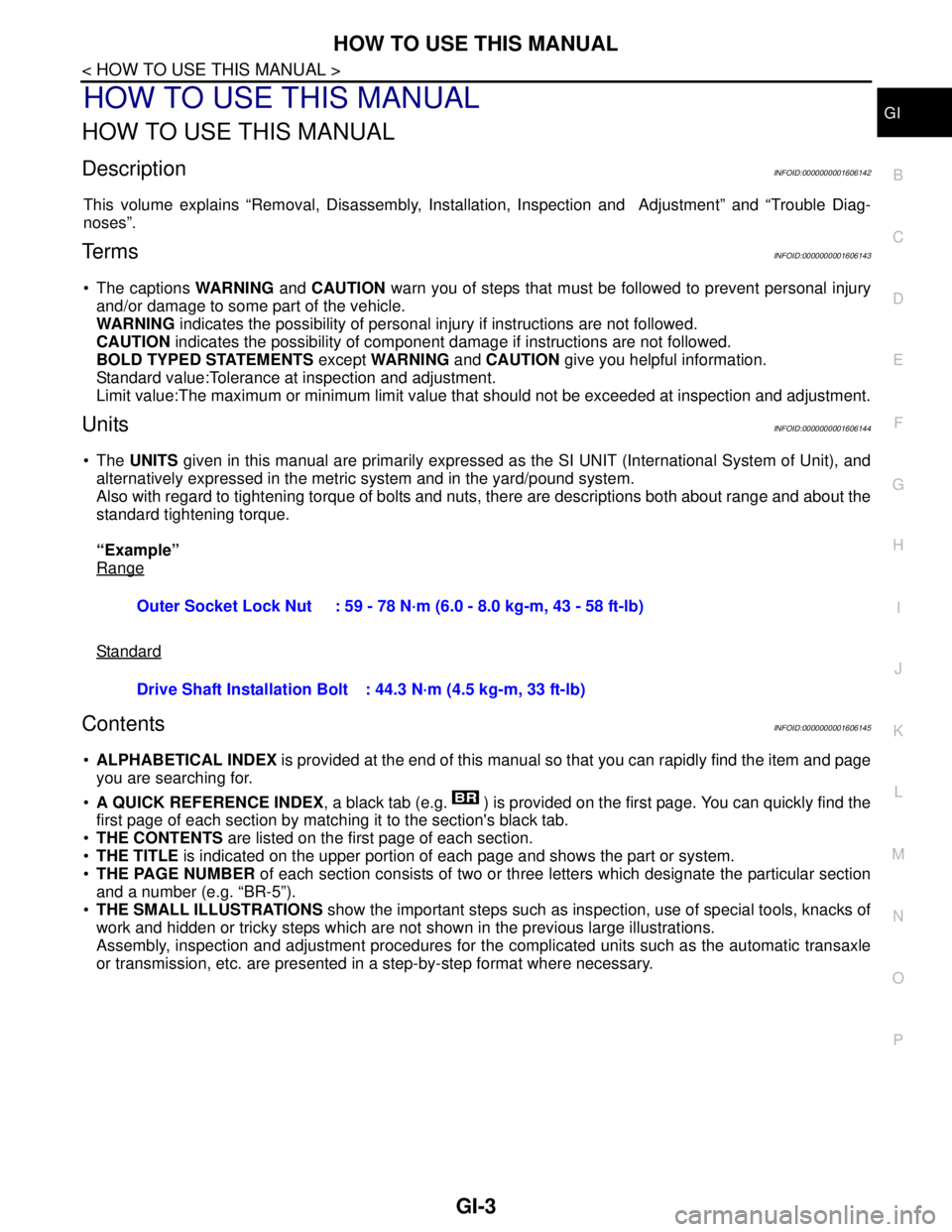
This volume explains “Removal, Disassembly, Installation, Inspection and Adjustment” and “Trouble Diag-
noses”.
Te r m sINFOID:0000000001606143
The captions WARNING and CAUTION warn you of steps that must be followed to prevent personal injury
and/or damage to some part of the vehicle.
WARNING indicates the possibility of personal injury if instructions are not followed.
CAUTION indicates the possibility of component damage if instructions are not followed.
BOLD TYPED STATEMENTS except WARNING and CAUTION give you helpful information.
Standard value:Tolerance at inspection and adjustment.
Limit value:The maximum or minimum limit value that should not be exceeded at inspection and adjustment.
UnitsINFOID:0000000001606144
The UNITS given in this manual are primarily expressed as the SI UNIT (International System of Unit), and
alternatively expressed in the metric system and in the yard/pound system.
Also with regard to tightening torque of bolts and nuts, there are descriptions both about range and about the
standard tightening torque.
“Example”
Range
Standard
ContentsINFOID:0000000001606145
ALPHABETICAL INDEX is provided at the end of this manual so that you can rapidly find the item and page
you are searching for.
A QUICK REFERENCE INDEX, a black tab (e.g. ) is provided on the first page. You can quickly find the
first page of each section by matching it to the section's black tab.
THE CONTENTS are listed on the first page of each section.
THE TITLE is indicated on the upper portion of each page and shows the part or system.
THE PAGE NUMBER of each section consists of two or three letters which designate the particular section
and a number (e.g. “BR-5”).
THE SMALL ILLUSTRATIONS show the important steps such as inspection, use of special tools, knacks of
work and hidden or tricky steps which are not shown in the previous large illustrations.
Assembly, inspection and adjustment procedures for the complicated units such as the automatic transaxle
or transmission, etc. are presented in a step-by-step format where necessary. Outer Socket Lock Nut : 59 - 78 N·m (6.0 - 8.0 kg-m, 43 - 58 ft-lb)
Drive Shaft Installation Bolt: 44.3 N·m (4.5 kg-m, 33 ft-lb)
Page 3210 of 5883

GI-16
< HOW TO USE THIS MANUAL >
HOW TO USE THIS MANUAL
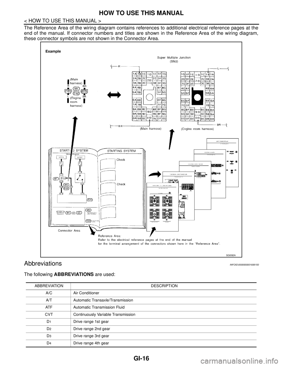
The Reference Area of the wiring diagram contains references to additional electrical reference pages at the
end of the manual. If connector numbers and titles are shown in the Reference Area of the wiring diagram,
these connector symbols are not shown in the Connector Area.
AbbreviationsINFOID:0000000001606150
The following ABBREVIATIONS are used:
SGI092A
ABBREVIATION DESCRIPTION
A/C Air Conditioner
A/T Automatic Transaxle/Transmission
ATF Automatic Transmission Fluid
CVT Continuously Variable Transmission
D
1Drive range 1st gear
D
2Drive range 2nd gear
D
3Drive range 3rd gear
D
4Drive range 4th gear
Page 3219 of 5883

ABBREVIATIONS
GI-25
< HOW TO USE THIS MANUAL >
C
D
E
F
G
H
I
J
K
L
MB
GI
N
O
PABBREVIATIONS
Abbreviation ListINFOID:0000000001691463
The following ABBREVIATIONS are used:
ABBREVIATION DESCRIPTION
A/C Air Conditioner
A/T Automatic Transaxle/Transmission
ATF Automatic Transmission Fluid
AWD All wheel drive
D
1Drive range 1st gear
D
2Drive range 2nd gear
D
3Drive range 3rd gear
D
4Drive range 4th gear
FR, RR Front, Rear
LH, RH Left-Hand, Right-Hand
OD Overdrive
P/S Power Steering
SAE Society of Automotive Engineers, Inc.
SDS Service Data and Specifications
SST Special Service Tools
2WD 2-Wheel Drive
2
22nd range 2nd gear
2
12nd range 1st gear
1
21st range 2nd gear
1
11st range 1st gear
Page 3221 of 5883

RECOMMENDED CHEMICAL PRODUCTS AND SEALANTS
GI-27
< HOW TO USE THIS MANUAL >
C
D
E
F
G
H
I
J
K
L
MB
GI
N
O
PRECOMMENDED CHEMICAL PRODUCTS AND SEALANTS
Recommended Chemical Products and SealantsINFOID:0000000001691465
Refer to the following chart for help in selecting the appropriate chemical product or sealant.
Product Description PurposeNissan North America
Part No. (USA)Nissan Canada Part
No. (Canada)Aftermarket Cross-
reference Part Nos.
1Rear View Mirror Adhe-
siveUsed to permanently re-
mount rear view mirrors to
windows.999MP-AM000P 99998-50505 Permatex 81844
2Anaerobic Liquid Gas-
ketFor metal-to-metal flange
sealing.
Can fill a 0.38 mm (0.015
inch) gap and provide in-
stant sealing for most pow-
ertrain applications.999MP-AM001P 99998-50503Permatex 51813 and
51817
3High Performance
Thread SealantProvides instant sealing on
any threaded straight or
parallel threaded fitting.
(Thread sealant only, no
locking ability.)
Do not use on plastic.999MP-AM002P 999MP-AM002P Permatex 56521
4 Silicone RTVGasket Maker999MP-AM003P
(Ultra Grey)99998-50506
(Ultra Grey)Permatex Ultra Grey
82194;
Three Bond
1207,1215, 1216,
1217F, 1217G and
1217H
Nissan RTV Part No.
999MP-A7007
Gasket Maker for Maxima/
Quest 5-speed automatic
transmission
(RE5F22A)––Three Bond 1281B
or exact equivalent in
its quality
5High Temperature,
High Strength Thread
Locking Sealant (Red)Threadlocker 999MP-AM004P 999MP-AM004PPermatex 27200;
Three Bond 1360,
1360N, 1305 N&P,
1307N, 1335,
1335B, 1363B,
1377C, 1386B, D&E
and 1388
Loctite 648
6Medium Strength
Thread Locking Seal-
ant (Blue)Threadlocker (service tool
removable)999MP-AM005P 999MP-AM005PPermatex 24200,
24206, 24240,
24283 and 09178;
Three Bond 1322,
1322N, 1324 D&N,
1333D, 1361C,
1364D, 1370C and
1374
Page 3238 of 5883

GI-44
< PRECAUTION >
PRECAUTIONS
General Precaution
INFOID:0000000001606118
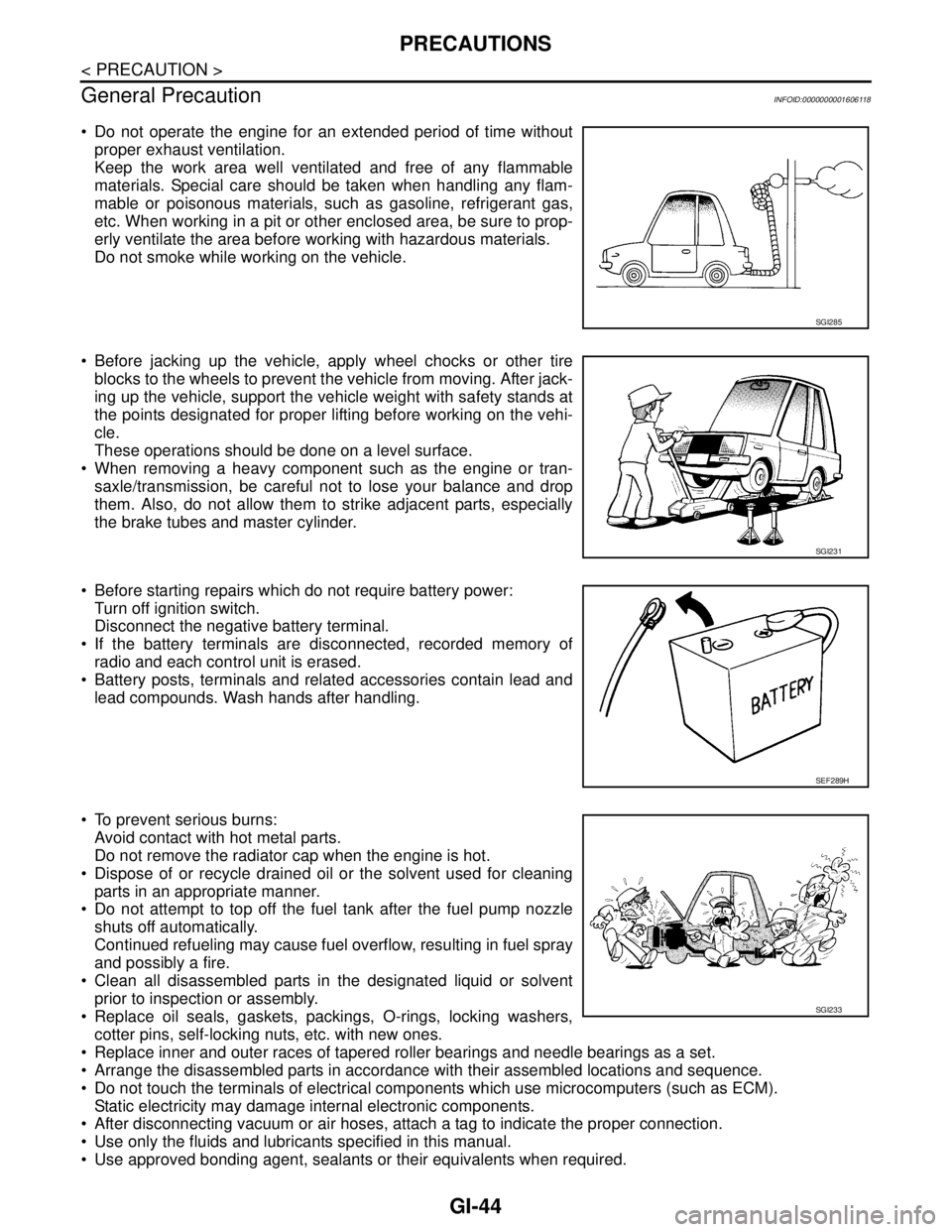
Do not operate the engine for an extended period of time without
proper exhaust ventilation.
Keep the work area well ventilated and free of any flammable
materials. Special care should be taken when handling any flam-
mable or poisonous materials, such as gasoline, refrigerant gas,
etc. When working in a pit or other enclosed area, be sure to prop-
erly ventilate the area before working with hazardous materials.
Do not smoke while working on the vehicle.
Before jacking up the vehicle, apply wheel chocks or other tire
blocks to the wheels to prevent the vehicle from moving. After jack-
ing up the vehicle, support the vehicle weight with safety stands at
the points designated for proper lifting before working on the vehi-
cle.
These operations should be done on a level surface.
When removing a heavy component such as the engine or tran-
saxle/transmission, be careful not to lose your balance and drop
them. Also, do not allow them to strike adjacent parts, especially
the brake tubes and master cylinder.
Before starting repairs which do not require battery power:
Turn off ignition switch.
Disconnect the negative battery terminal.
If the battery terminals are disconnected, recorded memory of
radio and each control unit is erased.
Battery posts, terminals and related accessories contain lead and
lead compounds. Wash hands after handling.
To prevent serious burns:
Avoid contact with hot metal parts.
Do not remove the radiator cap when the engine is hot.
Dispose of or recycle drained oil or the solvent used for cleaning
parts in an appropriate manner.
Do not attempt to top off the fuel tank after the fuel pump nozzle
shuts off automatically.
Continued refueling may cause fuel overflow, resulting in fuel spray
and possibly a fire.
Clean all disassembled parts in the designated liquid or solvent
prior to inspection or assembly.
Replace oil seals, gaskets, packings, O-rings, locking washers,
cotter pins, self-locking nuts, etc. with new ones.
Replace inner and outer races of tapered roller bearings and needle bearings as a set.
Arrange the disassembled parts in accordance with their assembled locations and sequence.
Do not touch the terminals of electrical components which use microcomputers (such as ECM).
Static electricity may damage internal electronic components.
After disconnecting vacuum or air hoses, attach a tag to indicate the proper connection.
Use only the fluids and lubricants specified in this manual.
Use approved bonding agent, sealants or their equivalents when required.
SGI285
SGI231
SEF289H
SGI233