2007 NISSAN TIIDA reverse
[x] Cancel search: reversePage 4758 of 5883
DIAGNOSIS SENSOR UNIT
SR-15
< ON-VEHICLE REPAIR >
C
D
E
F
G
I
J
K
L
MA
B
SR
N
O
P
DIAGNOSIS SENSOR UNIT
Removal and InstallationINFOID:0000000001350512
REMOVAL
WARNING:
Before disconnecting diagnosis sensor unit harness connector(s), be sure to disconnect harness con-
nectors from air bag modules and front seat belt pre-tensioner to prevent deployment by static elec-
tricity.
CAUTION:
Before servicing the SRS, turn the ignition switch OFF, disconnect both battery cables and wait at
least 3 minutes.
Do not disassemble diagnosis sensor unit.
Do not use old bolts; replace with new bolts.
Replace the diagnosis sensor unit if it has been dropped or sustained an impact.
Check diagnosis sensor unit bracket to make sure it is free of deformities, dents, cracks or rust. If it
shows any visible signs of damage, replace with new one.
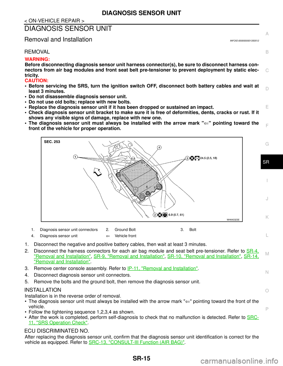
The diagnosis sensor unit must always be installed with the arrow mark "⇐" pointing toward the
front of the vehicle for proper operation.
1. Disconnect the negative and positive battery cables, then wait at least 3 minutes.
2. Disconnect the harness connectors for each air bag module and seat belt pre-tensioner. Refer to SR-4,
"Removal and Installation", SR-9, "Removal and Installation", SR-10, "Removal and Installation", SR-14,
"Removal and Installation".
3. Remove center console assembly. Refer to IP-11, "
Removal and Installation".
4. Disconnect diagnosis sensor unit connectors.
5. Remove the bolts and the ground bolt, then remove the diagnosis sensor unit.
INSTALLATION
Installation is in the reverse order of removal.
The diagnosis sensor unit must always be installed with the arrow mark "⇐" pointing toward the front of the
vehicle.
Follow the tightening sequence 1,2,3,4 as shown.
After the work is completed, perform self-diagnosis to check that no malfunction is detected. Refer to SRC-
11 , "SRS Operation Check".
ECU DISCRIMINATED NO.
After replacing the diagnosis sensor unit, confirm that the diagnosis sensor unit identification is correct for the
vehicle as equipped. Refer to SRC-13, "
CONSULT-III Function (AIR BAG)".
1. Diagnosis sensor unit connectors 2. Ground Bolt 3. Bolt
4. Diagnosis sensor unit⇐Vehicle front
WHIA0323E
Page 4759 of 5883
SR-16
< ON-VEHICLE REPAIR >
DISPOSAL OF AIR BAG MODULE AND SEAT BELT PRE-TENSIONER
DISPOSAL OF AIR BAG MODULE AND SEAT BELT PRE-TENSIONER
Caution for Air Bag Module and Seat Belt Pre-tensionerINFOID:0000000001404296
Before disposing of air bag module and seat belt pre-tensioner, or vehicles equipped with such systems,
deploy the systems. If such systems have already been deployed due to an accident, dispose of them as
indicated in Disposing of Air Bag Module and Seat Belt Pre-tensioner.
When deploying the air bag module and seat belt pre-tensioner,always use the Special Service Tool; Deploy-
ment tool (SST: KV99106400).
When deploying the air bag module and seat belt pre-tensioner,stand at least 5 m (16 ft) away from the
deployment component.
When deploying air bag module and seat belt pre-tensioner, a fairlyloud noise is made, followed by smoke
being released. The smoke is not poisonous,however, be careful not to inhale smoke since it irritates the
throat and can cause choking.
Always activate one air bag module at a time.
Due to heat, leave air bag module unattended for more than 30 minutes after deployment. Also leave seat
belt pre-tensioner unattended for more than 10 minutes after deployment.
Wear gloves when handling a deployed air bag module and seat belt pre-tensioner.
Never apply water to the deployed air bag module and seat belt pre-tensioner.
Wash your hands after finishing work.
Place the vehicle outdoors with an open space of at least 6 m (20 ft) on all sides when deploying air bag
module and seat belt pre-tensioner while mounted in vehicle.
Use a volt meter to make sure the vehicle battery is fully charged.
Do not dispose of the air bag module and seat belt pre-tensioner undeployed.
CHECKING DEPLOYMENT TOOL
Connecting to Battery
CAUTION:
The battery must show voltage of 9.6 V or more.
Remove the battery from the vehicle and place it on dry wood blocks
approximately 5 m (16 ft) away from the vehicle.
Wait 3 minutes after the vehicle battery is disconnected before pro-
ceeding.
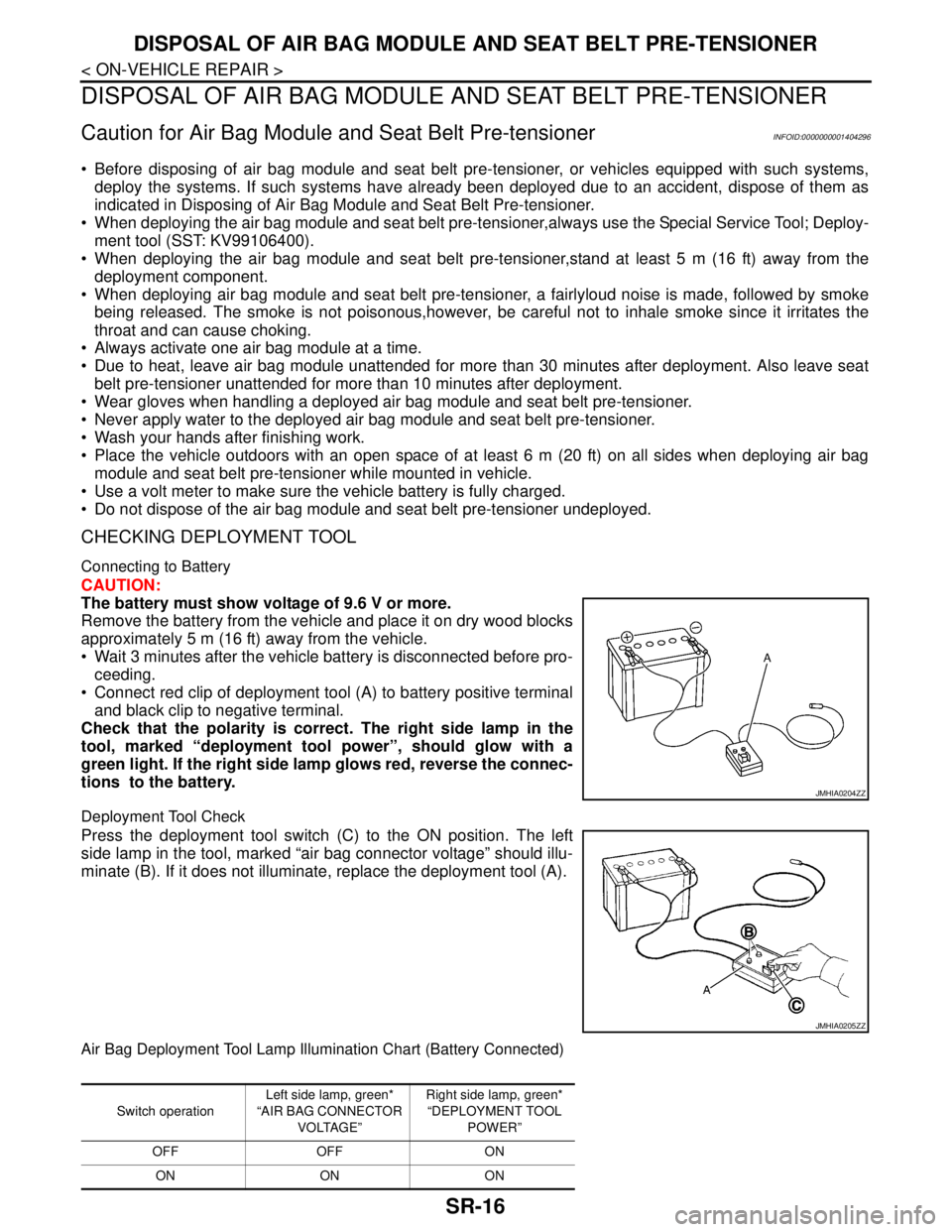
Connect red clip of deployment tool (A) to battery positive terminal
and black clip to negative terminal.
Check that the polarity is correct. The right side lamp in the
tool, marked “deployment tool power”, should glow with a
green light. If the right side lamp glows red, reverse the connec-
tions to the battery.
Deployment Tool Check
Press the deployment tool switch (C) to the ON position. The left
side lamp in the tool, marked “air bag connector voltage” should illu-
minate (B). If it does not illuminate, replace the deployment tool (A).
Air Bag Deployment Tool Lamp Illumination Chart (Battery Connected)
JMHIA0204ZZ
JMHIA0205ZZ
Switch operationLeft side lamp, green*
“AIR BAG CONNECTOR
VOLTAGE”Right side lamp, green*
“DEPLOYMENT TOOL
POWER”
OFF OFF ON
ON ON ON
Page 4760 of 5883
DISPOSAL OF AIR BAG MODULE AND SEAT BELT PRE-TENSIONER
SR-17
< ON-VEHICLE REPAIR >
C
D
E
F
G
I
J
K
L
MA
B
SR
N
O
P
*: If this lamp glows red, the tool is connected to the battery incorrectly.Reverse the connections and check the lamp glows green.
DEPLOYMENT OF AIR BAG MODULE (OUTSIDE OF VEHICLE)
Deployment of Driver Air Bag Module (Outside of Vehicle)
1. Unless the vehicle is being scrapped, deploying the air bag in
the vehicle is not recommended. This may cause damage to the
vehicle interior.
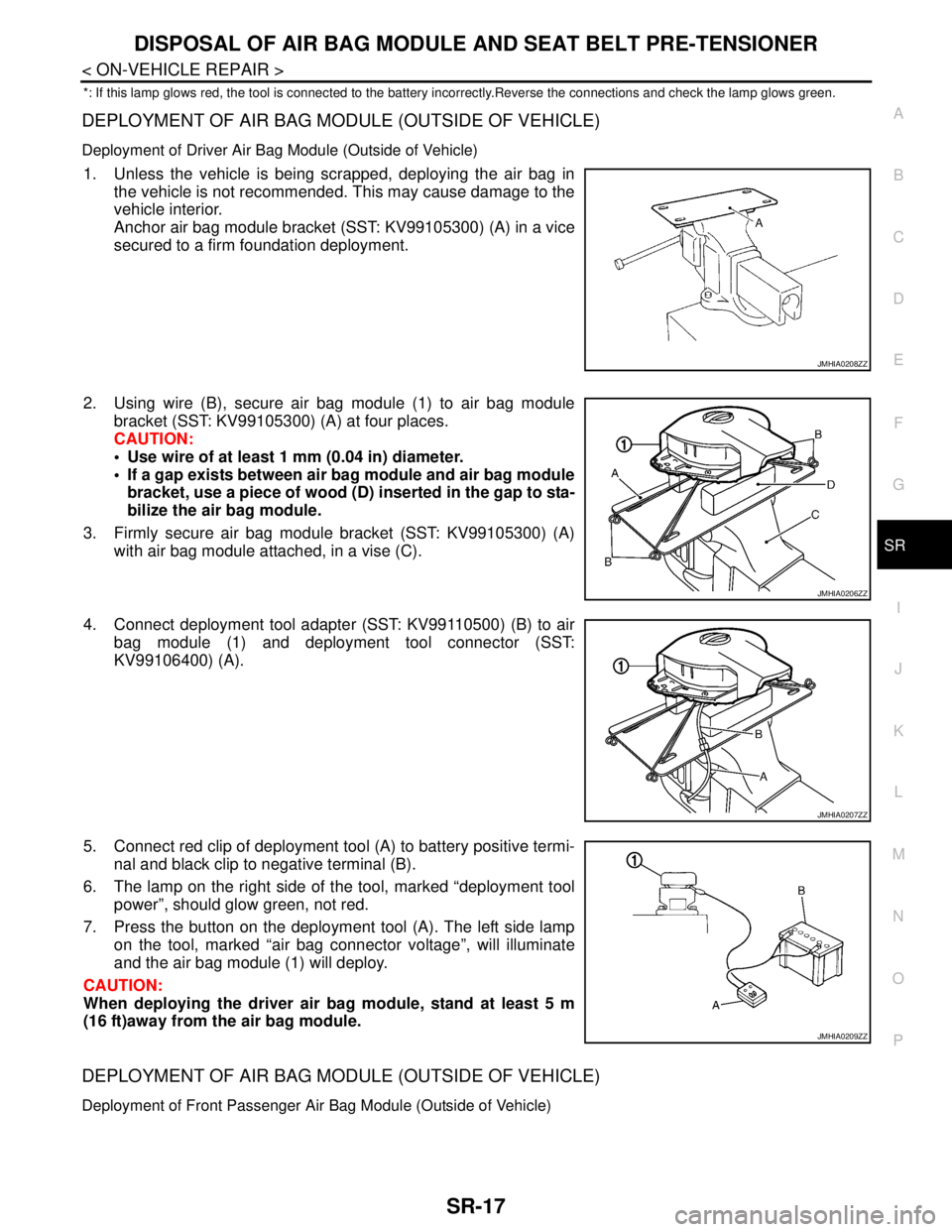
Anchor air bag module bracket (SST: KV99105300) (A) in a vice
secured to a firm foundation deployment.
2. Using wire (B), secure air bag module (1) to air bag module
bracket (SST: KV99105300) (A) at four places.
CAUTION:
Use wire of at least 1 mm (0.04 in) diameter.
If a gap exists between air bag module and air bag module
bracket, use a piece of wood (D) inserted in the gap to sta-
bilize the air bag module.
3. Firmly secure air bag module bracket (SST: KV99105300) (A)
with air bag module attached, in a vise (C).
4. Connect deployment tool adapter (SST: KV99110500) (B) to air
bag module (1) and deployment tool connector (SST:
KV99106400) (A).
5. Connect red clip of deployment tool (A) to battery positive termi-
nal and black clip to negative terminal (B).
6. The lamp on the right side of the tool, marked “deployment tool
power”, should glow green, not red.
7. Press the button on the deployment tool (A). The left side lamp
on the tool, marked “air bag connector voltage”, will illuminate
and the air bag module (1) will deploy.
CAUTION:
When deploying the driver air bag module, stand at least 5 m
(16 ft)away from the air bag module.
DEPLOYMENT OF AIR BAG MODULE (OUTSIDE OF VEHICLE)
Deployment of Front Passenger Air Bag Module (Outside of Vehicle)
JMHIA0208ZZ
JMHIA0206ZZ
JMHIA0207ZZ
JMHIA0209ZZ
Page 4863 of 5883
ST-8
< ON-VEHICLE REPAIR >
STEERING WHEEL
ON-VEHICLE REPAIR
STEERING WHEEL
Removal and InstallationINFOID:0000000001282499
REMOVAL
NOTE:
When reconnecting spiral cable, secure cable with a tape so that case and rotating part keep aligned. This will
omit neutral position alignment procedure during spiral cable installation.
1. Set front wheels to straight-ahead position.
2. Remove driver air bag module. Refer to SR-4, "
Removal and Installation" .
3. Remove steering wheel lock nut after steering is locked.
4. Remove steering wheel.
INSTALLATION
Installation is in the reverse order of removal.
CAUTION:
Do not run spiral cable idle needlessly. And do not turn it more than necessary (or it leads to discon-
nection of the cable).
NOTE:
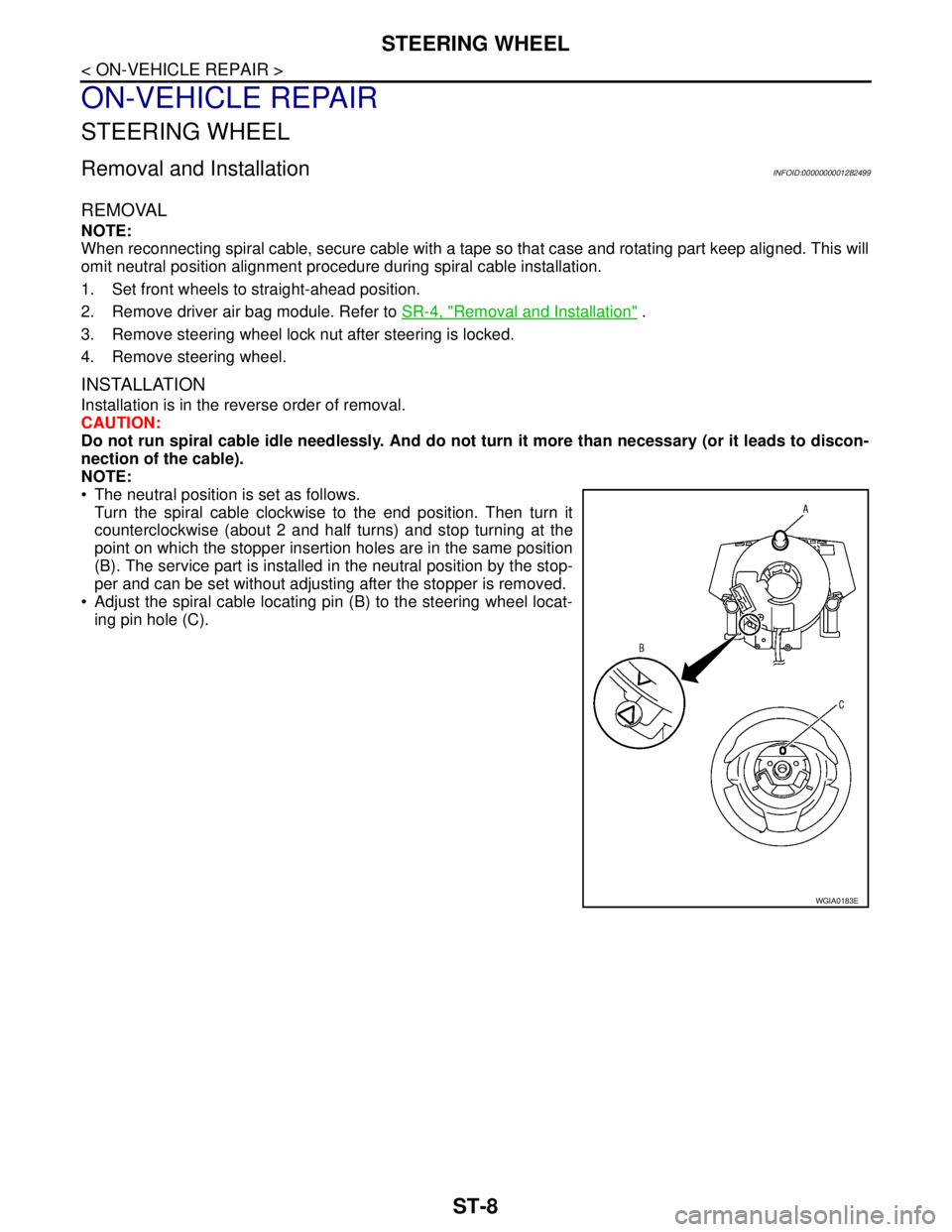
The neutral position is set as follows.
Turn the spiral cable clockwise to the end position. Then turn it
counterclockwise (about 2 and half turns) and stop turning at the
point on which the stopper insertion holes are in the same position
(B). The service part is installed in the neutral position by the stop-
per and can be set without adjusting after the stopper is removed.
Adjust the spiral cable locating pin (B) to the steering wheel locat-
ing pin hole (C).
WGIA0183E
Page 4865 of 5883
ST-10
< ON-VEHICLE REPAIR >
STEERING COLUMN
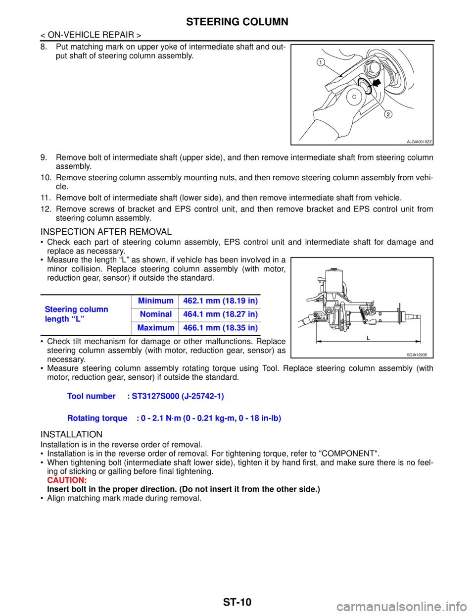
8. Put matching mark on upper yoke of intermediate shaft and out-
put shaft of steering column assembly.
9. Remove bolt of intermediate shaft (upper side), and then remove intermediate shaft from steering column
assembly.
10. Remove steering column assembly mounting nuts, and then remove steering column assembly from vehi-
cle.
11. Remove bolt of intermediate shaft (lower side), and then remove intermediate shaft from vehicle.
12. Remove screws of bracket and EPS control unit, and then remove bracket and EPS control unit from
steering column assembly.
INSPECTION AFTER REMOVAL
Check each part of steering column assembly, EPS control unit and intermediate shaft for damage and
replace as necessary.
Measure the length “L” as shown, if vehicle has been involved in a
minor collision. Replace steering column assembly (with motor,
reduction gear, sensor) if outside the standard.
Check tilt mechanism for damage or other malfunctions. Replace
steering column assembly (with motor, reduction gear, sensor) as
necessary.
Measure steering column assembly rotating torque using Tool. Replace steering column assembly (with
motor, reduction gear, sensor) if outside the standard.
INSTALLATION
Installation is in the reverse order of removal.
Installation is in the reverse order of removal. For tightening torque, refer to "COMPONENT".
When tightening bolt (intermediate shaft lower side), tighten it by hand first, and make sure there is no feel-
ing of sticking or galling before final tightening.
CAUTION:
Insert bolt in the proper direction. (Do not insert it from the other side.)
Align matching mark made during removal.
ALGIA0019ZZ
Steering column
length “L”Minimum 462.1 mm (18.19 in)
Nominal 464.1 mm (18.27 in)
Maximum 466.1 mm (18.35 in)
Tool number : ST3127S000 (J-25742-1)
Rotating torque : 0 - 2.1 N·m (0 - 0.21 kg-m, 0 - 18 in-lb)
SGIA1293E
Page 4867 of 5883
ST-12
< ON-VEHICLE REPAIR >
STEERING GEAR
STEERING GEAR
Removal and InstallationINFOID:0000000001282501
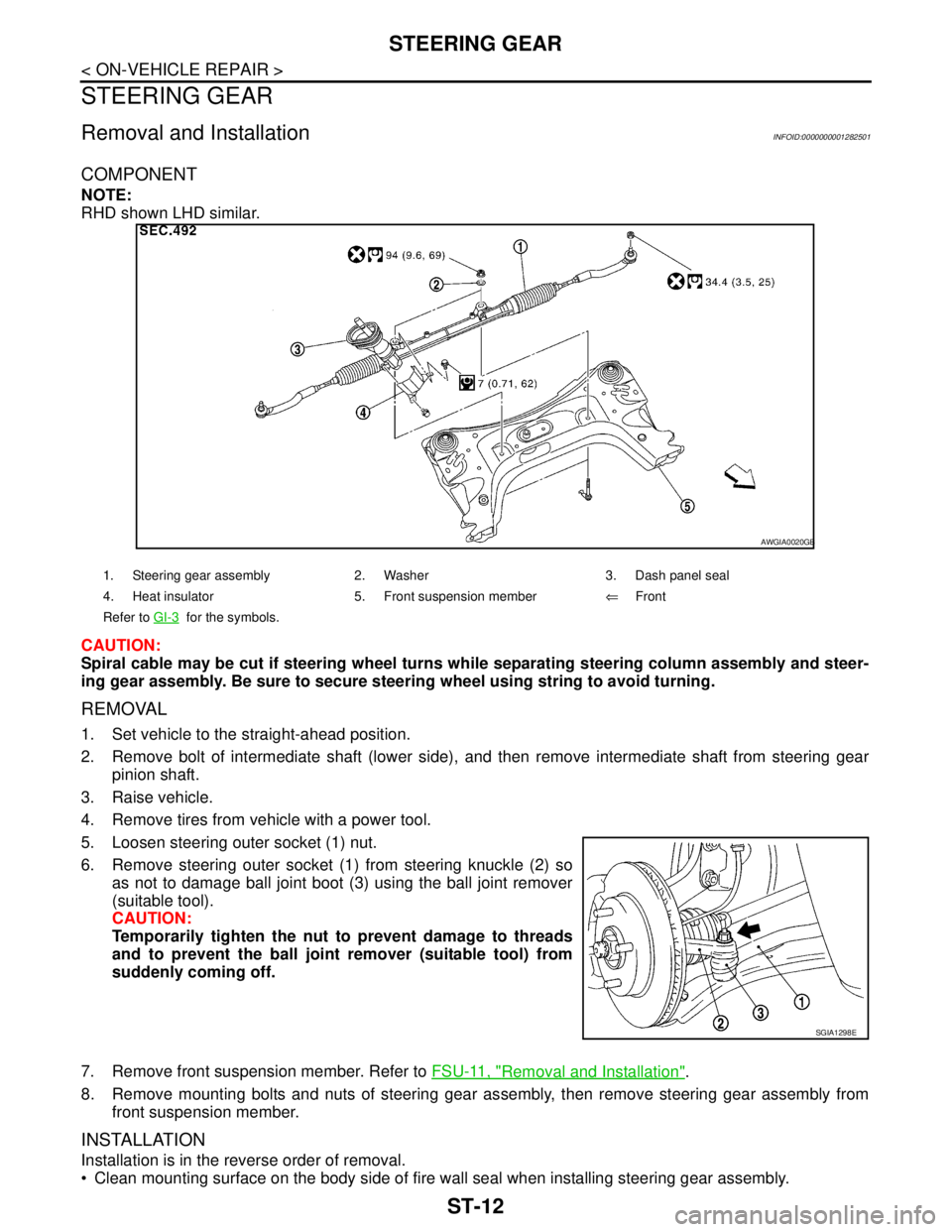
COMPONENT
NOTE:
RHD shown LHD similar.
CAUTION:
Spiral cable may be cut if steering wheel turns while separating steering column assembly and steer-
ing gear assembly. Be sure to secure steering wheel using string to avoid turning.
REMOVAL
1. Set vehicle to the straight-ahead position.
2. Remove bolt of intermediate shaft (lower side), and then remove intermediate shaft from steering gear
pinion shaft.
3. Raise vehicle.
4. Remove tires from vehicle with a power tool.
5. Loosen steering outer socket (1) nut.
6. Remove steering outer socket (1) from steering knuckle (2) so
as not to damage ball joint boot (3) using the ball joint remover
(suitable tool).
CAUTION:
Temporarily tighten the nut to prevent damage to threads
and to prevent the ball joint remover (suitable tool) from
suddenly coming off.
7. Remove front suspension member. Refer to FSU-11, "
Removal and Installation".
8. Remove mounting bolts and nuts of steering gear assembly, then remove steering gear assembly from
front suspension member.
INSTALLATION
Installation is in the reverse order of removal.
Clean mounting surface on the body side of fire wall seal when installing steering gear assembly.
1. Steering gear assembly 2. Washer 3. Dash panel seal
4. Heat insulator 5. Front suspension member⇐Front
Refer to GI-3
for the symbols.
AWGIA0020GB
SGIA1298E
Page 4924 of 5883
![NISSAN TIIDA 2007 Service Repair Manual STARTER MOTOR
STR-13
< ON-VEHICLE REPAIR >[HR16DE]
C
D
E
F
G
H
I
J
K
L
MA
STR
N
P O
ON-VEHICLE REPAIR
STARTER MOTOR
Removal and InstallationINFOID:0000000001689433
REMOVAL
1. Disconnect the battery ca NISSAN TIIDA 2007 Service Repair Manual STARTER MOTOR
STR-13
< ON-VEHICLE REPAIR >[HR16DE]
C
D
E
F
G
H
I
J
K
L
MA
STR
N
P O
ON-VEHICLE REPAIR
STARTER MOTOR
Removal and InstallationINFOID:0000000001689433
REMOVAL
1. Disconnect the battery ca](/manual-img/5/57395/w960_57395-4923.png)
STARTER MOTOR
STR-13
< ON-VEHICLE REPAIR >[HR16DE]
C
D
E
F
G
H
I
J
K
L
MA
STR
N
P O
ON-VEHICLE REPAIR
STARTER MOTOR
Removal and InstallationINFOID:0000000001689433
REMOVAL
1. Disconnect the battery cable from the negative terminal.
2. Remove “B” terminal nut and “B” terminal harness.
3. Remove “S” terminal nut and “S” terminal harness.
4. Remove starter motor bolts.
5. Remove starter motor upward from the vehicle.
INSTALLATION
Installation is in the reverse order of removal.
CAUTION:
Be sure to tighten “B” terminal nut carefully.
1. Cylinder block 2. “B” terminal harness 3. “S” terminal harness
4. Starter motor Vehicle front
PKIC0987E
Page 4935 of 5883
![NISSAN TIIDA 2007 Service Repair Manual STR-24
< ON-VEHICLE REPAIR >[MR18DE]
STARTER MOTOR
ON-VEHICLE REPAIR
STARTER MOTOR
Removal and InstallationINFOID:0000000001689442
REMOVAL
1. Disconnect the battery cable from the negative terminal.
2 NISSAN TIIDA 2007 Service Repair Manual STR-24
< ON-VEHICLE REPAIR >[MR18DE]
STARTER MOTOR
ON-VEHICLE REPAIR
STARTER MOTOR
Removal and InstallationINFOID:0000000001689442
REMOVAL
1. Disconnect the battery cable from the negative terminal.
2](/manual-img/5/57395/w960_57395-4934.png)
STR-24
< ON-VEHICLE REPAIR >[MR18DE]
STARTER MOTOR
ON-VEHICLE REPAIR
STARTER MOTOR
Removal and InstallationINFOID:0000000001689442
REMOVAL
1. Disconnect the battery cable from the negative terminal.
2. Disconnect the oil pressure switch connector.
3. Remove “B” terminal nut and “B” terminal harness.
4. Remove “S” terminal nut and “S” terminal harness.
5. Remove starter motor bolts.
6. Remove starter motor upward from the vehicle.
CAUTION:
Never damage oil pressure switch when removing starter motor.
INSTALLATION
Installation is in the reverse order of removal.
CAUTION:
Be sure to tighten “B” terminal nut carefully.
1. "S" terminal harness 2. "B" terminal harness 3. Starter motor
4. Cylinder block Engine front
WKIA5611E