2007 NISSAN TIIDA Rear suspension
[x] Cancel search: Rear suspensionPage 1 of 5883
MODEL C11 SERIES
2007 NISSAN EUROPE S.A.S.
All rights reserved. No part of this Electronic Service Manual may be reproduced or stored in a retrieval system, or transmitted in any form,
or by any means, electronic, mechanical, photocopying, recording or otherwise, without the prior written permission of Nissan Europe
S.A.S., Paris, France.
A GENERAL INFORMATION
B ENGINE
D TRANSMISSION& DRIVELINE
E SUSPENSION F BRAKES
G STEERING H RESTRAINTS
I VENTILATION, HEATER & AIR CONDITIONER
J BODY INTERIOR
K BODY EXTERIOR, DOOR, ROOF & VEHICLE SECURITY
L DRIVER CONTROLS
M ELECTRICAL & POWER CONTROL
N DRIVER INFORMATION & MULTIMEDIA
O CRUISE CONTROL P MAINTENANCEGI General Information
EM Engine Mechanical
LU Engine Lubrication System
CO Engine Cooling System
EC Engine Control System
FL Fuel System
EX Exhaust System
STR Starting System
ACC Accelerator Control System
CL Clutch
TM Transaxle & Transmission
FAX Front Axle
RAX Rear Axle
FSU Front Suspension
RSU Rear Suspension
WT Road Wheels & Tires
BR Brake System
PB Parking Brake System
BRC Brake Control System
ST Steering System
STC Steering Control System
SB Seat Belt
SR SRS Airbag
SRC SRS Airbag Control System
VTL Ventilation System
HA Heater & Air Conditioning System
HAC Heater & Air Conditioning Control System
INT Interior
IP Instrument Panel
SE Seat
DLK Door & Lock
SEC Security Control System
GW Glass & Window System
PWC Power Window Control System
RF Roof
EXT Exterior
MIR Mirrors
EXL Exterior Lighting System
INL Interior Lighting System
WW Wiper & Washer
DEF Defogger
HRN Horn
PWO Power Outlet
BCS Body Control System
LAN LAN System
PCS Power Control System
CHG Charging System
PG Power Supply, Ground & Circuit Elements
MWI Meter, Warning Lanp & Indicator
WCS Warning Chime System
AV Audio, Visual & Navigation System
CCS Cruise Control System Maintenance
MA Maintenance
QUICK REFERENCE INDEX
A
B
C
D
E
F
G
H
I
J
K
L
M
N
O
P
M
Publication Number:
SM7E00-1C11E0E
Page 316 of 5883
![NISSAN TIIDA 2007 Service Repair Manual WHEEL SENSORS
BRC-83
< REMOVAL AND INSTALLATION >[ABS]
C
D
E
G
H
I
J
K
L
MA
B
BRC
N
O
P
REMOVAL AND INSTALLATION
WHEEL SENSORS
Removal and InstallationINFOID:0000000001691408
REMOVAL
Be careful of the NISSAN TIIDA 2007 Service Repair Manual WHEEL SENSORS
BRC-83
< REMOVAL AND INSTALLATION >[ABS]
C
D
E
G
H
I
J
K
L
MA
B
BRC
N
O
P
REMOVAL AND INSTALLATION
WHEEL SENSORS
Removal and InstallationINFOID:0000000001691408
REMOVAL
Be careful of the](/manual-img/5/57395/w960_57395-315.png)
WHEEL SENSORS
BRC-83
< REMOVAL AND INSTALLATION >[ABS]
C
D
E
G
H
I
J
K
L
MA
B
BRC
N
O
P
REMOVAL AND INSTALLATION
WHEEL SENSORS
Removal and InstallationINFOID:0000000001691408
REMOVAL
Be careful of the following.
CAUTION:
When removing the sensor, do not rotate it if possible, and not forcibly pull the sensor harness.
Before removing front or rear wheel hub, remove wheel sensor to avoid sensor wiring damage.
INSTALLATION
Be certain to tighten bolts to the specified torque. Be careful of the following:
Check the inside of the sensor mounting hole for foreign material, the rotor surface for iron chips and other
foreign material, and if anything is non-standard, clean it before installation, or replace it.
When installing the front sensor, completely push in the strut bracket and body bracket rubber grommets
until they lock so that the sensor harness does not become twisted. In addition, there should be no twists in
the harness when installed. Install the harness so that the painted part faces the outside of the vehicle.
When installing the rear sensor, completely push in the rubber bracket of the suspension arm bracket and
lock the marking area of the side member harness mount so that the sensor harness will not be twisted. In
addition, there should be no twists in the harness when installed.
MFIB9029E
Page 415 of 5883
![NISSAN TIIDA 2007 Service Repair Manual BRC-182
< REMOVAL AND INSTALLATION >[ESP/TCS/ABS]
WHEEL SENSORS
REMOVAL AND INSTALLATION
WHEEL SENSORS
Removal and InstallationINFOID:0000000001691451
REMOVAL
Be careful of the following.
CAUTION:
W NISSAN TIIDA 2007 Service Repair Manual BRC-182
< REMOVAL AND INSTALLATION >[ESP/TCS/ABS]
WHEEL SENSORS
REMOVAL AND INSTALLATION
WHEEL SENSORS
Removal and InstallationINFOID:0000000001691451
REMOVAL
Be careful of the following.
CAUTION:
W](/manual-img/5/57395/w960_57395-414.png)
BRC-182
< REMOVAL AND INSTALLATION >[ESP/TCS/ABS]
WHEEL SENSORS
REMOVAL AND INSTALLATION
WHEEL SENSORS
Removal and InstallationINFOID:0000000001691451
REMOVAL
Be careful of the following.
CAUTION:
When removing the sensor, do not rotate it if possible, and not forcibly pull the sensor harness.
Before removing front or rear wheel hub, remove wheel sensor to avoid sensor wiring damage.
INSTALLATION
Be certain to tighten bolts to the specified torque. Be careful of the following: Check the inside of the sensor mounting hole for foreign material, the rotor surface for iron chips and other
foreign material, and if anything is non-standard, clean it before installation, or replace it.
When installing the front sensor, completely push in the strut bracket and body bracket rubber grommets
until they lock so that the sensor harness does not become twisted. In addition, there should be no twists in
the harness when installed. Install the harness so that the painted part faces the outside of the vehicle.
When installing the rear sensor, completely push in the rubber bracket of the suspension arm bracket and
lock the marking area of the side member harness mount so that the sensor harness will not be twisted. In
addition, there should be no twists in the harness when installed.
MFIB9030E
Page 3182 of 5883
FSU-6
< ON-VEHICLE MAINTENANCE >
FRONT SUSPENSION ASSEMBLY
ON-VEHICLE MAINTENANCE
FRONT SUSPENSION ASSEMBLY
On-Vehicle Inspection and ServiceINFOID:0000000001716890
Make sure the mounting conditions (looseness, back lash) of each component and component conditions
(wear, damage) are normal.
INSPECTION OF LOWER BALL JOINT END PLAY
1. Set front wheels in a straight-ahead position. Do not depress brake pedal.
2. Place an iron bar or similar tool between transverse link and steering knuckle.
3. Measure axial end play by prying it up and down.
CAUTION:
Be careful not to damage ball joint boot. Do not damage the installation position by applying
excessive force.
STRUT INSPECTION
Check for oil leakage, damage and replace as necessary.
Wheel Alignment InspectionINFOID:0000000001716891
PRELIMINARY INSPECTION
WARNING:
Always adjust the alignment with the vehicle on a flat surface.
NOTE:
If alignment is out of specification, inspect and replace any damaged or worn rear suspension parts before
making any adjustments.
1. Check and adjust the wheel alignment with the vehicle under unladen conditions. “Unladen conditions”
means that the fuel, coolant, and lubricant are full; and that the spare tire, jack, hand tools and mats are in
their designated positions.
2. Check the tires for incorrect air pressure and excessive wear.
3. Check the wheels for run out and damage. Refer to WT-5, "
Inspection" .
4. Check the wheel bearing axial end play. Refer to FA X - 5 , "
On-Vehicle Inspection and Service" .
5. Check the shock absorbers for leaks or damage.
6. Check each mounting point of the suspension components for any excessive looseness or damage.
7. Check each link, arm, and the suspension member for any damage.
8. Check the vehicle height. Refer to FSU-18, "
Wheelarch Height (Unladen*)" .
GENERAL INFORMATION AND RECOMMENDATIONS
1. A Four-Wheel Thrust Alignment should be performed.
This type of alignment is recommended for any NISSAN vehicle.
The four-wheel “thrust” process helps ensure that the vehicle is properly aligned and the steering wheel
is centered.
The alignment machine itself should be capable of accepting any NISSAN vehicle.
The alignment machine should be checked to ensure that it is level.
2. Make sure the alignment machine is properly calibrated.
Your alignment machine should be regularly calibrated in order to give correct information.
Check with the manufacturer of your specific alignment machine for their recommended Service/Cali-
bration Schedule.
THE ALIGNMENT PROCESS
IMPORTANT: Use only the alignment specifications listed in this Service Manual. Refer to FSU-17, "Wheel
Alignment (Unladen*)" .
1. When displaying the alignment settings, many alignment machines use “indicators”: (Green/red, plus or
minus, Go/No Go). Do NOT use these indicators. Axial end play : 0 mm (0 in)
Page 3183 of 5883
FRONT SUSPENSION ASSEMBLY
FSU-7
< ON-VEHICLE MAINTENANCE >
C
D
F
G
H
I
J
K
L
MA
B
FSU
N
O
P
The alignment specifications programmed into your alignment machine that operate these indicators
may not be correct.
This may result in an ERROR.
2. Some newer alignment machines are equipped with an optional “Rolling Compensation” method to “com-
pensate” the sensors (alignment targets or head units). Do NOT use this “Rolling Compensation”
method.
Use the “Jacking Compensation” method. After installing the alignment targets or head units, raise the
vehicle and rotate the wheels 1/2 turn both ways.
See Instructions in the alignment machine you are using for more information.
CAMBER, CASTER AND KINGPIN INCLINATION ANGLES INSPECTION
Camber, caster, kingpin inclination angles cannot be adjusted.
Before inspection, mount front wheels onto turning radius gauge. Mount rear wheels onto a stand that has
same height so vehicle will remain horizontal.
Using a CCK Gauge
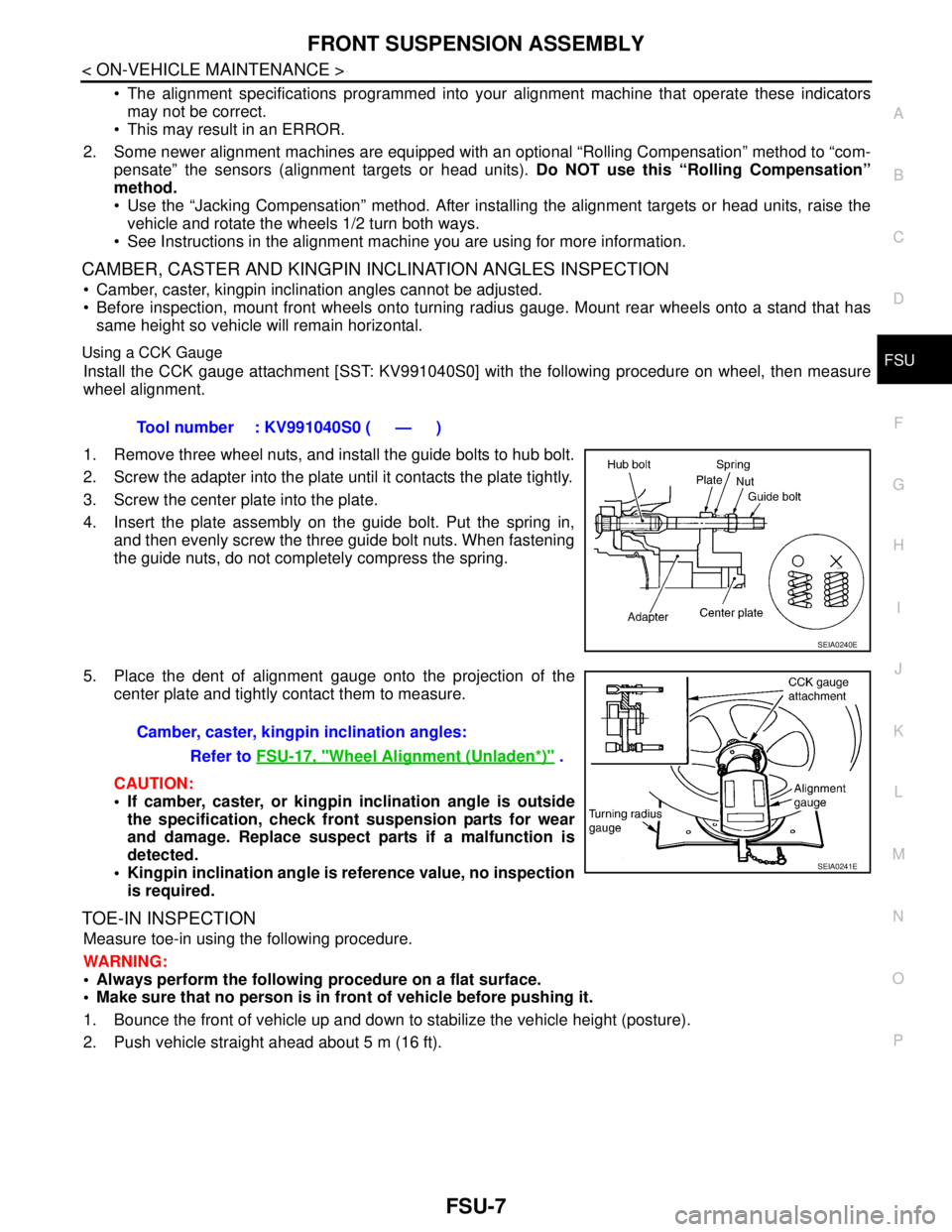
Install the CCK gauge attachment [SST: KV991040S0] with the following procedure on wheel, then measure
wheel alignment.
1. Remove three wheel nuts, and install the guide bolts to hub bolt.
2. Screw the adapter into the plate until it contacts the plate tightly.
3. Screw the center plate into the plate.
4. Insert the plate assembly on the guide bolt. Put the spring in,
and then evenly screw the three guide bolt nuts. When fastening
the guide nuts, do not completely compress the spring.
5. Place the dent of alignment gauge onto the projection of the
center plate and tightly contact them to measure.
CAUTION:
If camber, caster, or kingpin inclination angle is outside
the specification, check front suspension parts for wear
and damage. Replace suspect parts if a malfunction is
detected.
Kingpin inclination angle is reference value, no inspection
is required.
TOE-IN INSPECTION
Measure toe-in using the following procedure.
WARNING:
Always perform the following procedure on a flat surface.
Make sure that no person is in front of vehicle before pushing it.
1. Bounce the front of vehicle up and down to stabilize the vehicle height (posture).
2. Push vehicle straight ahead about 5 m (16 ft).Tool number : KV991040S0 ( — )
SEIA0240E
Camber, caster, kingpin inclination angles:
Refer to FSU-17, "
Wheel Alignment (Unladen*)" .
SEIA0241E
Page 3184 of 5883
FSU-8
< ON-VEHICLE MAINTENANCE >
FRONT SUSPENSION ASSEMBLY
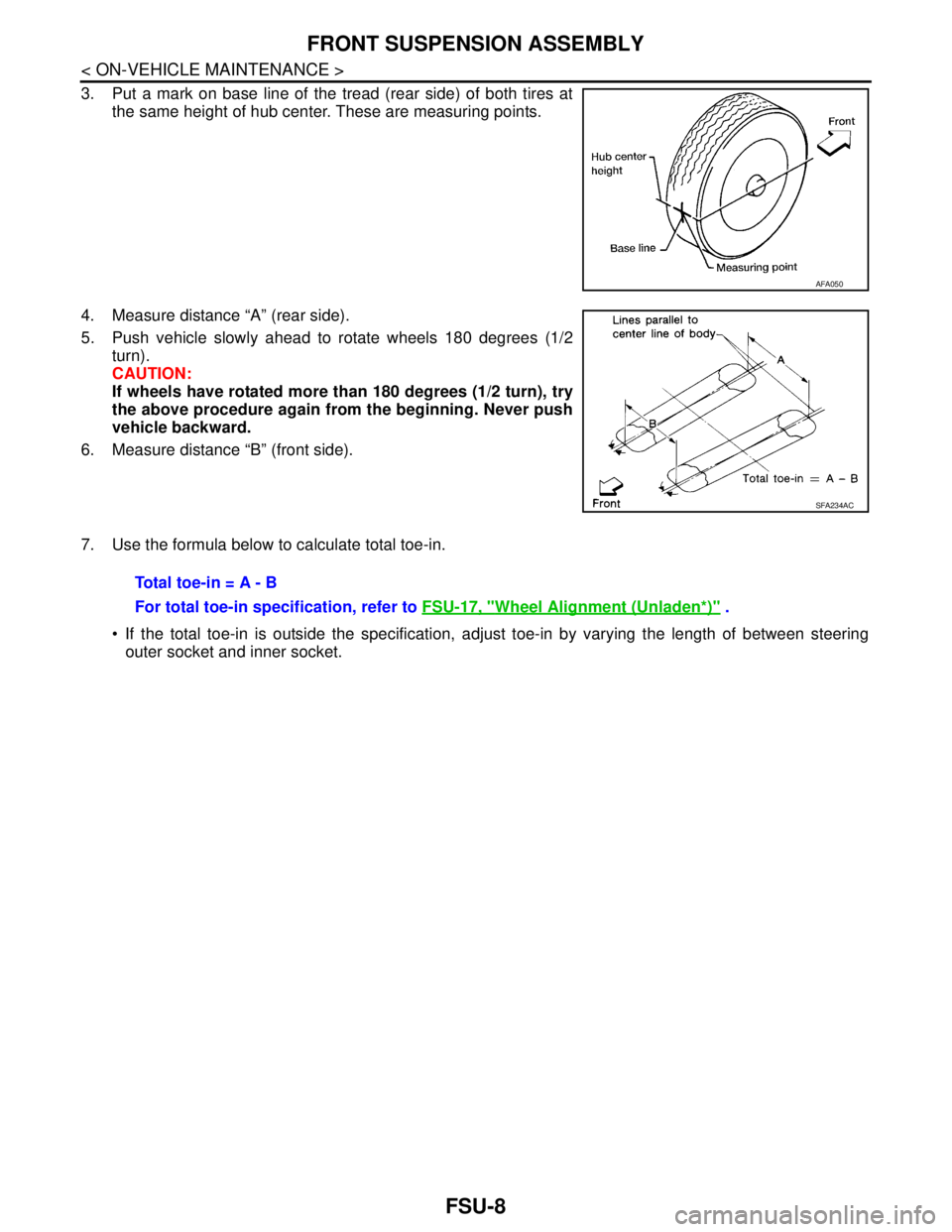
3. Put a mark on base line of the tread (rear side) of both tires at
the same height of hub center. These are measuring points.
4. Measure distance “A” (rear side).
5. Push vehicle slowly ahead to rotate wheels 180 degrees (1/2
turn).
CAUTION:
If wheels have rotated more than 180 degrees (1/2 turn), try
the above procedure again from the beginning. Never push
vehicle backward.
6. Measure distance “B” (front side).
7. Use the formula below to calculate total toe-in.
If the total toe-in is outside the specification, adjust toe-in by varying the length of between steering
outer socket and inner socket.
AFA050
SFA234AC
Total toe-in = A - B
For total toe-in specification, refer to FSU-17, "
Wheel Alignment (Unladen*)" .
Page 3187 of 5883
FRONT SUSPENSION ASSEMBLY
FSU-11
< REMOVAL AND INSTALLATION >
C
D
F
G
H
I
J
K
L
MA
B
FSU
N
O
P
REMOVAL AND INSTALLATION
FRONT SUSPENSION ASSEMBLY
Removal and InstallationINFOID:0000000001716901
REMOVAL
1. Separate intermediate shaft from steering gear pinion shaft. Refer to ST-9, "Removal and Installation".
2. Remove front tires from vehicle using a power tool.
3. Remove wheel sensor from steering knuckle. Refer to BRC-182, "
Removal and Installation".
CAUTION:
Do not pull on wheel sensor harness.
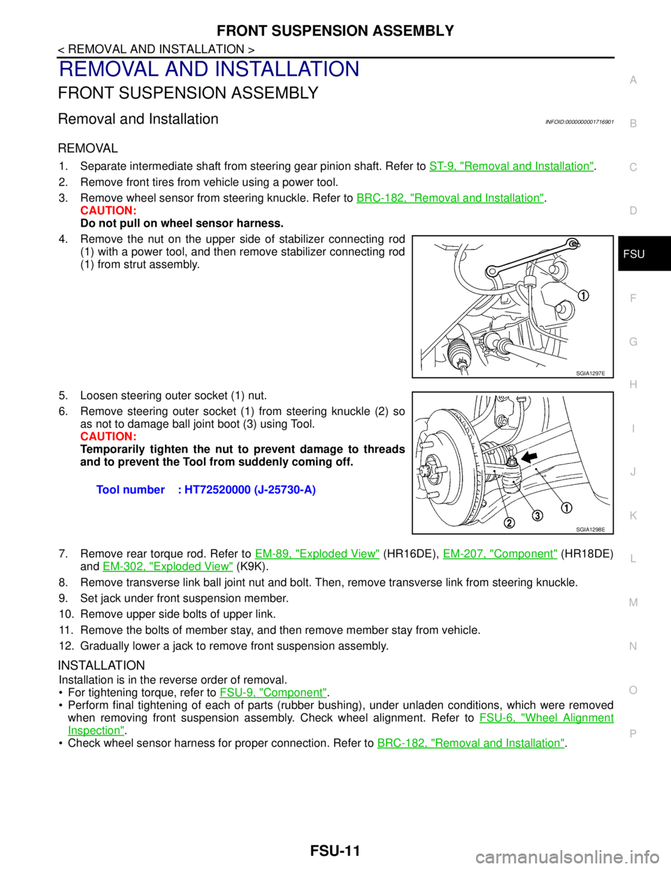
4. Remove the nut on the upper side of stabilizer connecting rod
(1) with a power tool, and then remove stabilizer connecting rod
(1) from strut assembly.
5. Loosen steering outer socket (1) nut.
6. Remove steering outer socket (1) from steering knuckle (2) so
as not to damage ball joint boot (3) using Tool.
CAUTION:
Temporarily tighten the nut to prevent damage to threads
and to prevent the Tool from suddenly coming off.
7. Remove rear torque rod. Refer to EM-89, "
Exploded View" (HR16DE), EM-207, "Component" (HR18DE)
and EM-302, "
Exploded View" (K9K).
8. Remove transverse link ball joint nut and bolt. Then, remove transverse link from steering knuckle.
9. Set jack under front suspension member.
10. Remove upper side bolts of upper link.
11. Remove the bolts of member stay, and then remove member stay from vehicle.
12. Gradually lower a jack to remove front suspension assembly.
INSTALLATION
Installation is in the reverse order of removal.
For tightening torque, refer to FSU-9, "
Component".
Perform final tightening of each of parts (rubber bushing), under unladen conditions, which were removed
when removing front suspension assembly. Check wheel alignment. Refer to FSU-6, "
Wheel Alignment
Inspection".
Check wheel sensor harness for proper connection. Refer to BRC-182, "
Removal and Installation".
SGIA1297E
Tool number : HT72520000 (J-25730-A)
SGIA1298E
Page 3190 of 5883
FSU-14
< REMOVAL AND INSTALLATION >
STABILIZER BAR
STABILIZER BAR
Removal and InstallationINFOID:0000000001716884
REMOVAL
1. Separate intermediate shaft from steering gear pinion shaft. Refer to ST-9, "Removal and Installation" .
2. Remove front tires using power tool.
3. Remove the nut on the lower side of stabilizer connecting rod using power tool, and then remove stabilizer
connecting rod from stabilizer bar.
4. If necessary remove stabilize connecting rod upper nut using power tool. Separate stabilizer connecting
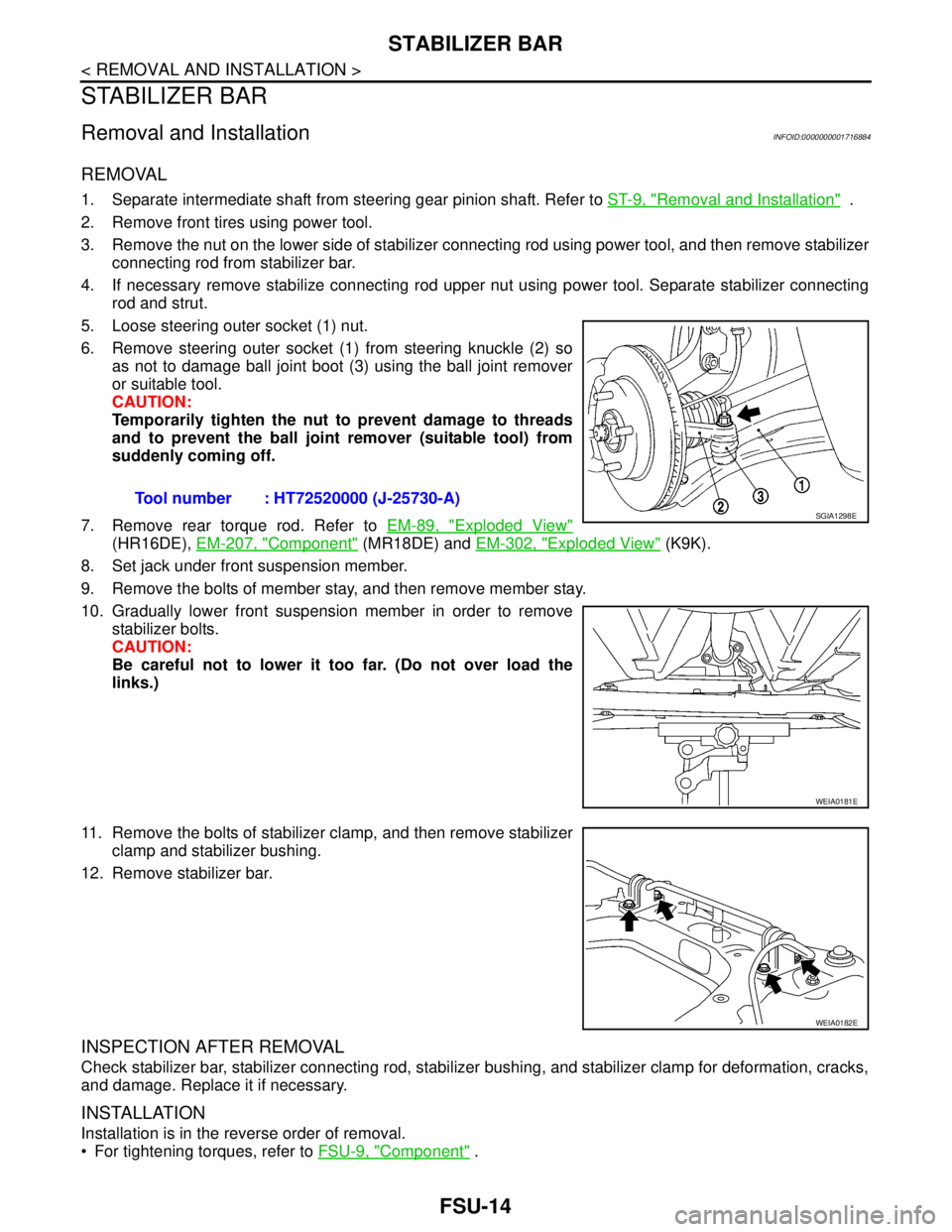
rod and strut.
5. Loose steering outer socket (1) nut.
6. Remove steering outer socket (1) from steering knuckle (2) so
as not to damage ball joint boot (3) using the ball joint remover
or suitable tool.
CAUTION:
Temporarily tighten the nut to prevent damage to threads
and to prevent the ball joint remover (suitable tool) from
suddenly coming off.
7. Remove rear torque rod. Refer to EM-89, "
Exploded View"
(HR16DE), EM-207, "Component" (MR18DE) and EM-302, "Exploded View" (K9K).
8. Set jack under front suspension member.
9. Remove the bolts of member stay, and then remove member stay.
10. Gradually lower front suspension member in order to remove
stabilizer bolts.
CAUTION:
Be careful not to lower it too far. (Do not over load the
links.)
11. Remove the bolts of stabilizer clamp, and then remove stabilizer
clamp and stabilizer bushing.
12. Remove stabilizer bar.
INSPECTION AFTER REMOVAL
Check stabilizer bar, stabilizer connecting rod, stabilizer bushing, and stabilizer clamp for deformation, cracks,
and damage. Replace it if necessary.
INSTALLATION
Installation is in the reverse order of removal.
For tightening torques, refer to FSU-9, "
Component" . Tool number : HT72520000 (J-25730-A)
SGIA1298E
WEIA0181E
WEIA0182E