Page 3242 of 5883
GI-48
< PRECAUTION >
LIFTING POINT
LIFTING POINT
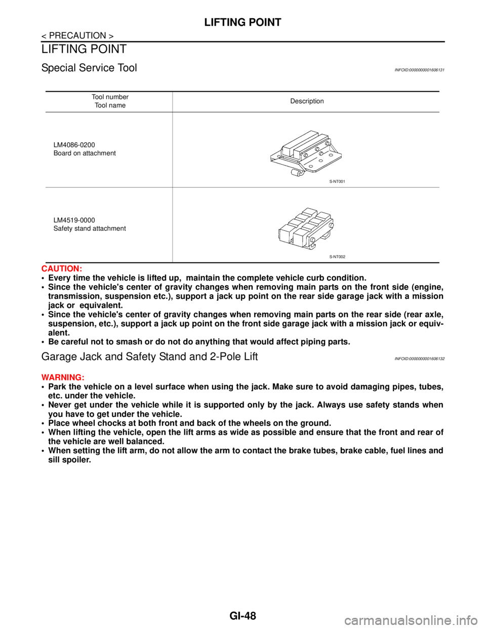
Special Service ToolINFOID:0000000001606131
CAUTION:
Every time the vehicle is lifted up, maintain the complete vehicle curb condition.
Since the vehicle's center of gravity changes when removing main parts on the front side (engine,
transmission, suspension etc.), support a jack up point on the rear side garage jack with a mission
jack or equivalent.
Since the vehicle's center of gravity changes when removing main parts on the rear side (rear axle,
suspension, etc.), support a jack up point on the front side garage jack with a mission jack or equiv-
alent.
Be careful not to smash or do not do anything that would affect piping parts.
Garage Jack and Safety Stand and 2-Pole LiftINFOID:0000000001606132
WARNING:
Park the vehicle on a level surface when using the jack. Make sure to avoid damaging pipes, tubes,
etc. under the vehicle.
Never get under the vehicle while it is supported only by the jack. Always use safety stands when
you have to get under the vehicle.
Place wheel chocks at both front and back of the wheels on the ground.
When lifting the vehicle, open the lift arms as wide as possible and ensure that the front and rear of
the vehicle are well balanced.
When setting the lift arm, do not allow the arm to contact the brake tubes, brake cable, fuel lines and
sill spoiler.
Tool number
Tool nameDescription
LM4086-0200
Board on attachment
LM4519-0000
Safety stand attachment
S-NT001
S-NT002
Page 3244 of 5883
GI-50
< PRECAUTION >
TOW TRUCK TOWING
TOW TRUCK TOWING
Tow Truck TowingINFOID:0000000001606140
CAUTION:
All applicable local laws regarding the towing operation must be obeyed.
It is necessary to use proper towing equipment to avoid possible damage to the vehicle during tow-
ing operation. Towing is in accordance with Towing Procedure Manual at dealer.
Always attach safety chains before towing.
When towing, make sure that the transmission, steering system and power train are in good order. If
any unit is damaged, dollies must be used.
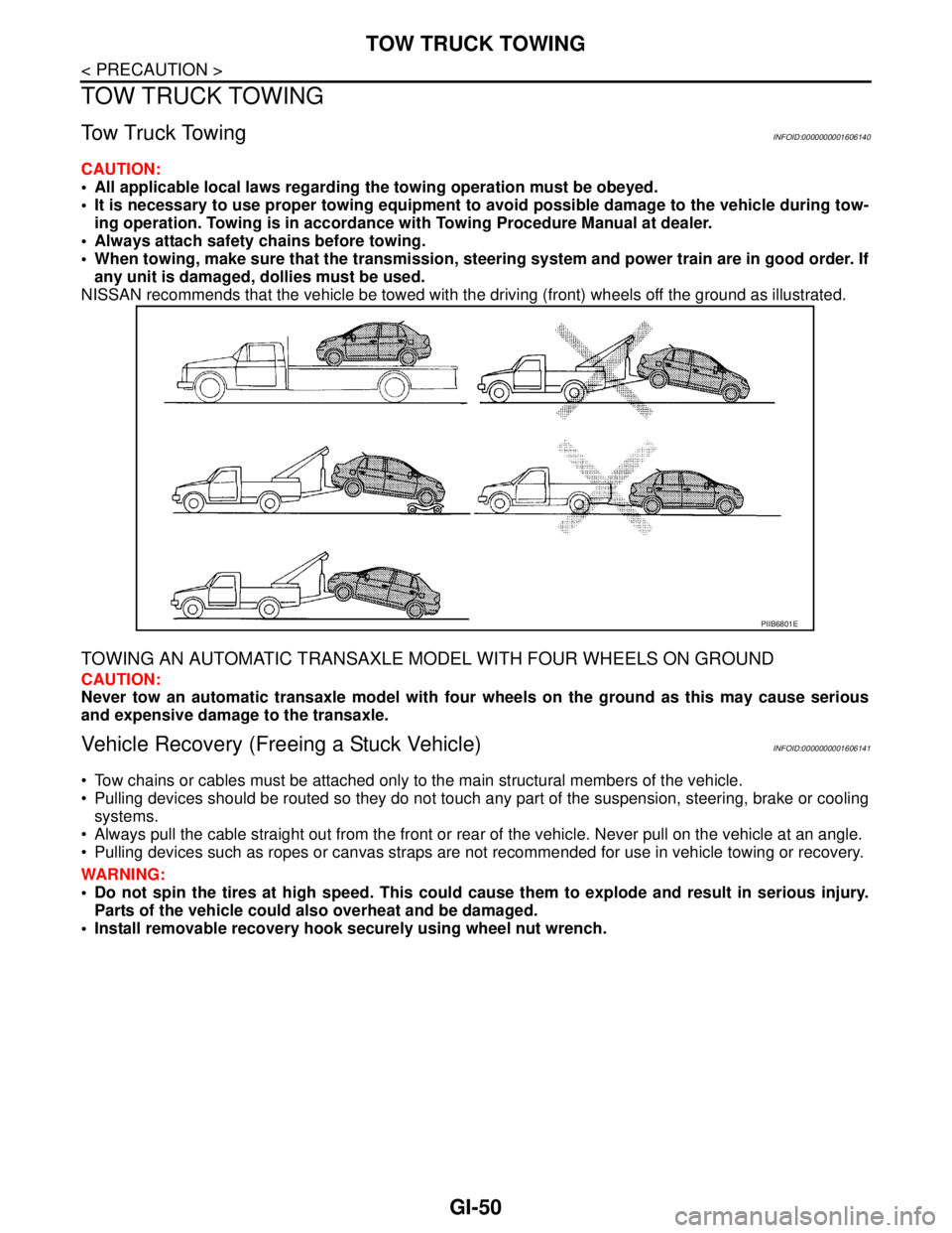
NISSAN recommends that the vehicle be towed with the driving (front) wheels off the ground as illustrated.
TOWING AN AUTOMATIC TRANSAXLE MODEL WITH FOUR WHEELS ON GROUND
CAUTION:
Never tow an automatic transaxle model with four wheels on the ground as this may cause serious
and expensive damage to the transaxle.
Vehicle Recovery (Freeing a Stuck Vehicle)INFOID:0000000001606141
Tow chains or cables must be attached only to the main structural members of the vehicle.
Pulling devices should be routed so they do not touch any part of the suspension, steering, brake or cooling
systems.
Always pull the cable straight out from the front or rear of the vehicle. Never pull on the vehicle at an angle.
Pulling devices such as ropes or canvas straps are not recommended for use in vehicle towing or recovery.
WARNING:
Do not spin the tires at high speed. This could cause them to explode and result in serious injury.
Parts of the vehicle could also overheat and be damaged.
Install removable recovery hook securely using wheel nut wrench.
PIIB6801E
Page 4296 of 5883
MA-56
< ON-VEHICLE MAINTENANCE >
CHASSIS AND BODY MAINTENANCE
Check the brake pads for wear or damage. Refer to BR-24,
"Removal and Installation of Brake Pad" .
Axle and Suspension PartsINFOID:0000000001730909
Check front and rear axle and suspension parts for excessive play,
cracks, wear or other damage.
Shake each wheel to check for excessive play.
Check wheel bearings for smooth operation.
Check axle and suspension nuts and bolts for looseness.
Check strut (shock absorber) for oil leakage or other damage.
Check suspension ball joint for grease leakage and ball joint dust
cover for cracks or other damage.
Drive ShaftINFOID:0000000001730910
Check boot and drive shaft for cracks, wear, damage and grease
leakage.
BRA0010D
SMA525A
SFA392B
SDIA1190J
Page 4529 of 5883
RAX-2
< SYMPTOM DIAGNOSIS >
NOISE, VIBRATION AND HARSHNESS (NVH) TROUBLESHOOTING
SYMPTOM DIAGNOSIS
NOISE, VIBRATION AND HARSHNESS (NVH) TROUBLESHOOTING
NVH Troubleshooting ChartINFOID:0000000001724593
Use chart below to help you find the cause of the symptom. If necessary, repair or replace these parts.
×: ApplicableReference page
RAX-6—
RAX-5
RSU-2, "
NVH Troubleshooting Chart
"
WT-4, "
NVH Troubleshooting Chart
"
WT-4, "
NVH Troubleshooting Chart
"
BR-5, "
NVH Troubleshooting Chart
"
ST-5, "
NVH Troubleshooting Chart
"
Possible cause and SUSPECTED PARTS
Improper installation, looseness
Parts interference
Wheel bearing damage
REAR AXLE AND REAR SUSPENSION
TIRES
ROAD WHEEL
BRAKES
STEERING
Symptom REAR AXLENoise×× ×××××
Shake×× ×××××
Vibration×× ×× ×
Shimmy×× ×××××
Judder× ×××××
Poor quality ride or handling××××××
Page 4532 of 5883
WHEEL HUB
RAX-5
< ON-VEHICLE MAINTENANCE >
C
E
F
G
H
I
J
K
L
MA
B
RAX
N
O
P
ON-VEHICLE MAINTENANCE
WHEEL HUB
On-Vehicle Inspection and ServiceINFOID:0000000001724590
Check the axle and suspension parts for excessive play, wear, or damage.
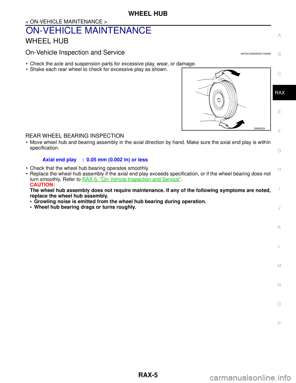
Shake each rear wheel to check for excessive play as shown.
REAR WHEEL BEARING INSPECTION
Move wheel hub and bearing assembly in the axial direction by hand. Make sure the axial end play is within
specification.
Check that the wheel hub bearing operates smoothly.
Replace the wheel hub assembly if the axial end play exceeds specification, or if the wheel bearing does not
turn smoothly. Refer to RAX-5, "
On-Vehicle Inspection and Service".
CAUTION:
The wheel hub assembly does not require maintenance. If any of the following symptoms are noted,
replace the wheel hub assembly.
Growling noise is emitted from the wheel hub bearing during operation.
Wheel hub bearing drags or turns roughly.
SMA525A
Axial end play : 0.05 mm (0.002 in) or less
Page 4533 of 5883
RAX-6
< ON-VEHICLE REPAIR >
WHEEL HUB
ON-VEHICLE REPAIR
WHEEL HUB
Removal and InstallationINFOID:0000000001724589
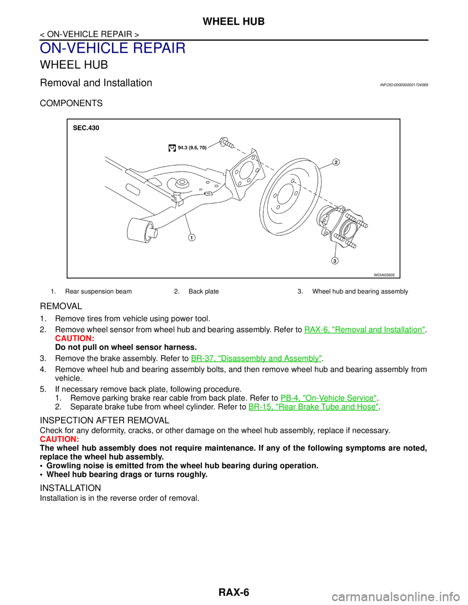
COMPONENTS
REMOVAL
1. Remove tires from vehicle using power tool.
2. Remove wheel sensor from wheel hub and bearing assembly. Refer to RAX-6, "
Removal and Installation".
CAUTION:
Do not pull on wheel sensor harness.
3. Remove the brake assembly. Refer to BR-37, "
Disassembly and Assembly".
4. Remove wheel hub and bearing assembly bolts, and then remove wheel hub and bearing assembly from
vehicle.
5. If necessary remove back plate, following procedure.
1. Remove parking brake rear cable from back plate. Refer to PB-4, "
On-Vehicle Service".
2. Separate brake tube from wheel cylinder. Refer to BR-15, "
Rear Brake Tube and Hose".
INSPECTION AFTER REMOVAL
Check for any deformity, cracks, or other damage on the wheel hub assembly, replace if necessary.
CAUTION:
The wheel hub assembly does not require maintenance. If any of the following symptoms are noted,
replace the wheel hub assembly.
Growling noise is emitted from the wheel hub bearing during operation.
Wheel hub bearing drags or turns roughly.
INSTALLATION
Installation is in the reverse order of removal.
1. Rear suspension beam 2. Back plate 3. Wheel hub and bearing assembly
WDIA0360E
Page 4573 of 5883
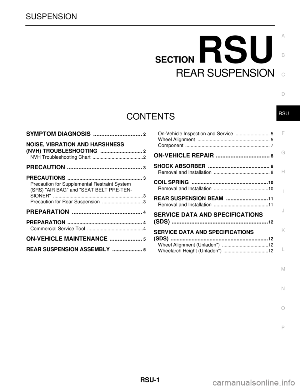
RSU-1
SUSPENSION
C
D
F
G
H
I
J
K
L
M
SECTION RSU
A
B
RSU
N
O
PCONTENTS
REAR SUSPENSION
SYMPTOM DIAGNOSIS ...............................2
NOISE, VIBRATION AND HARSHNESS
(NVH) TROUBLESHOOTING .............................
2
NVH Troubleshooting Chart ......................................2
PRECAUTION ...............................................3
PRECAUTIONS ...................................................3
Precaution for Supplemental Restraint System
(SRS) "AIR BAG" and "SEAT BELT PRE-TEN-
SIONER" ...................................................................
3
Precaution for Rear Suspension ...............................3
PREPARATION ............................................4
PREPARATION ...................................................4
Commercial Service Tool ..........................................4
ON-VEHICLE MAINTENANCE .....................5
REAR SUSPENSION ASSEMBLY .....................5
On-Vehicle Inspection and Service ..........................5
Wheel Alignment ......................................................5
Component ...............................................................7
ON-VEHICLE REPAIR ..................................8
SHOCK ABSORBER .........................................8
Removal and Installation ..........................................8
COIL SPRING ...................................................10
Removal and Installation .........................................10
REAR SUSPENSION BEAM ............................11
Removal and Installation .........................................11
SERVICE DATA AND SPECIFICATIONS
(SDS) ............................................................
12
SERVICE DATA AND SPECIFICATIONS
(SDS) .................................................................
12
Wheel Alignment (Unladen*) ...................................12
Wheelarch Height (Unladen*) ..................................12
Page 4574 of 5883
RSU-2
< SYMPTOM DIAGNOSIS >
NOISE, VIBRATION AND HARSHNESS (NVH) TROUBLESHOOTING
SYMPTOM DIAGNOSIS
NOISE, VIBRATION AND HARSHNESS (NVH) TROUBLESHOOTING
NVH Troubleshooting ChartINFOID:0000000001724586
Use chart below to help you find the cause of the symptom. If necessary, repair or replace these parts.
×: ApplicableReference page
RSU-7RSU-8RSU-8RSU-8RSU-10RSU-7RSU-5
RAX-2, "
NVH Troubleshooting Chart
"
WT-4, "
NVH Troubleshooting Chart
"
WT-4, "
NVH Troubleshooting Chart
"
BR-5, "
NVH Troubleshooting Chart
"
ST-5, "
NVH Troubleshooting Chart
"
Possible cause and SUSPECTED PARTS
Improper installation, looseness
Shock absorber deformation, damage or deflection
Bushing or mounting deterioration
Parts interference
Spring fatigue
Suspension looseness
Incorrect wheel alignment
REAR AXLE
TIRES
ROAD WHEEL
BRAKES
STEERING
SymptomNoise×××××× ×××××
Shake×××× × ×××××
Vibration××××× ×× ×
Shimmy×××× ××××××
Judder ××× ×××××
Poor quality ride or handling××××× ××××