2007 NISSAN TIIDA reverse
[x] Cancel search: reversePage 4542 of 5883
RF-8
< FUNCTION DIAGNOSIS >
SUNROOF SYSTEM
FUNCTION DIAGNOSIS
SUNROOF SYSTEM
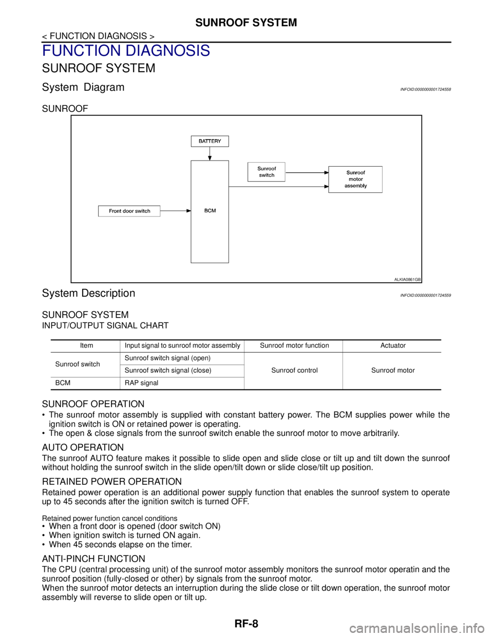
System DiagramINFOID:0000000001724558
SUNROOF
System DescriptionINFOID:0000000001724559
SUNROOF SYSTEM
INPUT/OUTPUT SIGNAL CHART
SUNROOF OPERATION
The sunroof motor assembly is supplied with constant battery power. The BCM supplies power while the
ignition switch is ON or retained power is operating.
The open & close signals from the sunroof switch enable the sunroof motor to move arbitrarily.
AUTO OPERATION
The sunroof AUTO feature makes it possible to slide open and slide close or tilt up and tilt down the sunroof
without holding the sunroof switch in the slide open/tilt down or slide close/tilt up position.
RETAINED POWER OPERATION
Retained power operation is an additional power supply function that enables the sunroof system to operate
up to 45 seconds after the ignition switch is turned OFF.
Retained power function cancel conditions
When a front door is opened (door switch ON)
When ignition switch is turned ON again.
When 45 seconds elapse on the timer.
ANTI-PINCH FUNCTION
The CPU (central processing unit) of the sunroof motor assembly monitors the sunroof motor operatin and the
sunroof position (fully-closed or other) by signals from the sunroof motor.
When the sunroof motor detects an interruption during the slide close or tilt down operation, the sunroof motor
assembly will reverse to slide open or tilt up.
ALKIA0861GB
Item Input signal to sunroof motor assembly Sunroof motor function Actuator
Sunroof switchSunroof switch signal (open)
Sunroof control Sunroof motor Sunroof switch signal (close)
BCM RAP signal
Page 4571 of 5883
SUNROOF SYSTEM
RF-37
< ON-VEHICLE REPAIR >
C
D
E
F
G
H
I
J
L
MA
B
RF
N
O
P
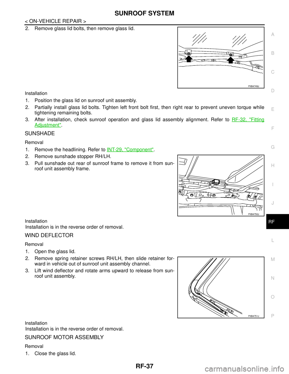
2. Remove glass lid bolts, then remove glass lid.
Installation
1. Position the glass lid on sunroof unit assembly.
2. Partially install glass lid bolts. Tighten left front bolt first, then right rear to prevent uneven torque while
tightening remaining bolts.
3. After installation, check sunroof operation and glass lid assembly alignment. Refer to RF-32, "
Fitting
Adjustment".
SUNSHADE
Removal
1. Remove the headlining. Refer to INT-29, "Component".
2. Remove sunshade stopper RH/LH.
3. Pull sunshade out rear of sunroof frame to remove it from sun-
roof unit assembly frame.
Installation
Installation is in the reverse order of removal.
WIND DEFLECTOR
Removal
1. Open the glass lid.
2. Remove spring retainer screws RH/LH, then slide retainer for-
ward in vehicle out of sunroof unit assembly channel.
3. Lift wind deflector and rotate arms upward to release from sun-
roof unit assembly.
Installation
Installation is in the reverse order of removal.
SUNROOF MOTOR ASSEMBLY
Removal
1. Close the glass lid.
PIIB4749J
PIIB4750J
PIIB4751J
Page 4572 of 5883
RF-38
< ON-VEHICLE REPAIR >
SUNROOF SYSTEM
2. Remove headlining. Refer to INT-29, "Component".
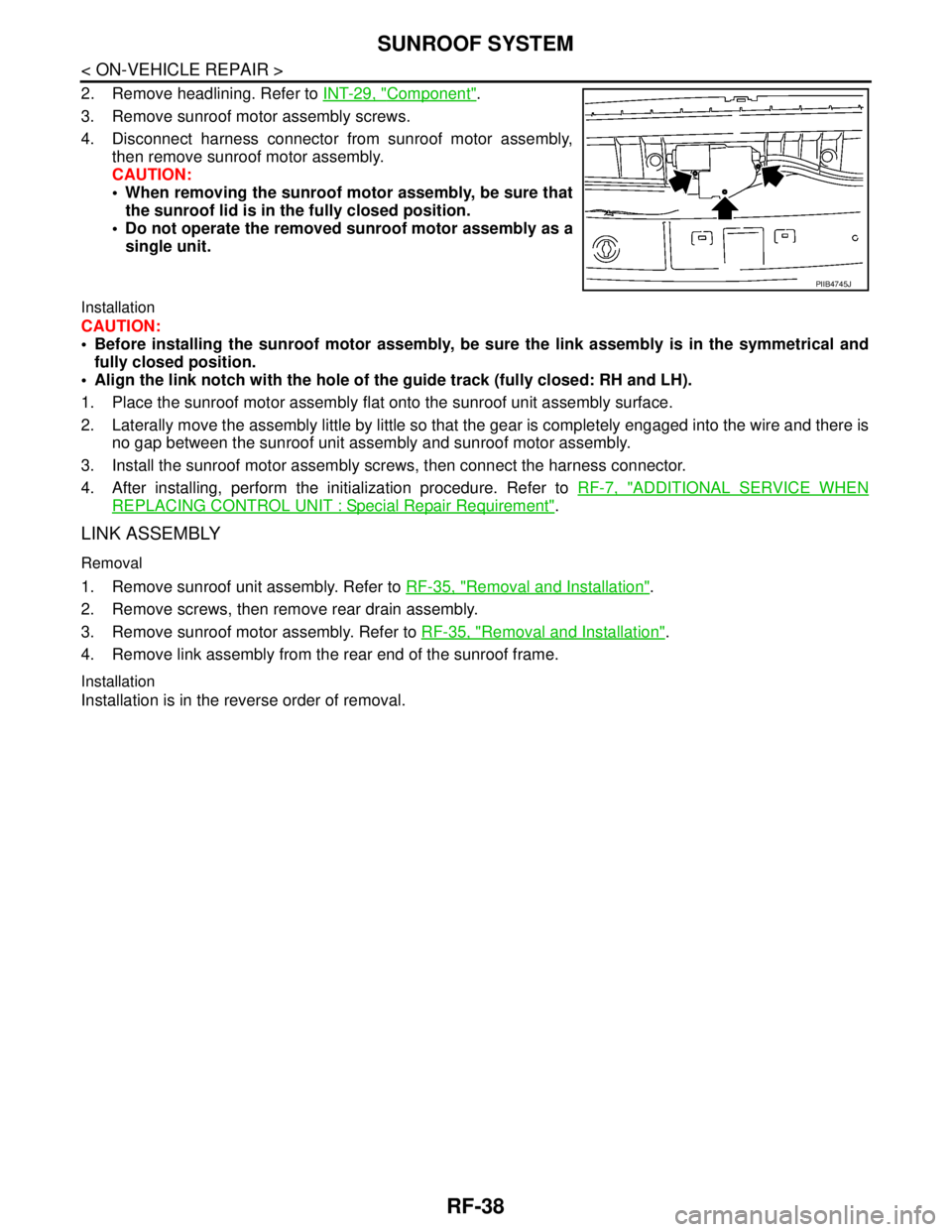
3. Remove sunroof motor assembly screws.
4. Disconnect harness connector from sunroof motor assembly,
then remove sunroof motor assembly.
CAUTION:
When removing the sunroof motor assembly, be sure that
the sunroof lid is in the fully closed position.
Do not operate the removed sunroof motor assembly as a
single unit.
Installation
CAUTION:
Before installing the sunroof motor assembly, be sure the link assembly is in the symmetrical and
fully closed position.
Align the link notch with the hole of the guide track (fully closed: RH and LH).
1. Place the sunroof motor assembly flat onto the sunroof unit assembly surface.
2. Laterally move the assembly little by little so that the gear is completely engaged into the wire and there is
no gap between the sunroof unit assembly and sunroof motor assembly.
3. Install the sunroof motor assembly screws, then connect the harness connector.
4. After installing, perform the initialization procedure. Refer to RF-7, "
ADDITIONAL SERVICE WHEN
REPLACING CONTROL UNIT : Special Repair Requirement".
LINK ASSEMBLY
Removal
1. Remove sunroof unit assembly. Refer to RF-35, "Removal and Installation".
2. Remove screws, then remove rear drain assembly.
3. Remove sunroof motor assembly. Refer to RF-35, "
Removal and Installation".
4. Remove link assembly from the rear end of the sunroof frame.
Installation
Installation is in the reverse order of removal.
PIIB4745J
Page 4580 of 5883
RSU-8
< ON-VEHICLE REPAIR >
SHOCK ABSORBER
ON-VEHICLE REPAIR
SHOCK ABSORBER
Removal and InstallationINFOID:0000000001724578
REMOVAL
1. Remove rear tires from vehicle using power tool.
2. Remove wheel sensor from wheel hub and bearing assembly and rear suspension beam. Refer to BRC-
83, "Removal and Installation" .
CAUTION:
Do not pull on wheel sensor harness.
3. Remove shock absorber mask from trunk side finisher using a flat-bladed screwdriver. Refer to INT-24,
"Removal and Installation" .
CAUTION:
Wrap the tip of a screwdriver with cloth to avoid damaging components.
4. Set jack under rear suspension beam.
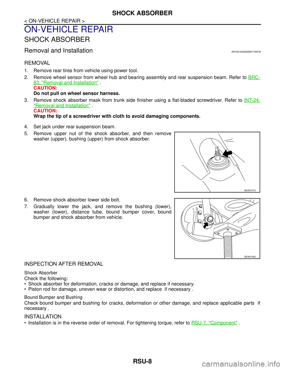
5. Remove upper nut of the shock absorber, and then remove
washer (upper), bushing (upper) from shock absorber.
6. Remove shock absorber lower side bolt.
7. Gradually lower the jack, and remove the bushing (lower),
washer (lower), distance tube, bound bumper cover, bound
bumper and shock absorber from vehicle.
INSPECTION AFTER REMOVAL
Shock Absorber
Check the following:
Shock absorber for deformation, cracks or damage, and replace if necessary.
Piston rod for damage, uneven wear or distortion, and replace if necessary .
Bound Bumper and Bushing
Check bound bumper and bushing for cracks, deformation or other damage, and replace applicable parts if
necessary .
INSTALLATION
Installation is in the reverse order of removal. For tightening torque, refer to RSU-7, "Component" .
SEIA0147J
SEIA0146J
Page 4582 of 5883
RSU-10
< ON-VEHICLE REPAIR >
COIL SPRING
COIL SPRING
Removal and InstallationINFOID:0000000001724579
REMOVAL
1. Remove rear tires from vehicle using power tool.
2. Remove wheel sensor from wheel hub and bearing assembly. Refer to BRC-83, "
Removal and Installa-
tion" .
CAUTION:
Do not pull on wheel sensor harness.
3. Separate brake tube from wheel cylinder. Refer to BR-15, "
Rear Brake Tube and Hose" .
4. Set jack under rear suspension beam.
5. Remove shock absorber lower side bolt. Refer to RSU-8,
"Removal and Installation" .
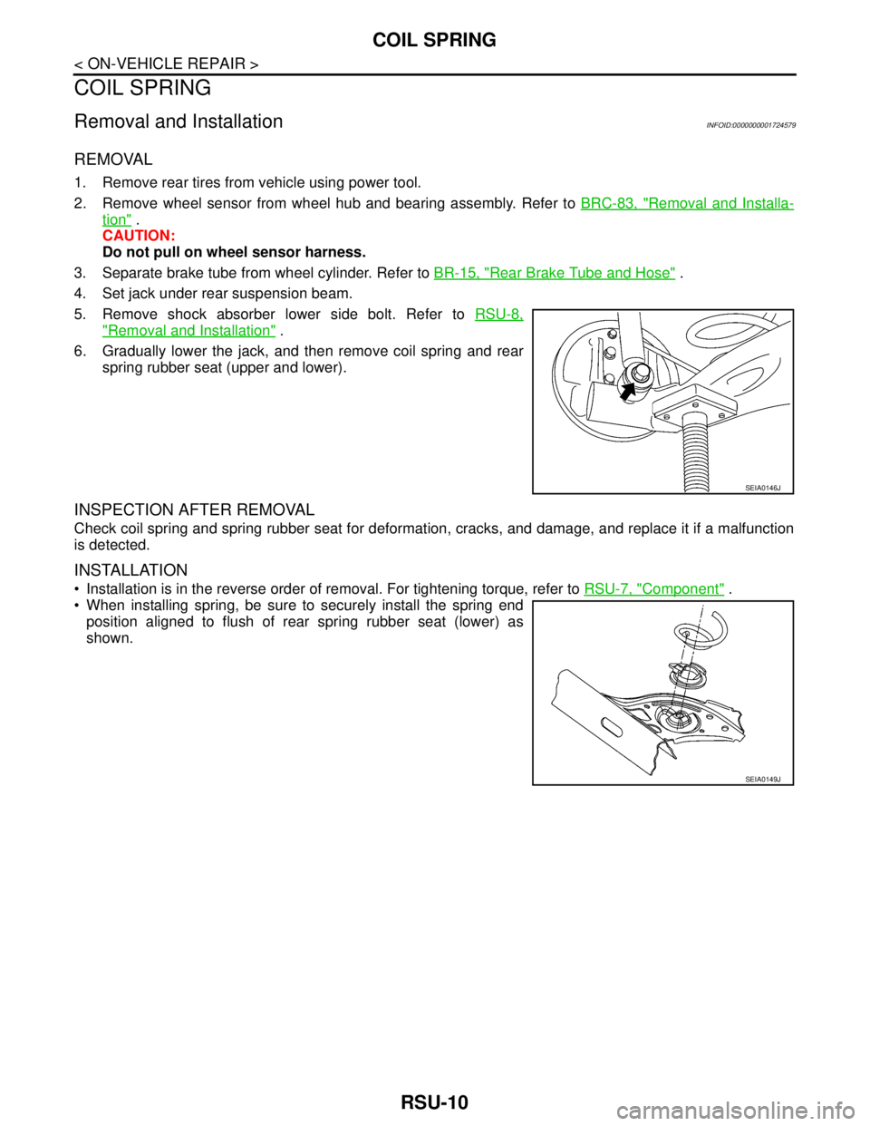
6. Gradually lower the jack, and then remove coil spring and rear
spring rubber seat (upper and lower).
INSPECTION AFTER REMOVAL
Check coil spring and spring rubber seat for deformation, cracks, and damage, and replace it if a malfunction
is detected.
INSTALLATION
Installation is in the reverse order of removal. For tightening torque, refer to RSU-7, "Component" .
When installing spring, be sure to securely install the spring end
position aligned to flush of rear spring rubber seat (lower) as
shown.
SEIA0146J
SEIA0149J
Page 4583 of 5883
REAR SUSPENSION BEAM
RSU-11
< ON-VEHICLE REPAIR >
C
D
F
G
H
I
J
K
L
MA
B
RSU
N
O
P
REAR SUSPENSION BEAM
Removal and InstallationINFOID:0000000001724580
REMOVAL
1. Remove rear tires from vehicle using power tool.
2. Separate parking brake rear cable from rear drum brake and rear suspension beam. Refer to PB-4, "
On-
Vehicle Service" .
3. Remove wheel sensor and wheel sensor harness from wheel hub and bearing assembly and rear suspen-
sion beam. Refer to BRC-83, "
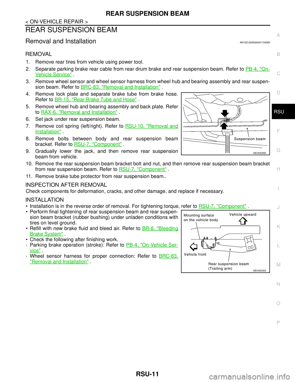
Removal and Installation" .
4. Remove lock plate and separate brake tube from brake hose.
Refer to BR-15, "
Rear Brake Tube and Hose" .
5. Remove wheel hub and bearing assembly and back plate. Refer
to RAX-6, "
Removal and Installation" .
6. Set jack under rear suspension beam.
7. Remove coil spring (left/right). Refer to RSU-10, "
Removal and
Installation" .
8. Remove bolts between body and rear suspension beam
bracket. Refer to RSU-7, "
Component" .
9. Gradually lower the jack, and then remove rear suspension
beam from vehicle.
10. Remove the rear suspension beam bracket bolt and nut, and then remove rear suspension beam bracket
from rear suspension beam. Refer to RSU-7, "
Component" .
11. Remove brake tube protector from rear suspension beam..
INSPECTION AFTER REMOVAL
Check components for deformation, cracks, and other damage, and replace if necessary.
INSTALLATION
Installation is in the reverse order of removal. For tightening torque, refer to RSU-7, "Component" .
Perform final tightening of rear suspension beam and rear suspen-
sion beam bracket (rubber bushing) under unladen conditions with
tires on level ground.
Refill with new brake fluid and bleed air. Refer to BR-8, "
Bleeding
Brake System" .
Check the following after finishing work.
- Parking brake operation (stroke): Refer to PB-4, "
On-Vehicle Ser-
vice" .
- Wheel sensor harness for proper connection: Refer to BRC-83,
"Removal and Installation" .
MEIA0029E
MEIA0030E
Page 4591 of 5883
FRONT SEAT BELT
SB-7
< ON-VEHICLE REPAIR >
C
D
E
F
G
I
J
K
L
MA
B
SB
N
O
P
2. Remove the adjuster cover and D-ring anchor bolt.
3. Remove both the center pillar upper and lower garnish. Refer to INT-20, "
Removal and Installation".
WARNING:
Do not reuse center pillar upper garnish if removed.
4. Pull the floor trim away from center pillar.
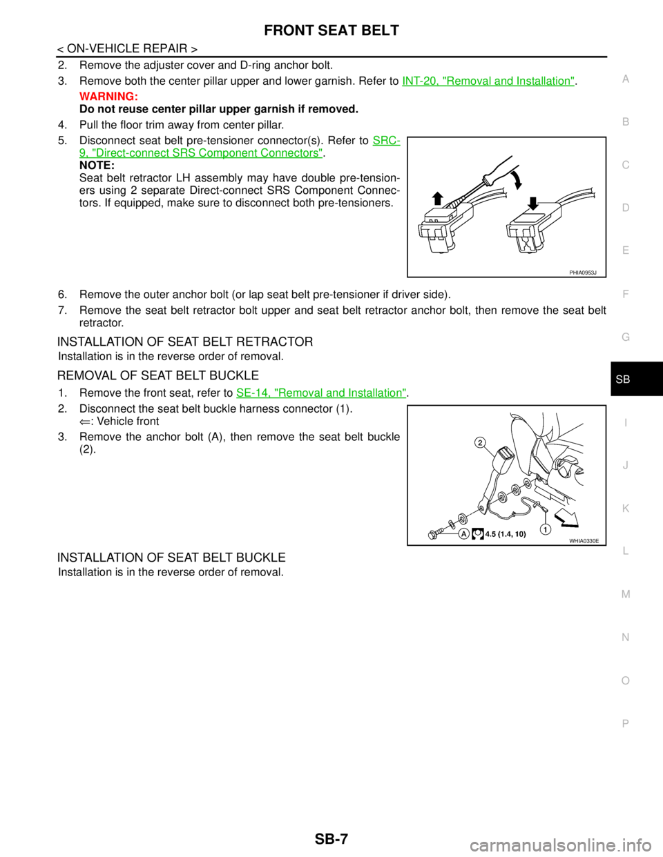
5. Disconnect seat belt pre-tensioner connector(s). Refer to SRC-
9, "Direct-connect SRS Component Connectors".
NOTE:
Seat belt retractor LH assembly may have double pre-tension-
ers using 2 separate Direct-connect SRS Component Connec-
tors. If equipped, make sure to disconnect both pre-tensioners.
6. Remove the outer anchor bolt (or lap seat belt pre-tensioner if driver side).
7. Remove the seat belt retractor bolt upper and seat belt retractor anchor bolt, then remove the seat belt
retractor.
INSTALLATION OF SEAT BELT RETRACTOR
Installation is in the reverse order of removal.
REMOVAL OF SEAT BELT BUCKLE
1. Remove the front seat, refer to SE-14, "Removal and Installation".
2. Disconnect the seat belt buckle harness connector (1).
⇐: Vehicle front
3. Remove the anchor bolt (A), then remove the seat belt buckle
(2).
INSTALLATION OF SEAT BELT BUCKLE
Installation is in the reverse order of removal.
PHIA0953J
WHIA0330E
Page 4594 of 5883
SB-10
< ON-VEHICLE REPAIR >
REAR SEAT BELT
5. Remove the outer retractor anchor bolt, then remove outer seat belt retractor.
INSTALLATION OF OUTER SEAT BELT RETRACTOR - HATCHBACK
Installation is in the reverse order of removal.
REMOVAL OF OUTER SEAT BELT RETRACTOR - SEDAN
1. Remove rear seat cushion, refer to SE-18, "Removal and Installation".
2. Remove outer seat belt anchor bolt.
3. Release the seat belt escutcheon, then remove from belt.
4. Remove rear parcel shelf finisher, refer to INT-26, "
Removal and Installation".
5. Remove outer seat belt retractor bolt, then remove outer seat belt retractor.
INSTALLATION OF OUTER SEAT BELT RETRACTOR - SEDAN
Installation is in the reverse order of removal.
REMOVAL OF CENTER SEAT BELT RETRACTOR - HATCHBACK
1. Remove and disassemble the rear seat cushion, refer to SE-18, "Removal and Installation".
2. Remove the center seat belt retractor.
INSTALLATION OF CENTER SEAT BELT RETRACTOR - HATCHBACK
Installation is in the reverse order of removal.
REMOVAL OF CENTER SEAT BELT RETRACTOR - SEDAN
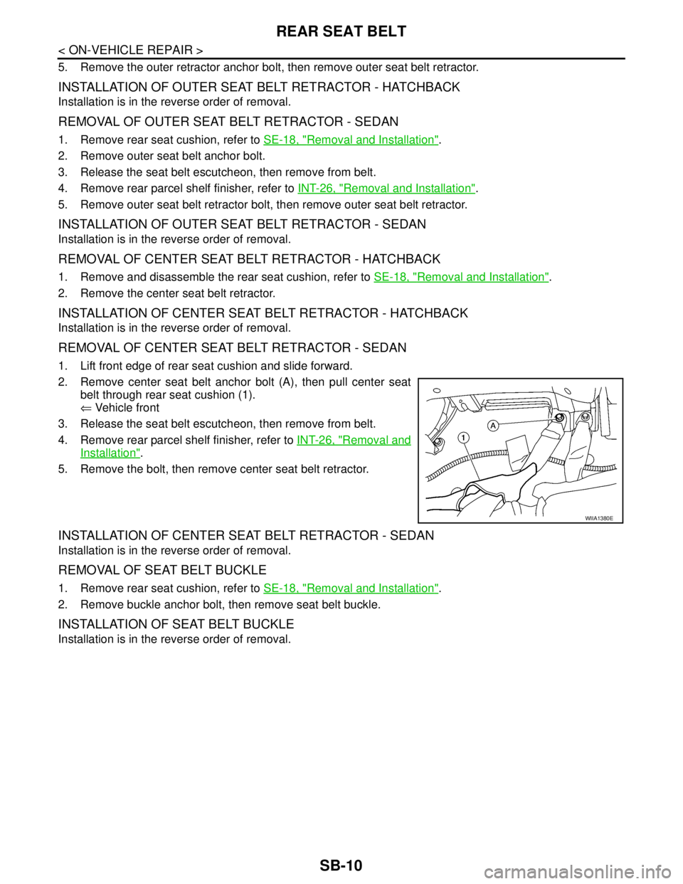
1. Lift front edge of rear seat cushion and slide forward.
2. Remove center seat belt anchor bolt (A), then pull center seat
belt through rear seat cushion (1).
⇐ Vehicle front
3. Release the seat belt escutcheon, then remove from belt.
4. Remove rear parcel shelf finisher, refer to INT-26, "
Removal and
Installation".
5. Remove the bolt, then remove center seat belt retractor.
INSTALLATION OF CENTER SEAT BELT RETRACTOR - SEDAN
Installation is in the reverse order of removal.
REMOVAL OF SEAT BELT BUCKLE
1. Remove rear seat cushion, refer to SE-18, "Removal and Installation".
2. Remove buckle anchor bolt, then remove seat belt buckle.
INSTALLATION OF SEAT BELT BUCKLE
Installation is in the reverse order of removal.
WIIA1380E