Page 4239 of 5883
LU-32
< ON-VEHICLE REPAIR >[K9K]
OIL PUMP
OIL PUMP
Exploded ViewINFOID:0000000001381546
Removal and InstallationINFOID:0000000001381547
REMOVAL
1. Remove the battery negative cable.
2. Remove the engine undercover.
3. Remove the RH front wheel and tire. Refer to WT-6, "
Rotation".
4. Remove RH fender protector. Refer to EXT-22, "
Removal and Installation".
5. Remove front driveshaft assembly RH. Refer to FA X - 11 , "
Removal and Installation (Right Side)".
6. Remove driveshaft center bearing bracket.
7. Remove lower torque rod. Refer to EM-302, "
Exploded View".
8. Remove oil pan. Refer to EM-284, "
Removal and Installation".
9. Remove oil pump drive chain.
10. Remove oil pump assembly.
INSTALLATION
Installation is in the reverse order of removal.
1. Oil pump drive chain 2. Crankshaft sprocket (oil pump drive
chain)3. Oil pump
E1BIA0028GB
Page 4266 of 5883
MA-26
< ON-VEHICLE MAINTENANCE >
ENGINE MAINTENANCE (HR16DE)
AIR CLEANER FILTER : Removal and Installation
INFOID:0000000001730850
REMOVAL
1. Push the tabs (A) of both ends of the air cleaner cover (1) into
the inside (B).
2. Pull up the air cleaner cover (1) and remove it (C).
3. Remove air cleaner filter (1) and holder (2) assembly from the
air cleaner case.
4. Remove the air cleaner filter (1) from the holder (2).
INSPECTION AFTER REMOVAL
It is necessary to clean air cleaner filter or replace it at the recommended intervals, more often under dusty
conditions. Refer to MA-7, "
Periodic Maintenance".
Blow air into the back side of air cleaner filter until no objects spray
out.
INSTALLATION
Installation is in the reverse order of removal.
Install the air cleaner cover (1) in the direction shown.
ENGINE OIL
PBIC3557J
PBIC3558J
SMA384C
2 : Air cleaner filter
3 : Holder
PBIC3559J
Page 4269 of 5883

ENGINE MAINTENANCE (HR16DE)
MA-29
< ON-VEHICLE MAINTENANCE >
C
D
E
F
G
H
I
J
K
L
MB
MAN
OA
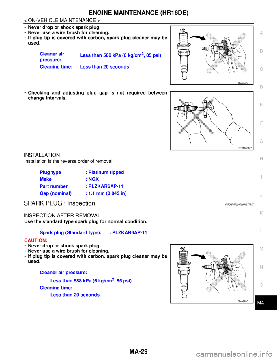
Never drop or shock spark plug.
Never use a wire brush for cleaning.
If plug tip is covered with carbon, spark plug cleaner may be
used.
Checking and adjusting plug gap is not required between
change intervals.
INSTALLATION
Installation is the reverse order of removal.
SPARK PLUG : InspectionINFOID:0000000001277617
INSPECTION AFTER REMOVAL
Use the standard type spark plug for normal condition.
CAUTION:
Never drop or shock spark plug.
Never use a wire brush for cleaning.
If plug tip is covered with carbon, spark plug cleaner may be
used.Cleaner air
pressure:Less than 588 kPa (6 kg/cm
2, 85 psi)
Cleaning time: Less than 20 seconds
SMA773C
JPBIA0031ZZ
Plug type : Platinum tipped
Make : NGK
Part number : PLZKAR6AP-11
Gap (nominal) : 1.1 mm (0.043 in)
Spark plug (Standard type): : PLZKAR6AP-11
Cleaner air pressure:
Less than 588 kPa (6 kg/cm
2, 85 psi)
Cleaning time:
Less than 20 seconds
SMA773C
Page 4275 of 5883

ENGINE MAINTENANCE (MR18DE)
MA-35
< ON-VEHICLE MAINTENANCE >
C
D
E
F
G
H
I
J
K
L
MB
MAN
OA
FUEL LINES : InspectionINFOID:0000000001277628
Inspect fuel lines, filler cap and tank for improper attachment, leaks,
cracks, damage, loose connections, chafing or deterioration.
If necessary, repair or replace damaged parts.
AIR CLEANER FILTER
AIR CLEANER FILTER : Removal and InstallationINFOID:0000000001730862
REMOVAL
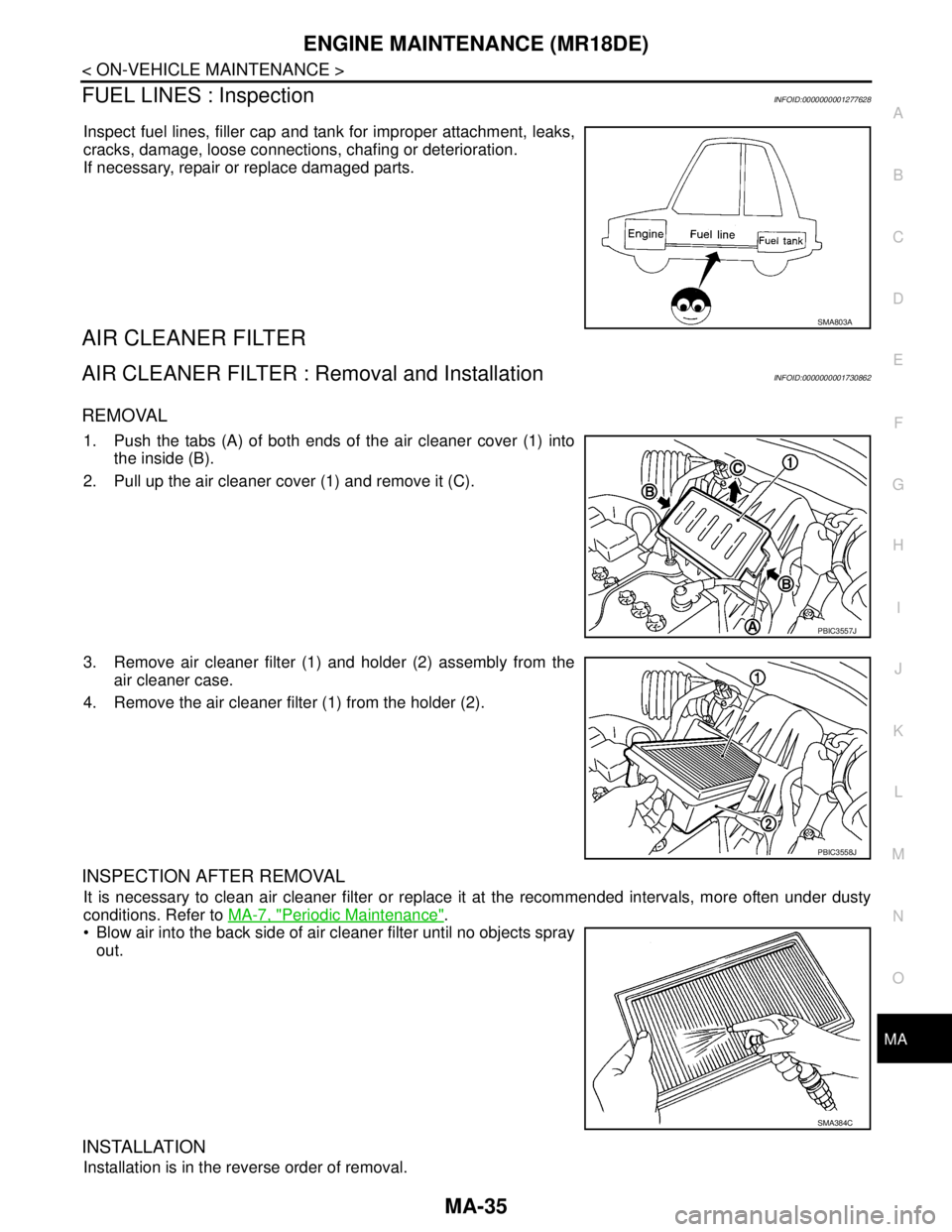
1. Push the tabs (A) of both ends of the air cleaner cover (1) into
the inside (B).
2. Pull up the air cleaner cover (1) and remove it (C).
3. Remove air cleaner filter (1) and holder (2) assembly from the
air cleaner case.
4. Remove the air cleaner filter (1) from the holder (2).
INSPECTION AFTER REMOVAL
It is necessary to clean air cleaner filter or replace it at the recommended intervals, more often under dusty
conditions. Refer to MA-7, "
Periodic Maintenance".
Blow air into the back side of air cleaner filter until no objects spray
out.
INSTALLATION
Installation is in the reverse order of removal.
SMA803A
PBIC3557J
PBIC3558J
SMA384C
Page 4286 of 5883
MA-46
< ON-VEHICLE MAINTENANCE >
ENGINE MAINTENANCE (K9K)
AIR CLEANER FILTER
AIR CLEANER FILTER : Removal and InstallationINFOID:0000000001730875
REMOVAL
1. Push the tabs (A) of both ends of the air cleaner cover (1) into
the inside (B).
2. Pull up the air cleaner cover (1) and remove it (C).
3. Remove air cleaner filter (1) and holder (2) assembly from the
air cleaner case.
4. Remove the air cleaner filter (1) from the holder (2).
INSPECTION AFTER REMOVAL
It is necessary to clean air cleaner filter or replace it at the recommended intervals, more often under dusty
conditions. Refer to MA-7, "
Periodic Maintenance".
Blow air into the back side of air cleaner filter until no objects spray
out.
INSTALLATION
Installation is in the reverse order of removal.
Install the air cleaner cover (1) in the direction shown.
ENGINE OIL
PBIC3557J
PBIC3558J
SMA384C
2 : Air cleaner filter
3 : Holder
PBIC3559J
Page 4305 of 5883
DOOR MIRROR
MIR-7
< REMOVAL AND INSTALLATION >
C
D
E
F
G
H
I
J
K
MA
B
MIR
N
O
P
REMOVAL AND INSTALLATION
DOOR MIRROR
Removal and InstallationINFOID:0000000001716808
CAUTION:
Be careful not to damage the mirror body.
REMOVAL
1. Remove the front door finisher. Refer to INT-13, "Removal and Installation".
2. Disconnect the harness connector of door mirror.
3. Using a suitable tool remove door mirror base cover.
CAUTION:
Do not reuse the disassembled door mirror base cover.
Be careful not to damage the door panel with a tool.
4. Remove the door mirror bolts, and remove the door mirror
assembly.
CAUTION:
Do not use force to remove the door mirror assembly by
force because it is attached by clip.
INSTALLATION
Installation is in the reverse order of removal.
PIIB2638J
1. Door mirror base cover 2. Door mirror
PIIB2679E
PIIB6288E
Page 4307 of 5883
INSIDE MIRROR
MIR-9
< REMOVAL AND INSTALLATION >
C
D
E
F
G
H
I
J
K
MA
B
MIR
N
O
P
INSIDE MIRROR
Removal and InstallationINFOID:0000000001716810
REMOVAL
Slide the inside mirror upward, and then remove inside mirror (1)
from the mirror base (2).
CAUTION:
Do not use excessive force to remove the inside mirror
because it is inserted tightly into the mirror base.
Do not reuse the inside mirror disassembled from mirror
base.
INSTALLATION
Installation is in the reverse order of removal.
CAUTION:
Be sure to insert the inside mirror to the mirror base until the pawl is engaged to the mirror base.
PIIB6289E
Page 4370 of 5883

MWI
BCM (BODY CONTROL MODULE)
MWI-63
< ECU DIAGNOSIS >
C
D
E
F
G
H
I
J
K
L
MB A
O
P
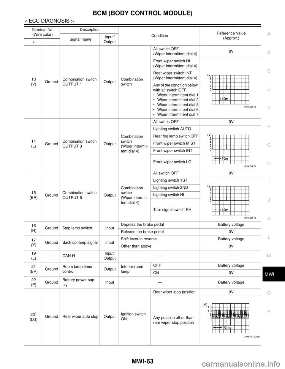
13
(V)GroundCombination switch
OUTPUT 1OutputCombination
switchAll switch OFF
(Wiper intermittent dial 4)0V
Front wiper switch HI
(Wiper intermittent dial 4)
Rear wiper switch INT
(Wiper intermittent dial 4)
Any of the condition below
with all switch OFF
Wiper intermittent dial 1
Wiper intermittent dial 2
Wiper intermittent dial 3
Wiper intermittent dial 6
Wiper intermittent dial 7
14
(L)GroundCombination switch
OUTPUT 3OutputCombination
switch
(Wiper intermit-
tent dial 4)All switch OFF 0V
Lighting switch AUTO
Rear fog lamp switch OFF
Front wiper switch MIST
Front wiper switch INT
Front wiper switch LO
15
(BR)GroundCombination switch
OUTPUT 5OutputCombination
switch
(Wiper intermit-
tent dial 4)All switch OFF 0V
Lighting switch 1ST
Lighting switch 2ND
Lighting switch HI
Turn signal switch RH
16
(R)Ground Stop lamp switch InputDepress the brake pedal Battery voltage
Release the brake pedal 0V
17
(Y)Ground Back up lamp signal InputShift lever in reverse Battery voltage
Other than above 0V
19
(L)—CAN-HInput/
Output——
21
(BR)GroundRoom lamp timer
controlOutputInterior room
lampOFF Battery voltage
ON 0V
22
(P)GroundBattery power sup-
plyInput — Battery voltage
23
1
(LG)Ground Rear wiper auto stop OutputIgnition switch
ONRear wiper stop position 0V
Any position other than
rear wiper stop position Terminal No.
(Wire color)Description
ConditionReference Value
(Approx.)
Signal nameInput/
Output +−
SKIA2167J
SKIA2167J
SKIA2167J
JPMIA0197GB