Page 1430 of 1449

HEATER, AIR CONDITIONER AND VENTILATION-Heater Unit and Blower Assembly55-28
HEATER UNIT AND BLOWER ASSEMBLY
REMOVAL AND INSTALLATION
Pre-removal and Post-installation Operations
DRefrigerant Draining and Refilling (Refer to P.55-16, 19.)
DCoolant Draining and Refilling (Refer to GROUP 14 – On - vehicle Service.)
DInstrument Panel Removal and Installation (Refer to GROUP 52A – Instrument Panel.)
DFront Seat Removal and Installation (Refer to GROUP 52A – Front Seat.)
DFloor Console Removal and Installation (Refer to GROUP 52A – Floor Console.)
DFloor Carpet Removal and Installation
13
5 6
2
12±2 N·m
- Pipe coupling
O-ring
A/C compressor oil:
SUN PAG 56
4, 5
9
7
4
8
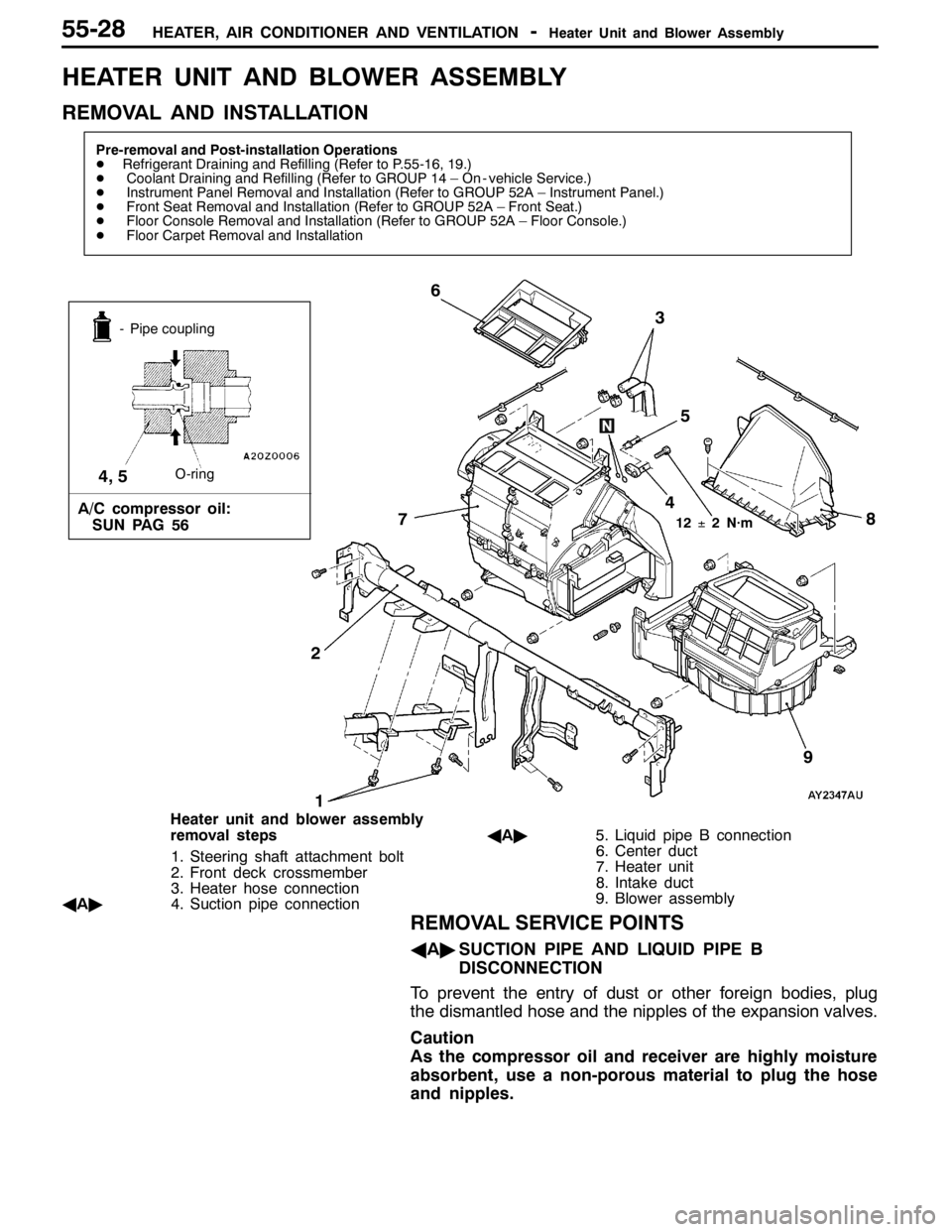
Heater unit and blower assembly
removal steps
1. Steering shaft attachment bolt
2. Front deck crossmember
3. Heater hose connection
AA"4. Suction pipe connectionAA"5. Liquid pipe B connection
6. Center duct
7. Heater unit
8. Intake duct
9. Blower assembly
REMOVAL SERVICE POINTS
AA"SUCTION PIPE AND LIQUID PIPE B
DISCONNECTION
To prevent the entry of dust or other foreign bodies, plug
the dismantled hose and the nipples of the expansion valves.
Caution
As the compressor oil and receiver are highly moisture
absorbent, use a non-porous material to plug the hose
and nipples.
Page 1434 of 1449
Resister, Blower Motor, Inside/outside
Air Changeover Damper MotorHEATER, AIR CONDITIONER AND VENTILATION-55-32
RESISTER, BLOWER MOTOR AND INSIDE/OUTSIDE AIR CHANGE
OVER DAMPER MOTOR
REMOVAL AND INSTALLATION
12
3
Resister removal steps
DGlove box (Refer to GROUP 52A –
Instrument Panel.)
DEngine-ECU (Refer to GROUP 14.)
1. Resister
Blower motor removal steps
AA"2. Blower motorInside/outside air changeover
damper motor removal steps
DGlove box (Refer to GROUP 52A –
Instrument Panel.)
DEngine-ECU (Refer to GROUP 14.)
3. Inside/outside air changeover damper
motor
REMOVAL SERVICE POINTS
AA"BLOWER MOTOR REMOVAL
NOTE
Use of commercially available offset screw driver is
recommended.
Page 1436 of 1449

HEATER, AIR CONDITIONER AND VENTILATION-Evaporator and Air Thermo Sensor55-34
EVAPORATOR AND AIR THERMO SENSOR
REMOVAL AND INSTALLATION
Pre-removal and Post-installation Operations
DRefrigerant Draining and Refilling (Refer to P.55-16, 19.)
1 2
3
4
56
7 8
12±2 N·m
- Pipe coupling
O-ring
A/C compressor oil:
SUN PAG 56
1, 2
9
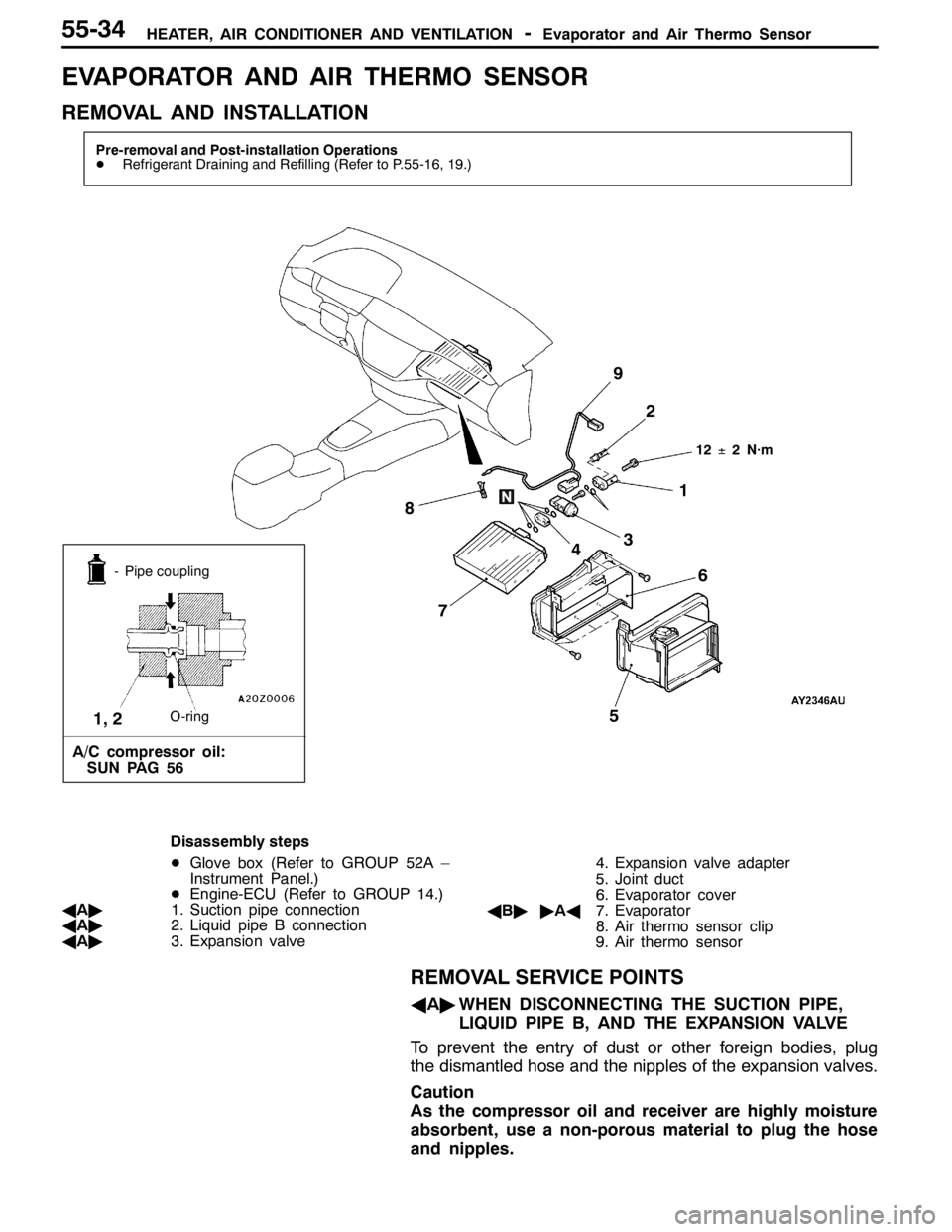
Disassembly steps
DGlove box (Refer to GROUP 52A –
Instrument Panel.)
DEngine-ECU (Refer to GROUP 14.)
AA"1. Suction pipe connection
AA"2. Liquid pipe B connection
AA"3. Expansion valve4. Expansion valve adapter
5. Joint duct
6. Evaporator cover
AB""AA7. Evaporator
8. Air thermo sensor clip
9. Air thermo sensor
REMOVAL SERVICE POINTS
AA"WHEN DISCONNECTING THE SUCTION PIPE,
LIQUID PIPE B, AND THE EXPANSION VALVE
To prevent the entry of dust or other foreign bodies, plug
the dismantled hose and the nipples of the expansion valves.
Caution
As the compressor oil and receiver are highly moisture
absorbent, use a non-porous material to plug the hose
and nipples.
Page 1446 of 1449
HEATER, AIR CONDITIONER AND VENTILATION-Ducts55-44
DUCTS
REMOVAL AND INSTALLATION
4
3 5 4
8
76
1 2 3
A
A
Cross-section A - A
Clip
Instrument panel
1
Air outlet removal steps
1. Center air outlet panel
2. Center air outlet
3. Side air outlet
Defroster nozzle and distribution
duct removal steps
DInstrument panel (Refer to GROUP
52A.)
4. Side defroster duct5. Defroster nozzle
6. Distribution duct
Foot duct removal step
DConsole cover and glove box (Refer
to GROUP 52A – Instrument Panel.)
7. Right-hand foot duct
DUnder cover (Refer to GROUP 52A
– Instrument Panel.)
8. Left-hand foot duct