Page 43 of 1449

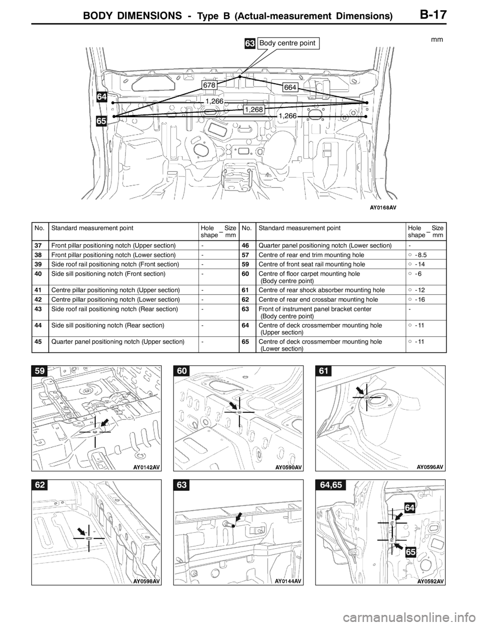
BODY DIMENSIONS -Type B (Actual-measurement Dimensions)
596061
6263
65
64,65
64
B-17
1,266
1,266
Body centre point
664678
1,268
64
65
63mm
No.Standard measurement pointHoleSize
shape mmNo.Standard measurement pointHoleSize
shape mm
37Front pillar positioning notch (Upper section)-46Quarter panel positioning notch (Lower section)-
38Front pillar positioning notch (Lower section)-57Centre of rear end trim mounting hole�Ó- 8.5
39Side roof rail positioning notch (Front section)-59Centre of front seat rail mounting hole�Ó-14
40Side sill positioning notch (Front section)-60Centre of floor carpet mounting hole
(Body centre point)�Ó-6
41Centre pillar positioning notch (Upper section)-61Centre of rear shock absorber mounting hole�Ó-12
42Centre pillar positioning notch (Lower section)-62Centre of rear end crossbar mounting hole�Ó-16
43Side roof rail positioning notch (Rear section)-63Front of instrument panel bracket center
(Body centre point)-
44Side sill positioning notch (Rear section)-64Centre of deck crossmember mounting hole
(Upper section)�Ó-11
45Quarter panel positioning notch (Upper section)-65Centre of deck crossmember mounting hole
(Lower section)�Ó-11
Page 79 of 1449

SYNTHETIC-RESIN PARTS -Location of Synthetic-resin PartsE-3
No.Part numberMaterialAbbreviation of
materialHeat-resistant
temperature (_C)
1
2Outside mirror
Rear spoilerAcrylonitrile
Butadiene styreneABS80
3Roof antennaAcrylonitrile
Ethylene butadieneAES90
4HeadlampPolycarbonatePC120
5
6
7Front bumper bezel
Rear door outside handle
Front door outside handlePolycarbonate +
Acrylonitrile butadiene styrenePC + ABS125 - 135
8Splash shieldPolyethylenePE100
9
10
11
12
13
14
15
16
17
18
19
20Oil cooler duct
Instrument panel
Front pillar trim
Inside rear view mirror
Centre pillar trim
Rear pillar trim
Rear door trim
Rear end trim
Rear scuff plate
Rear console box
Front scuff plate
Cowl side trimPolypropylenePP80
21
22
23
24Front bumper extension
Front bumper face
License plate garnish
Front door trimRubber denatured polypropylenePP + E/P80
25Rear bumper faceWith talc added rubber denatured
polypropylenePP + E/P - TD
(HMPP)80 - 100
26Side sill extensionWith 20% talc added rubber dena-
tured polypropylenePP + E/P - TD20
(HMPP)11 0
27Center pillar trim lowerWith 10 % talc added polypropylenePP - TD10
(PPF)110 - 120
28
29Front deck garnish
Floor consoleWith 20 % talc added polypropylenePP - TD20
(PPF)120 - 130
30Hood inlet upper garnishPolyphenylene ether + PolyamidePPE+PA
(PA/PPO)185
31Roof drip moldingPolyvinyl chloridePVC80
NOTE
1. If the new material symbols designated by the ISO differ from the old symbols, both are given, with
the old symbols enclosed in brackets.
ISO: (International Standardization Organization)
2. A slash (/) in the material symbol indicates that two different materials compose a 2-layer construction.
A plus sign (+) indicates that the two different materials are mixed.
3. The material symbols for synthetic-resin parts are embossed on parts in hidden places.
Page 102 of 1449
WIRING HARNESS CONFIGURATION DIAGRAMSB-4
WIRING HARNESS CONFIGURATION DIAGRAMS
OVERALL WIRING DIAGRAM
L.H. drive vehicles
Front wiring
harness (RH)
Control wiring
harnessInstrument panel
wiring harnessRoof wiring
harnessFloor wiring
harness (RH)
Battery wiring
harnessFront wiring
harness (LH)Front door
wiring harness*Floor wiring
harness (LH)Fuel wiring
harness
Rear door
wiring harness*
NOTE
(1) This illustration shows only major wiring harness.
(2) *: also equipped at the right side.
Page 103 of 1449
WIRING HARNESS CONFIGURATION DIAGRAMSB-5
R.H. drive vehicles
Front wiring
harness (RH)
Control wiring
harnessInstrument panel
wiring harnessRoof wiring
harnessFloor wiring
harness (RH)
Battery wiring
harnessFront wiring
harness (LH)Front door
wiring harness*Floor wiring
harness (LH)Fuel wiring
harness
Rear door
wiring harness*
Page 116 of 1449
WIRING HARNESS CONFIGURATION DIAGRAMS
Connector
symbol
-01
thru
-45
C
C-29
C-05C-04C-03C-32C-02C-01
C-36
C-26
C-24
C-45
C-23C-22C-42C-41C-21
67
5
16
17
15
J/B
Y
B-18
DASH PANEL
L.H. drive vehicles
C-01 (21) Combination meter
C-02 (21-L) Combination meter
C-03 (4) Hazard warning switch
C-04 (4) Clock
C-05 (22-GR) J/C (1)
C-08 (22-GR) J/C (3)
C-10 (7) Outside/Inside air selection damper
control motor and potentiometerC-14 (2) Blower motor
C-16 (4) Resistor
C-21 (20-Y) SRS-ECU
C-22 (16-B) Diagnosis connector
C-23 (12) Diagnosis connector
C-24 (20) Instrument panel wiring harness and front
door wiring harness (LH) combination
Page 117 of 1449
WIRING HARNESS CONFIGURATION DIAGRAMS
C-08
C-16
C-10
C-14
2
3
Y
Connector colour code
B:Black
Y:Yellow
L:Blue
G:Green
R:Red
BR:Brown
V:Violet
O:Orange
GR:Gray
None: Milk white
C-44C-43
B-19
C-26 (22-B) J/C (4)
C-29 (22-B) J/C (5)
C-32 (16-B) A/C-ECU or heater control unit
C-36 (6-GR) Headlamp leveling switch
C-41 (22-Y) SRS-ECU
C-42 (1) Instrument panel wiring harness and
control wiring harness combination
C-43 (22-Y) 4WD-ECU
C-44 (26-Y) 4WD-ECU
C-45 (1) Instrument panel wiring harness and floor
wiring harness (LH) combination
Page 118 of 1449
WIRING HARNESS CONFIGURATION DIAGRAMS
Connector
symbol
-101
thru
-146
C
C-137
C-135
C-134
C-133
C-132
C-131C-130C-129C-128
C-141C-104C-103C-102C-142C-138C-101C-108
5
6
7
15
16
17
J/B
Y
B-20
L.H. drive vehicles
C-101 (1) Spare connector (for front fog lamp
switch)
C-102 (22-L) J/C (2)
C-103 (4) Stop lamp switch
C-104 (14) Spare connector (for radio)
C-107 (7) Instrument panel wiring harness and A/C
wiring harness combination
C-108 (33) J/C (6)
C-109 (2-R) Air bag module (squib)
side>C-110 (16) Instrument panel wiring harness and front
door wiring harness (RH) combination
C-111 (25) Front wiring harness (RH) and instrument
panel wiring harness combination
C-112 (13) Instrument panel wiring harness and floor
wiring harness (RH) combination
C-115 (22-Y) Engine-ECU
C-118 (12-Y) Engine-ECU
C-122 (16-Y) Engine-ECU
C-126 (26-Y) Engine-ECU
Page 119 of 1449

WIRING HARNESS CONFIGURATION DIAGRAMS
C-115
C-107C-109
C-110
C-111
C-118C-122C-126C-112C-146
2
3
Y
Connector colour code
B:Black
Y:Yellow
L:Blue
G:Green
R:Red
BR:Brown
V:Violet
O:Orange
GR:Gray
None: Milk white
B-21
C-128 (22-L) Instrument panel wiring harness and
control wiring harness combination
C-129 (10-GR) Instrument panel wiring harness and
control wiring harness combination
C-130 (25) Instrument panel wiring harness and
control wiring harness combination
C-131 (6) Blower switch
C-132 (3) Front wiring harness (LH) and instrument
panel wiring harness combination
C-133 (13) Instrument panel wiring harness and floor
wiring harness (LH) combinationC-134 (11-GR) Instrument panel wiring harness and floor
wiring harness (LH) combination
C-135 (25) Front wiring harness (LH) and instrument
panel wiring harness combination
C-137 (6) Fog lamp switch
C-138 (11-GR) Remote controlled mirror switch
C-141 (1) Roof antenna
C-142 (6) ACD mode changeover switch
C-146 (9-GR) Instrument panel wiring harness and floor
wiring harness (RH) combination