2007 MITSUBISHI LANCER EVOLUTION rear
[x] Cancel search: rearPage 537 of 1449

MPI -General Information13A-5
MULTI-POINT FUEL INJECTION SYSTEM DIAGRAM
L1 Oxygen sensor (front)
L2 Oxygen sensor (rear)
L3 Air flow sensor
L4 Intake air temperature sensor
L5 Throttle position sensor
L6 Camshaft position sensor
L7 Crank angle sensor
L8 Barometric pressure sensor
L9 Engine coolant temperature sensor
L10 Detonation sensor
Engine-ECU
l1 Injector
l2 Idle speed control servo
l3 Fuel pressure control solenoid valve
l4 Waste gate solenoid valve
l5 EGR control solenoid valve
l6 Purge control solenoid valve
l7 Secondary air control solenoid valve
DPower supply
DIgnition switch IG
DIgnition switch ST
DVehicle speed sensor
DA/C switch
DA/C load signal
DTachometer
DPower steering fluid pressure switch
DAlternator FR terminal
DDiagnosis control terminal
DIntercooler water spray switch (automatic)
DIntercooler water spray switch (manual)DEngine control relay
DFuel pump relay 2, 3
DA/C relay
DIgnition coil
DFan controller
DCondenser fan relay (HI)
DCondenser fan relay (LOW)
DEngine warning lamp
DDiagnosis output
DAlternator G terminal
DIntercooler water spray relay
DIntercooler water spray lamp
L1 Oxygen
sensor
(front)
L4 Intake air
temperature
sensorL5 Throttle
position
sensor
L6 Camshaft
position sensorl1 Injector l2 Idle
speed
control
servo
l6 Purge
control
solenoid
valve
Three-way
catalytic converter Canister
Air
inletVacuum
tank
Fuel
pressure
reguratorFrom
fuel tank
To fuel tank
PCV valveFrom
fuel pump
Waste gate
actuatorL2 Oxygen sensor (rear) Check
valveBy-pass
valve
l5 EGR control
solenoid valve
l4 Waste gate
solenoid valve L8 Barometric
pressure
sensor
L3 Air flow
sensorl7 Secondary
air control
solenoid
valve
Secondary
air valvel3 Fuel pressure
control
solenoid valve
EGR
valve
L9 Engine coolant
temperature sensor
L7 Crank angle sensor
L10 Detonation sensor
Page 538 of 1449

MPI -Service Specifications/Sealant13A-6
SERVICE SPECIFICATIONS
ItemsSpecifications
Basic idle speed r/min850±100
Throttle position sensor adjusting voltage mV535 - 735
Throttle position sensor resistance kΩ3.5 - 6.5
Idle speed control servo coil resistance (at 20_C)Ω28 - 33
Intake air temperature sensor
resistancekΩ
-20_C13 - 17
resistance kΩ0_C5.7 - 6.7
20_C2.3 - 3.0
40_C1.0 - 1.5
60_C0.56 - 0.76
80_C0.30 - 0.42
Engine coolant temperature
sensorresistancekΩ
-20_C14 - 17
sensor resistance kΩ0_C5.1 - 6.5
20_C2.1 - 2.7
40_C0.9 - 1.3
60_C0.48 - 0.68
80_C0.26 - 0.36
Oxygen sensor heater
resistance(at20_C)Ω
Front4.5 - 8.0
resistance (at 20_C)ΩRear11 - 1 8
Oxygen sensor output voltage (at racing) V0.6 - 1.0
Fuel pressure kPaVacuum hose disconnection289 - 309 at curb idle
Vacuum hose connectionApproximately 230 at curb idle
Fuel pressure control solenoid valve resistance (at 20_C)Ω28 - 36
Fuel pump resistor resistanceΩ0.45 - 0.65
Injector coil resistance (at 20_C)Ω2-3
Injector fuel leakage rate Drop/minute1 or less
Resistor (for injector) resistance (at 20_C)Ω5.8 - 6.2
SEALANT
ItemSpecified sealantRemark
Engine coolant temperature sensor
threaded portion3M Nut Locking Part No. 4171 or equivalentDrying sealant
Page 541 of 1449

MPI -Troubleshooting13A-9
TROUBLESHOOTING
DIAGNOSIS TROUBLESHOOTING FLOW
Refer to GROUP 00 - How to Use Troubleshooting/Inspection
Service Point.
NOTE
If the engine-ECU is replaced, the immobilizer-ECU and
ignition key should be replaced together with it.
DIAGNOSIS FUNCTION
ENGINE WARNING LAMP (CHECK ENGINE LAMP)
If an abnormality occurs in any of the following items related
to the MPI system, the engine warning lamp will illuminate
or flash. If the lamp remains illuminated or if the lamp
illuminates while the engine is running, check the diagnosis
code output.
However, the warning lamp will illuminate as bulb check for
5 seconds whenever the ignition switch is turned to the ON
position.
Engine warning lamp inspection items
Code No.Diagnosis item
-Engine-ECU
P0100Air flow sensor system
P0105Barometric pressure sensor system
P0110Intake air temprature sensor system
P0115Engine coolant temperature sensor system
P0120Throttle position sensor system
P0130Oxygen sensor (front) system
P0135Oxygen sensor heater (front) system
P0136Oxygen sensor (rear) system
P0141Oxygen sensor heater (rear) system
P0201No.1 injector system
P0202No.2 injector system
P0203No.3 injector system
P0204No.4 injector system
P0325Detonation sensor system
P0335Crank angle sensor system
P0340Camshaft position sensor system
P0403EGR control solenoid valve system
Engine warning lamp
(check engine lamp)
Page 544 of 1449

MPI -Troubleshooting13A-12
INSPECTION CHART FOR DIAGNOSIS CODES
Code No.Diagnosis itemReference page
P0100Air flow sensor system13A-13
P0105Barometric pressure sensor system13A-15
P0110Intake air temprature sensor system13A-16
P0115Engine coolant temperature sensor system13A-19
P0120Throttle position sensor system13A-21
P0130Oxygen sensor (front) system13A-24
P0135Oxygen sensor heater (front) system13A-26
P0136Oxygen sensor (rear) system13A-27
P0141Oxygen sensor heater (rear) system13A-29
P0201No.1 injector system13A-30
P0202No.2 injector system13A-31
P0203No.3 injector system13A-32
P0204No.4 injector system13A-33
P0325Detonation sensor system13A-34
P0335Crank angle sensor system13A-35
P0340Camshaft position sensor system13A-37
P0403EGR control solenoid valve system13A-39
P0443Purge control solenoid valve system13A-41
P0500Vehicle speed sensor system13A-43
P0505Idle speed control system13A-44
P0551Power steering fluid pressure switch system13A-46
P1104Waste gate solenoid valve system13A-47
P1105Fuel pressure control valve system13A-48
P1500Alternator FR terminal system13A-49
P1603Battery backup line malfunction13A-50
P1610Immobilizer system13A-51
Page 559 of 1449

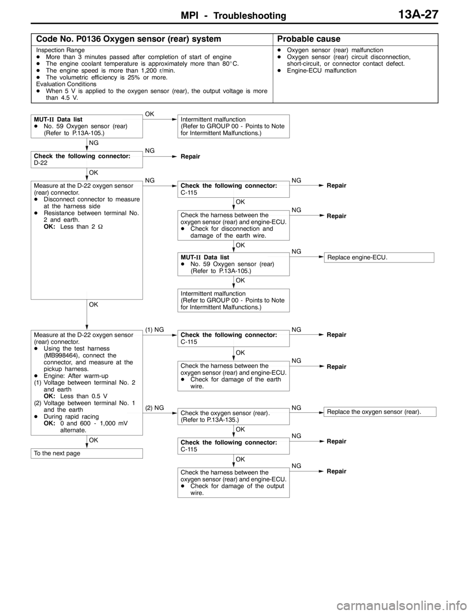
MPI -Troubleshooting13A-27
Code No. P0136 Oxygen sensor (rear) systemProbable cause
Inspection Range
DMore than 3 minutes passed after completion of start of engine
DThe engine coolant temperature is approximately more than 80_C.
DThe engine speed is more than 1,200 r/min.
DThe volumetric efficiency is 25% or more.
Evaluation Conditions
DWhen 5 V is applied to the oxygen sensor (rear), the output voltage is more
than 4.5 V.DOxygen sensor (rear) malfunction
DOxygen sensor (rear) circuit disconnection,
short-circuit, or connector contact defect.
DEngine-ECU malfunction
OK
To the next pageOK
Check the harness between the
oxygen sensor (rear) and engine-ECU.
DCheck for damage of the output
wire.NG
Repair NG
OK
Check the following connector:
C-115Repair
(2) NGCheck the oxygen sensor (rear).
(Refer to P.13A-135.)NGReplace the oxygen sensor (rear).
OK
Check the harness between the
oxygen sensor (rear) and engine-ECU.
DCheck for damage of the earth
wire.NG
Repair
OK
Measure at the D-22 oxygen sensor
(rear) connector.
DUsing the test harness
(MB998464), connect the
connector, and measure at the
pickup harness.
DEngine: After warm-up
(1) Voltage between terminal No. 2
and earth
OK:Less than 0.5 V
(2) Voltage between terminal No. 1
and the earth
DDuring rapid racing
OK:0 and 600 - 1,000 mV
alternate.(1) NGCheck the following connector:
C-115NG
Repair
OK
Intermittent malfunction
(Refer to GROUP 00 - Points to Note
for Intermittent Malfunctions.)
OK
MUT-IIData list
DNo. 59 Oxygen sensor (rear)
(Refer to P.13A-105.)NGReplace engine-ECU.
OK
Check the harness between the
oxygen sensor (rear) and engine-ECU.
DCheck for disconnection and
damage of the earth wire.NG
Repair
OK
Measure at the D-22 oxygen sensor
(rear) connector.
DDisconnect connector to measure
at the harness side
DResistance between terminal No.
2 and earth.
OK:Less than 2ΩNGCheck the following connector:
C-115NG
Repair
NG
Check the following connector:
D-22NG
Repair
MUT-IIData list
DNo. 59 Oxygen sensor (rear)
(Refer to P.13A-105.)OKIntermittent malfunction
(Refer to GROUP 00 - Points to Note
for Intermittent Malfunctions.)
Page 560 of 1449

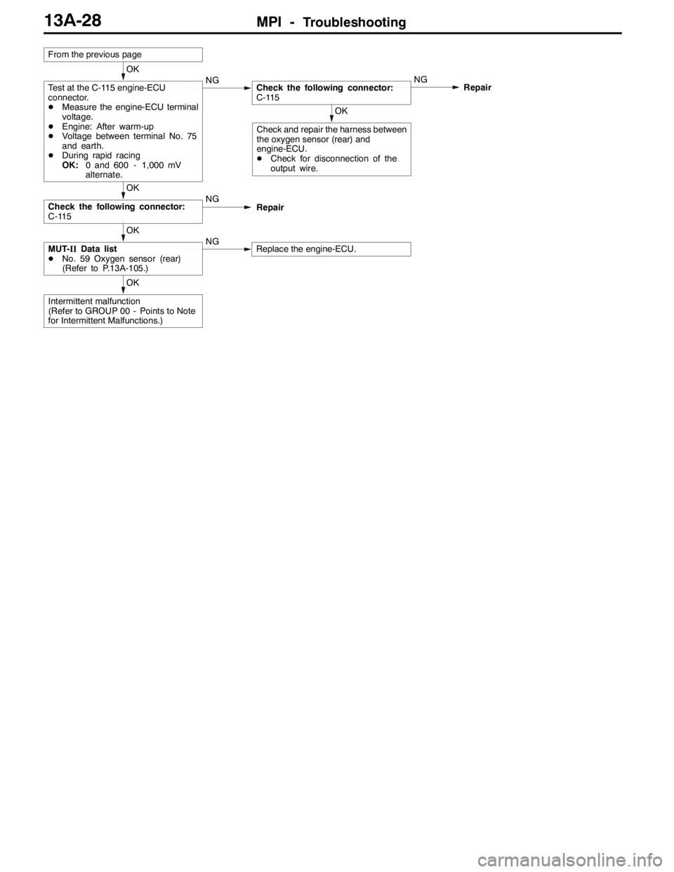
MPI -Troubleshooting13A-28
OK
Intermittent malfunction
(Refer to GROUP 00 - Points to Note
for Intermittent Malfunctions.)
OK
MUT-IIData list
DNo. 59 Oxygen sensor (rear)
(Refer to P.13A-105.)NGReplace the engine-ECU.
OK
Check the following connector:
C-115NG
Repair
OK
Check and repair the harness between
the oxygen sensor (rear) and
engine-ECU.
DCheck for disconnection of the
output wire.
OK
Test at the C-115 engine-ECU
connector.
DMeasure the engine-ECU terminal
voltage.
DEngine: After warm-up
DVoltage between terminal No. 75
and earth.
DDuring rapid racing
OK:0 and 600 - 1,000 mV
alternate.NGCheck the following connector:
C-115NG
Repair
From the previous page
Page 561 of 1449

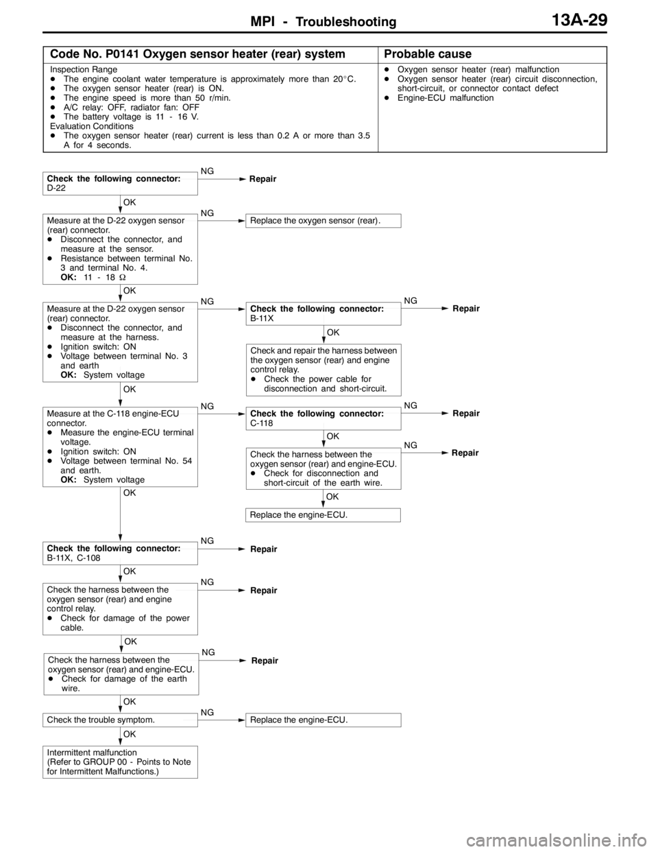
MPI -Troubleshooting13A-29
Code No. P0141 Oxygen sensor heater (rear) systemProbable cause
Inspection Range
DThe engine coolant water temperature is approximately more than 20_C.
DThe oxygen sensor heater (rear) is ON.
DThe engine speed is more than 50 r/min.
DA/C relay: OFF, radiator fan: OFF
DThe battery voltage is 11 - 16 V.
Evaluation Conditions
DThe oxygen sensor heater (rear) current is less than 0.2 A or more than 3.5
A for 4 seconds.DOxygen sensor heater (rear) malfunction
DOxygen sensor heater (rear) circuit disconnection,
short-circuit, or connector contact defect
DEngine-ECU malfunction
OK
Intermittent malfunction
(Refer to GROUP 00 - Points to Note
for Intermittent Malfunctions.)
OK
Check the trouble symptom.NGReplace the engine-ECU.
OK
Check the harness between the
oxygen sensor (rear) and engine-ECU.
DCheck for damage of the earth
wire.NG
Repair
OK
Check the harness between the
oxygen sensor (rear) and engine
control relay.
DCheck for damage of the power
cable.NG
Repair
OK
Check the following connector:
B-11X, C-108NG
Repair
OK
Replace the engine-ECU.NG
OK
Check the harness between the
oxygen sensor (rear) and engine-ECU.
DCheck for disconnection and
short-circuit of the earth wire.Repair
OK
Measure at the C-118 engine-ECU
connector.
DMeasure the engine-ECU terminal
voltage.
DIgnition switch: ON
DVoltage between terminal No. 54
and earth.
OK:System voltageNGCheck the following connector:
C-118NG
Repair
OK
Check and repair the harness between
the oxygen sensor (rear) and engine
control relay.
DCheck the power cable for
disconnection and short-circuit.
OK
Measure at the D-22 oxygen sensor
(rear) connector.
DDisconnect the connector, and
measure at the harness.
DIgnition switch: ON
DVoltage between terminal No. 3
and earth
OK:System voltageNGCheck the following connector:
B-11XNG
Repair
OK
Measure at the D-22 oxygen sensor
(rear) connector.
DDisconnect the connector, and
measure at the sensor.
DResistance between terminal No.
3 and terminal No. 4.
OK:11 - 1 8ΩNGReplace the oxygen sensor (rear).
Check the following connector:
D-22NG
Repair
Page 596 of 1449

MPI -Troubleshooting13A-64
OK
To the next page
OK
Measure at the C-39 engine-ECU connector.
DMeasure the engine-ECU terminal voltage.
DEngine: Idling
DA/C switch: ON (A/C compressor driven state)
DVoltage between terminal No .24 and earth
(A/C setting temperature: Minimum temperature)
(Air volume: Maximum)
OK:1 V or less
(A/C setting temperature: indoor temperature)
(Air volume: Minimum)
OK:System voltageNGCheck the Inspection Procedure 28: A/C load signal system.
(Refer to P.13A-95.)
NG
Replace the alternator.
OK
Check the trouble symptoms.OKIntermittent malfunction
(Refer to GROUP 00 - Points to Note
for Intermittent Malfunctions.) NG
OK
Check the harness between the
alternator and engine-ECU.
DCheck for disconnection,
short-circuit and damage of the
output cable.Repair
OK
Measure at the C-40 engine-ECU
connector.
DMeasure the engine-ECU terminal
voltage.
DEngine: Idling (after warm-up)
DRadiator fan: Stopped
DVoltage between terminal No. 33
and earth
OK:Voltage rises 0.2 to 3.5 V when
headlamp is turned OFF and
ON.
DVoltage between terminal No. 41
and earth
OK:Voltage drops whenheadlamp
is turned OFF and ON.NGCheck the following connectors:
C-40, B-21, B-03NG
Repair
OK
Check the harness between the
engine-ECU and earth joint.
DCheck for disconnection and
damage of the earth cable.
(2) NGCheck the following connector:
C-39NG
Repair
NG
Replace the engine-ECU.
OK
Check the trouble symptoms.OKIntermittent malfunction
(Refer to GROUP 00 - Points to Note
for Intermittent Malfunctions.) NG
OK
Check the harness between the
engine-ECU and battery.
DCheck for disconnection,
short-circuit and damage of the
power cable.Repair
OK
Measure at the C-115 and C-126
engine-ECU connectors.
DMeasure the engine-ECU terminal
voltage.
(1) Voltage between terminal No. 80
and earth
OK:System voltage
(2) Voltage between terminal No. 13
and earth
Voltage between terminal No. 26
and earth
(Ignition switch: ON)
OK:0.5 V or less(1) NGCheck the following connectors:
C-115, C-129, C-05, C-135NG
Repair
OK
MUT-IIData list
DNo. 59: Oxygen sensor (rear)
(Refer to P.13A-105.)NGCheck the Code No. P0136: Oxygen sensor (rear) system.
(Refer to P.13A-27.)
From the previous page