Page 427 of 1449

ENGINE -Camshaft and Camshaft Oil Seal11A-21
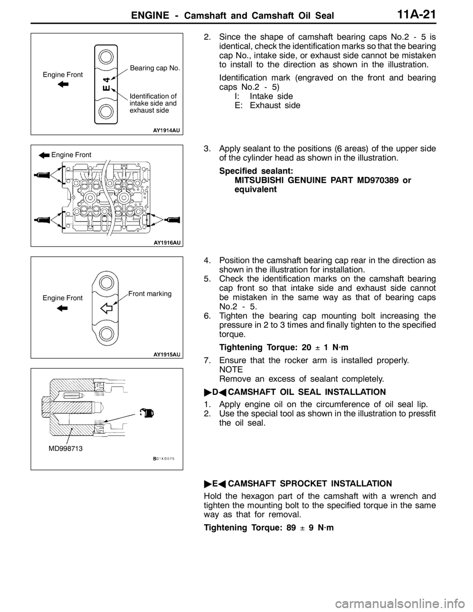
2. Since the shape of camshaft bearing caps No.2 - 5 is
identical, check the identification marks so that the bearing
cap No., intake side, or exhaust side cannot be mistaken
to install to the direction as shown in the illustration.
Identification mark (engraved on the front and bearing
caps No.2 - 5)
I: Intake side
E: Exhaust side
3. Apply sealant to the positions (6 areas) of the upper side
of the cylinder head as shown in the illustration.
Specified sealant:
MITSUBISHI GENUINE PART MD970389 or
equivalent
4. Position the camshaft bearing cap rear in the direction as
shown in the illustration for installation.
5. Check the identification marks on the camshaft bearing
cap front so that intake side and exhaust side cannot
be mistaken in the same way as that of bearing caps
No.2 - 5.
6. Tighten the bearing cap mounting bolt increasing the
pressure in 2 to 3 times and finally tighten to the specified
torque.
Tightening Torque: 20±1 N·m
7. Ensure that the rocker arm is installed properly.
NOTE
Remove an excess of sealant completely.
"DACAMSHAFT OIL SEAL INSTALLATION
1. Apply engine oil on the circumference of oil seal lip.
2. Use the special tool as shown in the illustration to pressfit
the oil seal.
"EACAMSHAFT SPROCKET INSTALLATION
Hold the hexagon part of the camshaft with a wrench and
tighten the mounting bolt to the specified torque in the same
way as that for removal.
Tightening Torque: 89±9 N·m
Engine FrontBearing cap No.
Identification of
intake side and
exhaust side
Engine Front
Front markingEngine Front
MD998713
Page 432 of 1449
ENGINE -Crankshaft Oil Seal11A-26
CRANKSHAFT OIL SEAL
REMOVAL AND INSTALLATION
Caution
If the vehicle is equipped with the Brembo disc brake, during maintenance, take care not to contact
the parts or tools to the caliper because the paint of caliper will be scratched.
1 2
34 5
6
Engine oil
(at the lip)
(at the lip)
3
6
132±5 N·m
Crankshaft Front Oil Seal Removal
Steps
DTiming belt and timing belt B
(Refer to P.11A-34.)
"DA1. Crankshaft sprocket B
2. Key
"CA3. Crankshaft front oil sealCrankshaft Rear Oil Seal Removal
Steps
DTransfer assembly
(Refer to GROUP 22A.)
DTransmission assembly
(Refer to GROUP 22A.)
DClutch cover, disc
AA""BA4. Flywheel bolt
5. Flywheel
"AA6. Crankshaft rear oil seal
Page 433 of 1449

ENGINE -Crankshaft Oil Seal11A-27
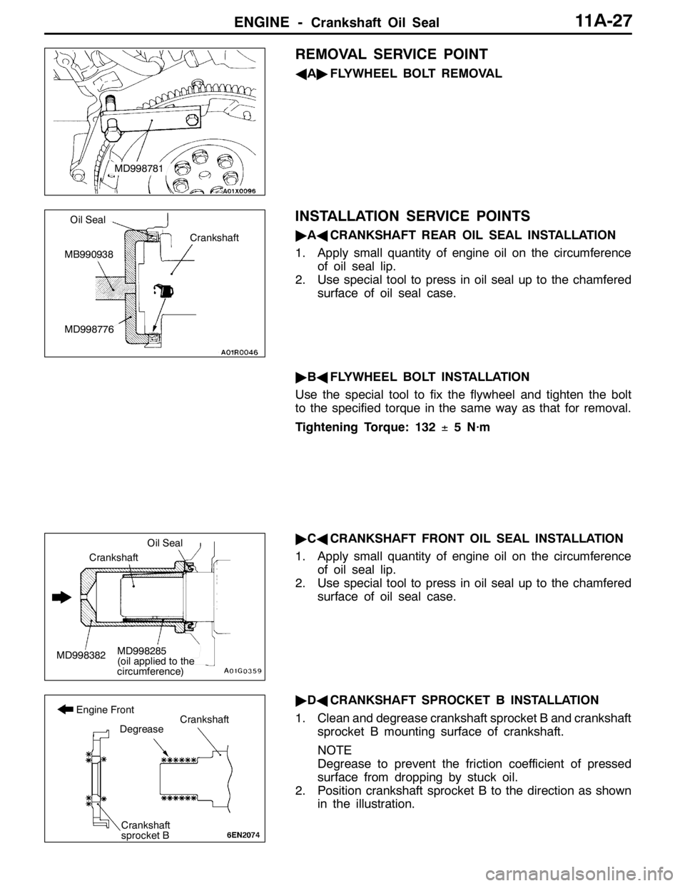
REMOVAL SERVICE POINT
AA"FLYWHEEL BOLT REMOVAL
INSTALLATION SERVICE POINTS
"AACRANKSHAFT REAR OIL SEAL INSTALLATION
1. Apply small quantity of engine oil on the circumference
of oil seal lip.
2. Use special tool to press in oil seal up to the chamfered
surface of oil seal case.
"BAFLYWHEEL BOLT INSTALLATION
Use the special tool to fix the flywheel and tighten the bolt
to the specified torque in the same way as that for removal.
Tightening Torque: 132±5 N·m
"CACRANKSHAFT FRONT OIL SEAL INSTALLATION
1. Apply small quantity of engine oil on the circumference
of oil seal lip.
2. Use special tool to press in oil seal up to the chamfered
surface of oil seal case.
"DACRANKSHAFT SPROCKET B INSTALLATION
1. Clean and degrease crankshaft sprocket B and crankshaft
sprocket B mounting surface of crankshaft.
NOTE
Degrease to prevent the friction coefficient of pressed
surface from dropping by stuck oil.
2. Position crankshaft sprocket B to the direction as shown
in the illustration.
MD998781
Crankshaft
Oil Seal
MB990938
MD998776
MD998382
Oil Seal
Crankshaft
MD998285
(oil applied to the
circumference)
Crankshaft
sprocket B
Degrease
Engine FrontCrankshaft
Page 443 of 1449

ENGINE -Timing Belt and Timing Belt B11A-37
(1) Connect the special tool (MB991668) to the MUT-II.
(2) Connect the special tool (MB991704) to the MUT-II
and the battery.
(3) Rotate the crankshaft clockwise for two rounds to
position No.1 cylinder at compression TDC and check
that timing marks of each sprocket are aligned with
each other.
(4) Select “Belt Tension Measurement” from the menu
screen of the MUT-II.
(5) Hold the special tool (MB991668) to the middle of
the belt between sprockets (at the place indicated
by the arrow) as shown in the illustration about 10
- 20 mm away from the rear surface of the belt and
so that it is perpendicular to the belt (within an angle
of±15_).
(6) Gently tap the middle of the belt between sprockets
(the place indicated by the arrow) with your finger
as shown in the illustration and check that the vibration
frequency of the belt is within the standard value.
Caution
1) If strong gusts of wind blow against the
microphone or if there are any loud sources
of noise nearby, the values measured by the
microphone may not correspond to actual
values.
2) If the microphone is touching the belt while
the measurement is being made, the values
measured by the microphone may not
correspond to actual values.
Apply a force of approx.100N to the middle (arrow part)
of pulley shown in the figure, and check that the deflection
is within the standard value.
3. If it is outside the standard value, re-adjust belt tension.
MB991668
10 - 20 mm
15_
15_
Gently tap with
your finger
Deflection
Approx.
100 N
Page 446 of 1449

ENGINE -Timing Belt and Timing Belt B11A-40
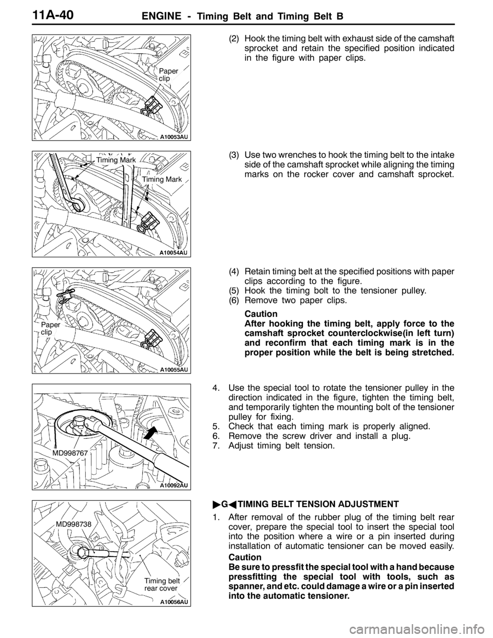
(2) Hook the timing belt with exhaust side of the camshaft
sprocket and retain the specified position indicated
in the figure with paper clips.
(3) Use two wrenches to hook the timing belt to the intake
side of the camshaft sprocket while aligning the timing
marks on the rocker cover and camshaft sprocket.
(4) Retain timing belt at the specified positions with paper
clips according to the figure.
(5) Hook the timing bolt to the tensioner pulley.
(6) Remove two paper clips.
Caution
After hooking the timing belt, apply force to the
camshaft sprocket counterclockwise(in left turn)
and reconfirm that each timing mark is in the
proper position while the belt is being stretched.
4. Use the special tool to rotate the tensioner pulley in the
direction indicated in the figure, tighten the timing belt,
and temporarily tighten the mounting bolt of the tensioner
pulley for fixing.
5. Check that each timing mark is properly aligned.
6. Remove the screw driver and install a plug.
7. Adjust timing belt tension.
"GATIMING BELT TENSION ADJUSTMENT
1. After removal of the rubber plug of the timing belt rear
cover, prepare the special tool to insert the special tool
into the position where a wire or a pin inserted during
installation of automatic tensioner can be moved easily.
Caution
Be sure to pressfit the special tool with a hand because
pressfitting the special tool with tools, such as
spanner, and etc. could damage a wire or a pin inserted
into the automatic tensioner.
Paper
clip
Timing Mark
Timing Mark
Paper
clip
MD998767
MD998738
Timing belt
rear cover
Page 453 of 1449

ENGINE -Engine Assembly11A-47
AD"ENGINE ASSEMBLY REMOVAL
After checking that all the cables, hoses, and harness
connectors have been disconnected, lift the engine with a
chain block slowly and remove the engine assembly located
at the upper engine room.
INSTALLATION SERVICE POINTS
"AAENGINE ASSEMBLY INSTALLATION
Install the engine assembly while checking that none of cables,
hoses, or harness connectors, etc. has been engaged.
"BAENGINE MOUNTING BRACKET AND STOPPER
ASSEMBLY INSTALLATION
1. Support the engine oil pan with a garage jack via a block
of wood cut adjusting the engine position and install the
engine mounting bracket and stopper assembly. Position
the engine mounting stopper so that a mark indicated
by an arrow can face the direction shown in the illustration.
2. Support engine with garage jack.
3. Remove the chain block and hold the engine assembly
with the special tool.(Tool used for removal of transmission
assembly)
"CAO-RING/FUEL HIGH PRESSURE HOSE
INSTALLATION
1. Apply small quantity of new engine oil on O-ring.
Caution
Do not let engine oil get into the delivery pipe.
2. Install the fuel high pressure pipe to the delivery pipe
rotating in both directions without damaging the O-ring
and check that it rotates smoothly.
3. In case of not rotating smoothly, remove the fuel high
pressure hose and insert it to the delivery pipe again
after checking damage of the O-ring since there is a
possibility of O-ring engagement.
4. Tighten fuel high pressure hose mounting bolt to the
specified torque.
Tightening Torque: 5.0±1.0 N·m
Engine mounting stopper
Engine side
Engine side
Page 461 of 1449

ENGINE OVERHAUL -Specifications11B-7
Items Tightening torque N·m
Water outlet fitting bolt10±1
Thermostat housing bolt23±4
Water inlet pipe bolt (M6)10±1
Water inlet pipe bolt (M8)13±2
Water pump bolt14±1
Knock sensor23±2
Rocker arm, camshaft
Cam position sensor bolt8.8±1.0
Cover bolt10±2
Cam position sensing cylinder bolt22±4
Cam position sensor support bolt14±1
Bearing cap bolt20±1
Oil delivery body bolt11±1
Cylinder head, valve
Cylinder head bolt78±2→Completely loosen→20±2→90_+90_
Oil pump, oil pan
Drain plug39±5
Oil pan bolt9±3
Oil screen bolt19±3
Baffle plate bolt22±4
Oil pressure switch19±3
Oil cooler bypass valve54±5
Relief plug44±5
Oil filter bracket bolt19±3
Plug cap23±3
Flange bolt36±3
Oil pump case bolt23±3
Oil pump cover bolt17±1
Oil pump cover screw10±2
Piston, connecting rod
Connecting rod cap nut20±2+90_-94_
Crankshaft, cylinder block
Flywheel bolt132±5
Rear plate bolt11±1
Bell housing cover bolt9±1
Rear oil seal case bolt11±1
Beam bearing cap bolt25±2+90_- 100_
Check valve32±2
Throttle body
Throttle position sensor bolt2.0±0.5
Turbocharger
Waste gate actuator bolt11.3±1.5
Page 465 of 1449
ENGINE OVERHAUL -Special Tools11B-11
Tool UseName Number
MD998372Silent shaft bearing
pullerRemoval of counter balance shaft rear bearing
MB991603Silent shaft
bearing installer
stopperGuide stopper when removing/pressing in
counter balance shaft rear bearing
MD998705Silent shaft bearing
installerPress in of counter balance shaft front and rear
bearings
MD998375Crankshaft front oil
seal installerInstallation of crankshaft front oil seal
MD998285Crankshaft front oil
seal guideGuide for installation of crankshaft front oil seal
MD998780Piston pin setting
toolRemoval/press in of piston pin
MD998776Crankshaft rear oil
seal installerInstallation of crankshaft rear oil seal
MD990938HandleInstallation of crankshaft rear oil seal
(Use together with MD998776.)