Page 467 of 1449

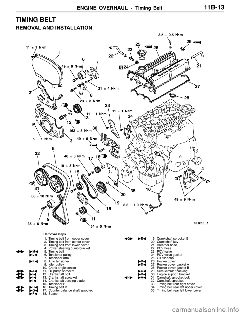
ENGINE OVERHAUL -Timing Belt11B-13
TIMING BELT
REMOVAL AND INSTALLATION
1
11±1N•m
2
3
4 56
7
8
910
11 1213
14 15
16 1718
192021 2223
2425
26
27
2829
30
313233
34
35
49±6N•m
21±4N•m
23±3N•m
11±1N•m11±1N•m
88±10 N•m
35±6N•m
54±5N•m 19±3N•m 46±3N•m 9±1N•m162±5N•m3.5±0.5 N•m
49±9N•m
8.8±1.0 N•m 49±5N•m
Removal steps
1. Timing belt front upper cover
2. Timing belt front center cover
3. Timing belt front lower cover
4. Power steering pump bracket
AA""MA5. Timing belt
"LA6. Tensioner pulley
7. Tensioner arm
"KA8. Auto tensioner
9. Idler pulley
10. Crank angle sensor
AB""JA11. Oil pump sprocket
AC""IA12. Crankshaft bolt
AD""IA13. Crankshaft sprocket
"IA14. Crankshaft sensing blade
15. Tensioner B
AE""HA16. Timing belt B
AF""GA17. Counter balance shaft sprocket
"FA18. SpacerAG""EA19. Crankshaft sprocket B
20. Crankshaft key
21. Breather hose
22. PCV hose
23. PCV valve
24. PCV valve gasket
25. Oil filler cap
"DA26. Rocker cover
"DA27. Rocker cover gasket A
28. Rocker cover gasket B
"CA29. Semi-circular packing
"BA30. Engine support bracket
AH""AA31. Camshaft sprocket bolt
32. Camshaft sprocket
33. Timing belt rear right cover
34. Timing belt rear left upper cover
35. Timing belt rear left lower cover
Page 488 of 1449
ENGINE OVERHAUL -Rocker Arm and Camshaft11B-34
ROCKER ARM AND CAMSHAFT
REMOVAL AND INSTALLATION
1 2 3
4
5 6
78
910
111213
10±2N•m
14±1N•m
22±4N•m
11±1N•m
8.8±1.0 N•m
20±1N•m
14
15
16
Apply engine oil on
all sliding sections
before installing.
17
Removal steps
1. Cam position sensor
2. O-ring
3. Cover
4. Gasket
"FA5. Cam position sensing cylinder
"EA6. Cam position sensor support
"DA7. Camshaft oil seal
"CA8. Bearing cap, rear
"CA9. Bearing cap, front"CA10. Bearing cap No. 5
"CA11. Bearing cap No. 2
"CA12. Bearing cap No. 3
"CA13. Bearing cap No. 4
"BA14. Camshaft
15. Rocker arm
AA""AA16. Lash adjuster
17. Oil delivery body
Page 501 of 1449

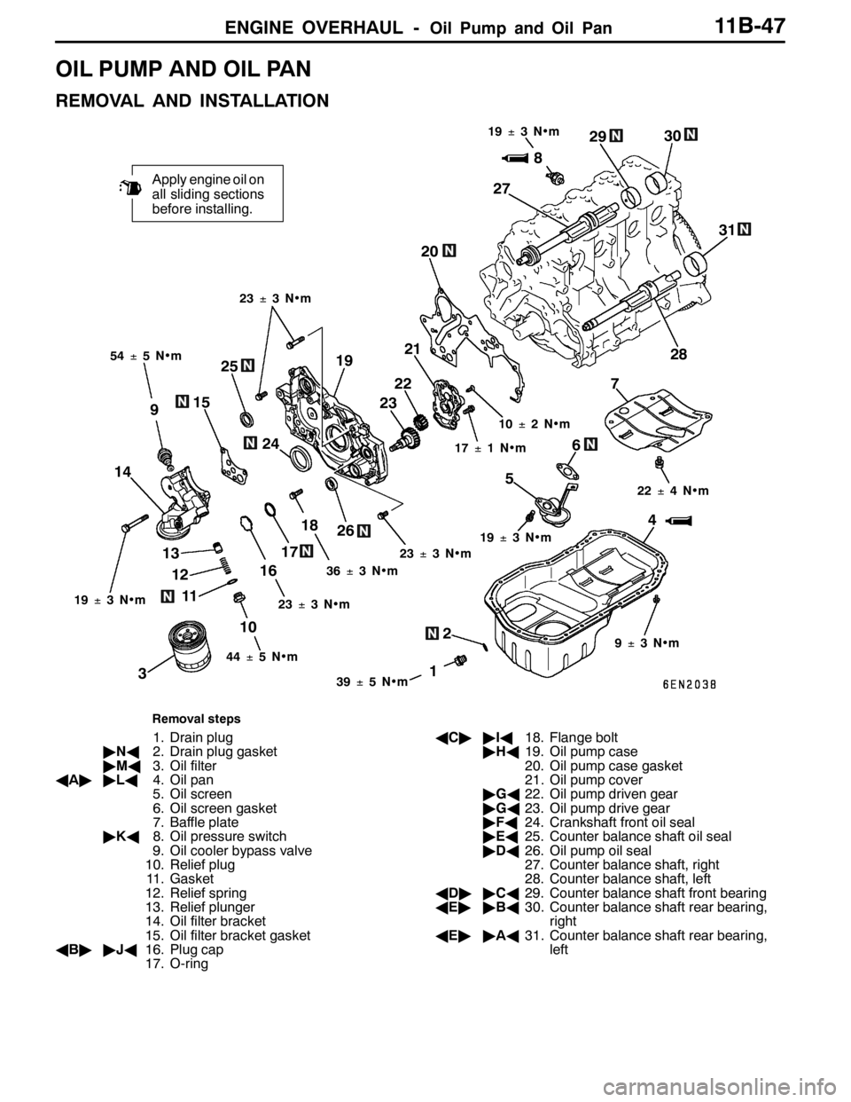
ENGINE OVERHAUL -Oil Pump and Oil Pan11B-47
OIL PUMP AND OIL PAN
REMOVAL AND INSTALLATION
2
1
Apply engine oil on
all sliding sections
before installing.
4 56
12 13
16187 20
38
9
10 1415
1719
1139±5N•m 54±5N•m19±3N•m
36±3N•m23±3N•m 17±1N•m 10±2N•m
9±3N•m 22±4N•m 23±3N•m
19±3N•m
44±5N•m 23±3N•m
25
24232221
26272930
31
28
19±3N•m
Removal steps
1. Drain plug
"NA2. Drain plug gasket
"MA3. Oil filter
AA""LA4. Oil pan
5. Oil screen
6. Oil screen gasket
7. Baffle plate
"KA8. Oil pressure switch
9. Oil cooler bypass valve
10. Relief plug
11. Gasket
12. Relief spring
13. Relief plunger
14. Oil filter bracket
15. Oil filter bracket gasket
AB""JA16. Plug cap
17. O-ringAC""IA18. Flange bolt
"HA19. Oil pump case
20. Oil pump case gasket
21. Oil pump cover
"GA22. Oil pump driven gear
"GA23. Oil pump drive gear
"FA24. Crankshaft front oil seal
"EA25. Counter balance shaft oil seal
"DA26. Oil pump oil seal
27. Counter balance shaft, right
28. Counter balance shaft, left
AD""CA29. Counter balance shaft front bearing
AE""BA30. Counter balance shaft rear bearing,
right
AE""AA31. Counter balance shaft rear bearing,
left
Page 502 of 1449

ENGINE OVERHAUL -Oil Pump and Oil Pan11B-48
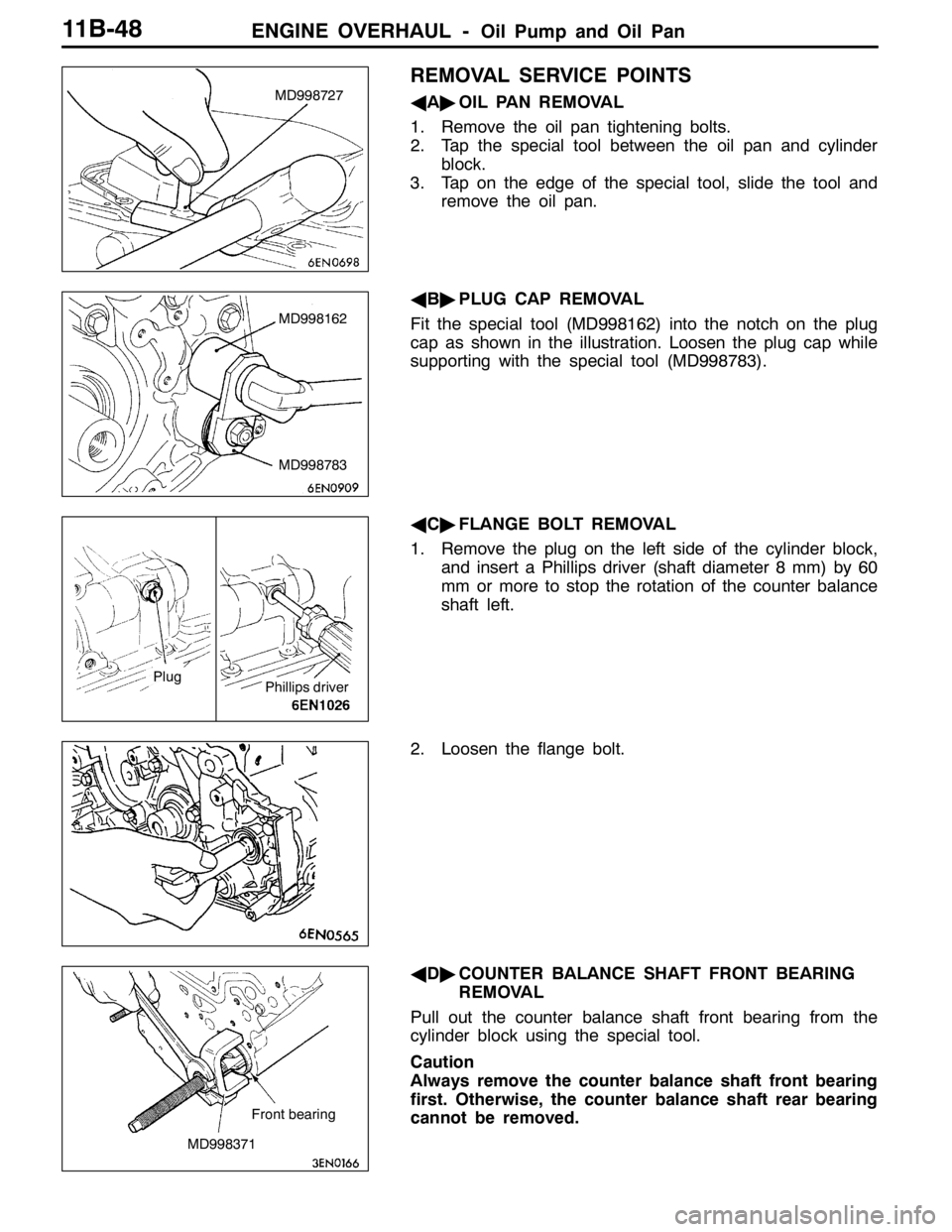
REMOVAL SERVICE POINTS
AA"OIL PAN REMOVAL
1. Remove the oil pan tightening bolts.
2. Tap the special tool between the oil pan and cylinder
block.
3. Tap on the edge of the special tool, slide the tool and
remove the oil pan.
AB"PLUG CAP REMOVAL
Fit the special tool (MD998162) into the notch on the plug
cap as shown in the illustration. Loosen the plug cap while
supporting with the special tool (MD998783).
AC"FLANGE BOLT REMOVAL
1. Remove the plug on the left side of the cylinder block,
and insert a Phillips driver (shaft diameter 8 mm) by 60
mm or more to stop the rotation of the counter balance
shaft left.
2. Loosen the flange bolt.
AD"COUNTER BALANCE SHAFT FRONT BEARING
REMOVAL
Pull out the counter balance shaft front bearing from the
cylinder block using the special tool.
Caution
Always remove the counter balance shaft front bearing
first. Otherwise, the counter balance shaft rear bearing
cannot be removed.MD998727
MD998162
MD998783
Plug
Phillips driver
MD998371Front bearing
Page 503 of 1449

ENGINE OVERHAUL -Oil Pump and Oil Pan11B-49
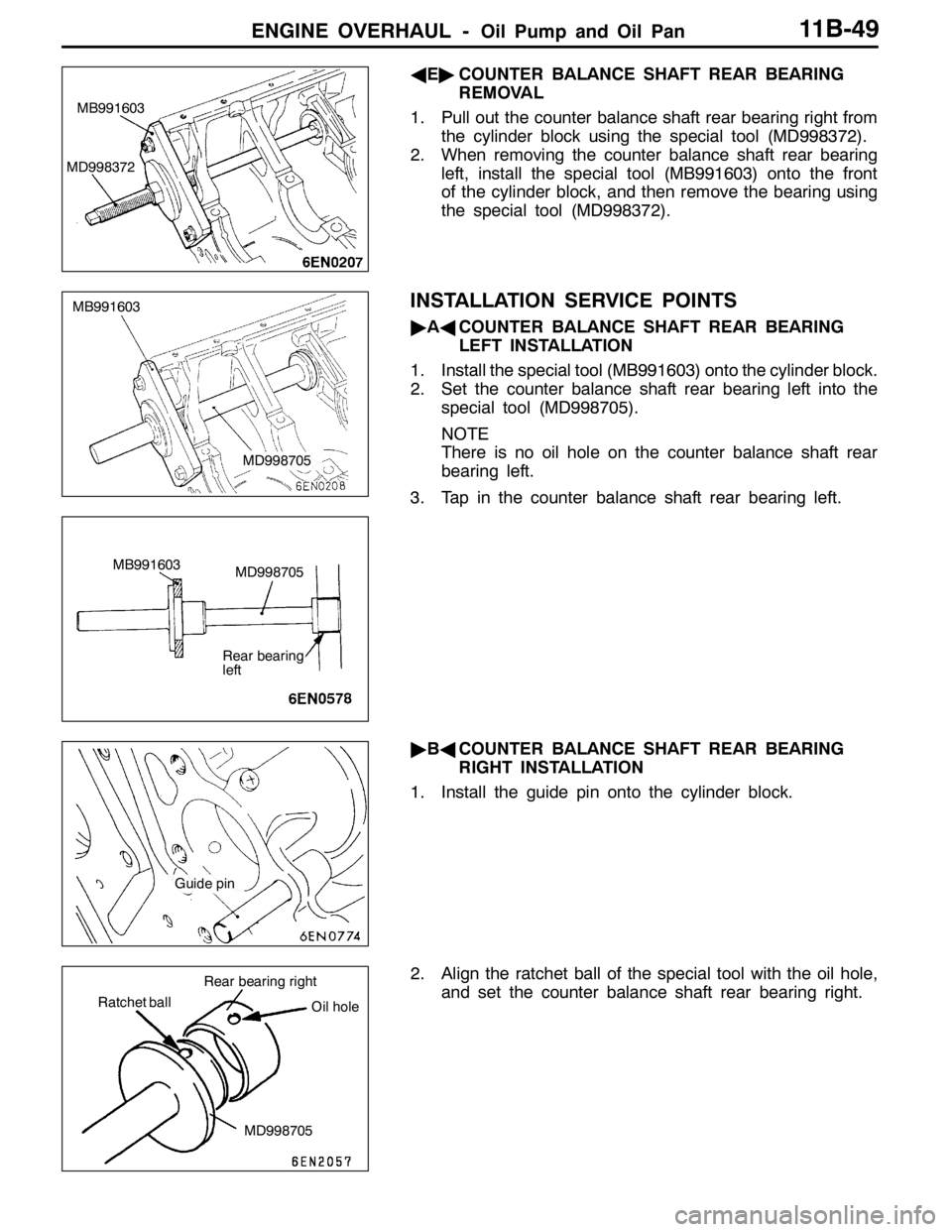
AE"COUNTER BALANCE SHAFT REAR BEARING
REMOVAL
1. Pull out the counter balance shaft rear bearing right from
the cylinder block using the special tool (MD998372).
2. When removing the counter balance shaft rear bearing
left, install the special tool (MB991603) onto the front
of the cylinder block, and then remove the bearing using
the special tool (MD998372).
INSTALLATION SERVICE POINTS
"AACOUNTER BALANCE SHAFT REAR BEARING
LEFT INSTALLATION
1. Install the special tool (MB991603) onto the cylinder block.
2. Set the counter balance shaft rear bearing left into the
special tool (MD998705).
NOTE
There is no oil hole on the counter balance shaft rear
bearing left.
3. Tap in the counter balance shaft rear bearing left.
"BACOUNTER BALANCE SHAFT REAR BEARING
RIGHT INSTALLATION
1. Install the guide pin onto the cylinder block.
2. Align the ratchet ball of the special tool with the oil hole,
and set the counter balance shaft rear bearing right.
MB991603
MD998372
MB991603
MD998705
MB991603
MD998705
Rear bearing
left
Guide pin
Ratchet ball
MD998705 Rear bearing right
Oil hole
Page 504 of 1449
ENGINE OVERHAUL -Oil Pump and Oil Pan11B-50
3. Align and insert the special tool into the guide pin, and
tap in the counter balance shaft rear bearing right.
"CACOUNTER BALANCE SHAFT FRONT BEARING
INSTALLATION
1. Remove the part for tapping in the rear bearing from
the special tool.
2. Install the guide pin onto the cylinder block.
3. Align the ratchet ball of the special tool with the oil hole,
and set the counter balance shaft front bearing.
MD998705
Guide pin
MD998705
Part for tapping in
the rear bearing
Guide pin
Ratchet ball
MD998705 Front bearing
Oil hole
Page 518 of 1449
ENGINE OVERHAUL -Crankshaft and Cylinder Block11B-64
CRANKSHAFT AND CYLINDER BLOCK
REMOVAL AND INSTALLATION
25±2N•m+90_- 100_
21
Apply engine oil on
all sliding sections
before installing.
4
5 6
73
8 9 1011
132±5N•m 11±1N•m
11±1N•m9±1N•m
32±2N•m
14
1312 15
Removal steps
1. Flywheel bolt
2. Flywheel
3. Rear plate
4. Bell housing cover
"EA5. Rear oil seal case
"DA6. Rear oil seal
"CA7. Bearing cap bolt
"CA8. Beam bearing cap"BA9. Crankshaft bearing lower
10. Crankshaft
"BA11. Crankshaft bearing upper
"AA12. Thrust bearing
13. Check valve
14. Oil jet
15. Cylinder block
Page 521 of 1449
ENGINE OVERHAUL -Crankshaft and Cylinder Block11B-67
8. After installing the beam bearing cap, inspect the end
play of the crankshaft. If the end play exceeds the limit
value, replace the crankshaft bearing.
Standard value: 0.05 - 0.25 mm
Limit value: 0.4 mm
"DAREAR OIL SEAL INSTALLATION
Press in the rear oil seal using the special tool.
"EAREAR OIL SEAL CASE INSTALLATION
1. Apply form-in-place gasket onto the rear oil seal case
at the position shown in the illustration.
Form-in-place gasket
Specified gasket:
Mitsubishi Genuine Part No. MD970389 or
equivalent
Caution
Evenly squeeze out the form-in-place gasket so that
it is not insufficient or excessive.
2. Apply an appropriate amount of engine oil on the entire
periphery of the oil seal lip, and install on the cylinder
block.
MB990938
MD998776