Page 697 of 1449
![MITSUBISHI LANCER EVOLUTION 2007 Service Repair Manual ENGINE COOLING -On-vehicle Service14-9
5. Connect the special tool (MB991658) to the harness side
of the engine coolant temperature sensor connector.
6. Connect the special tool [MB991791(APS)] to the MITSUBISHI LANCER EVOLUTION 2007 Service Repair Manual ENGINE COOLING -On-vehicle Service14-9
5. Connect the special tool (MB991658) to the harness side
of the engine coolant temperature sensor connector.
6. Connect the special tool [MB991791(APS)] to the](/manual-img/19/57084/w960_57084-696.png)
ENGINE COOLING -On-vehicle Service14-9
5. Connect the special tool (MB991658) to the harness side
of the engine coolant temperature sensor connector.
6. Connect the special tool [MB991791(APS)] to the special
tool (MB991658).
7. Start the engine and let it run at idle.
NOTE
Since the resistance value of the special tool (APS)
indicates a low engine coolant temperature, engine speed
increases.
8. When the lever of the special tool (APS) is turned to
the end, check that the engine speed decreases and
the radiator fan motor rotates.
9. When the lever of the special tool (APS) is turned to
the reverse direction, check that the voltage between
terminals of the radiator fan motor connector gradually
decreases from the battery voltage to 0 V.
10. If inoperable, replace the radiator fan controller.
(Refer to P.14-15.)
11. Install the center under cover.
(Refer to GROUP 51 - Front Bumper.)
12. Connect the engine coolant temperature sensor
connector.
1. Remove the center under cover.
(Refer to GROUP 51 - Front Bumper.)
2. Insert the special tool at the back of the radiator fan
motor connector.
3. Connect the special tool to the circuit tester.
4. Start the engine and run it at idle.
5. Turn the A/C switch to the ON position and hold the
engine coolant temperature at 80_C or lower.
6. When the voltage between the terminals of the radiator
fan motor connector, the following values of (1) - (3)
can be detected at random.
(1) 0 V
(2) 8.22.6 V
(3) Battery voltage2.6 V
7. If inoperable, replace the radiator fan controller.
(Refer to P.14-15.)
8. Install the center under cover.
(Refer to GROUP 51 - Front Bumper.)
Engine coolant
temperature sensor
connector
(harness side)
MB991791(APS)
MB991658
MB991658Lever
MB991791(APS)
Radiator fan
controller
MB991222
Circuit tester
Connector
rear view
Page 745 of 1449
ENGINE ELECTRICAL -Charging System16-13
DISASSEMBLY AND REASSEMBLY
1
23
4 7654
891012
111314
Disassembly steps
AA"1. Front bracket assembly
AB"2. Alternator pulley
"BA3. Rotor
4. Rear bearing
5. Bearing retainer
6. Front bearing
7. Front bracketAC"8. Stator
9. Plate
AC""AA10. Regulator assembly
11. Brush
12. Packing
13. Rectifier
14. Rear bracket
Page 746 of 1449

ENGINE ELECTRICAL -Charging System16-14
DISASSEMBLY SERVICE POINTS
AA"FRONT BRACKET ASSEMBLY REMOVAL
Insert a flat tip screwdrivers or the like in the clearance between
the front bracket assembly and stator core, to pry open and
separate the stator and front bracket.
Caution
Do not insert a screwdriver too far, or the stator coil gets
damaged.
AB"ALTERNATOR PULLEY REMOVAL
Face pulley side upward, fix the rotor with a work bench
and remove the pulley.
Caution
Use care not to damage the rotor.
AC"STATOR/REGULATOR ASSEMBLY REMOVAL
1. Unsolder the stator with a soldering iron (180 to 250
W). Complete this work within four seconds not to transfer
heat to the diode.
2. When removing rectifier from the regulator assembly,
remove the soldered sections to rectifier.
Caution
(1) Use care to make sure that the heat of the soldering
iron is not transmitted to the diodes for a long period.
(2) Use care that no undue force is exerted to the
lead wires of the diodes.
REASSEMBLY SERVICE POINTS
"AAREGULATOR ASSEMBLY INSTALLATION
After installing the regulator assembly, insert a wire into the
hole provided on the rear bracket while pressing in the brush
to fix the brush.
NOTE
The brush is fixed when a wire is inserted, making rotor
installation easier.
SolderedRectifier
assembly
Soldered
Wire
Rear bracket
BrushWire
Page 753 of 1449
ENGINE ELECTRICAL -Starting System16-21
DISASSEMBLY AND REASSEMBLY
1 1713
1512
4 3
211
6 1614
1098
7 5
182021
19
22
Disassembly steps
1. Cover
2. Screw
AA"3. Magnetic switch
4. Screw
5. Through
6. Rear bracket
7. Brush holder
8. Rear bearing
AB"9. Armature
10. Yoke assembly
AB"11. Ball12. Packing A
13. Packing B
14. Plate
15. Planetary gear
16. Lever
AC""AA17. Snap ring
AC""AA18. Stop ring
19. Overrunning clutch
20. Internal gear
21. Planetary gear holder
22. Front bracket
Page 756 of 1449

ENGINE ELECTRICAL -Starting System16-24
OVERRUNNING CLUTCH CHECK
1. While holding clutch housing, rotate the pinion. Drive
pinion should rotate smoothly in one direction, but should
not rotate in opposite direction. If clutch does not function
properly, replace overrunning clutch assembly.
2. Inspect pinion for wear or burrs. If pinion is worn or burred,
replace overrunning clutch assembly. If pinion is damaged,
also inspect ring gear for wear or burrs.
FRONT AND REAR BRACKET BUSHING CHECK
Inspect bushing for wear or burrs. If bushing is worn or burred,
replace front bracket assembly or rear bracket assembly.
BRUSH REPLACEMENT
1. Check the surface contacting the commutator for
roughness and the brush length.
Limit value: 7.0 mm
2. If the limit is exceeded, replace the brush holder.
ARMATURE TEST
ARMATURE COIL SHORT-CIRCUIT TEST
1. Check that the armature coil is not grounded.
2. Place armature in a growler.
3. Hold a thin steel blade parallel and just above while rotating
armature slowly in growler. A shorted armature will cause
blade to vibrate and be attracted to the core. Replace
shorted armature.
ARMATURE COIL EARTH TEST
Check the insulation between each commutator segment and
armature coil core.
If there is no continuity, the insulation is in order.
Free
Lock
Length
Growler
Page 775 of 1449
ENGINE AND EMISSION CONTROL -Emission Control System17-5
SERVICE SPECIFICATIONS
ItemsStandard value
Purge control solenoid valve coil resistance (at 20_C)Ω30 - 34
EGR control solenoid valve coil resistance (at 20_C)Ω29 - 35
VACUUM HOSE
VACUUM HOSE PIPING DIAGRAM
Fuel
pressure
control
solenoid
valve
Oxygen
sensor
(front)
Check
valve
Fuel
pressure
regulator
PCV valve To
fuel tank
Oxygen sensor (rear) From
fuel pump
Air
inletEGR control
solenoid valve
Purge
control
solenoid
valveCanisterFrom
fuel tank
EGR
valve Injector
Three - way
catalytic converter A
P
E
Page 818 of 1449

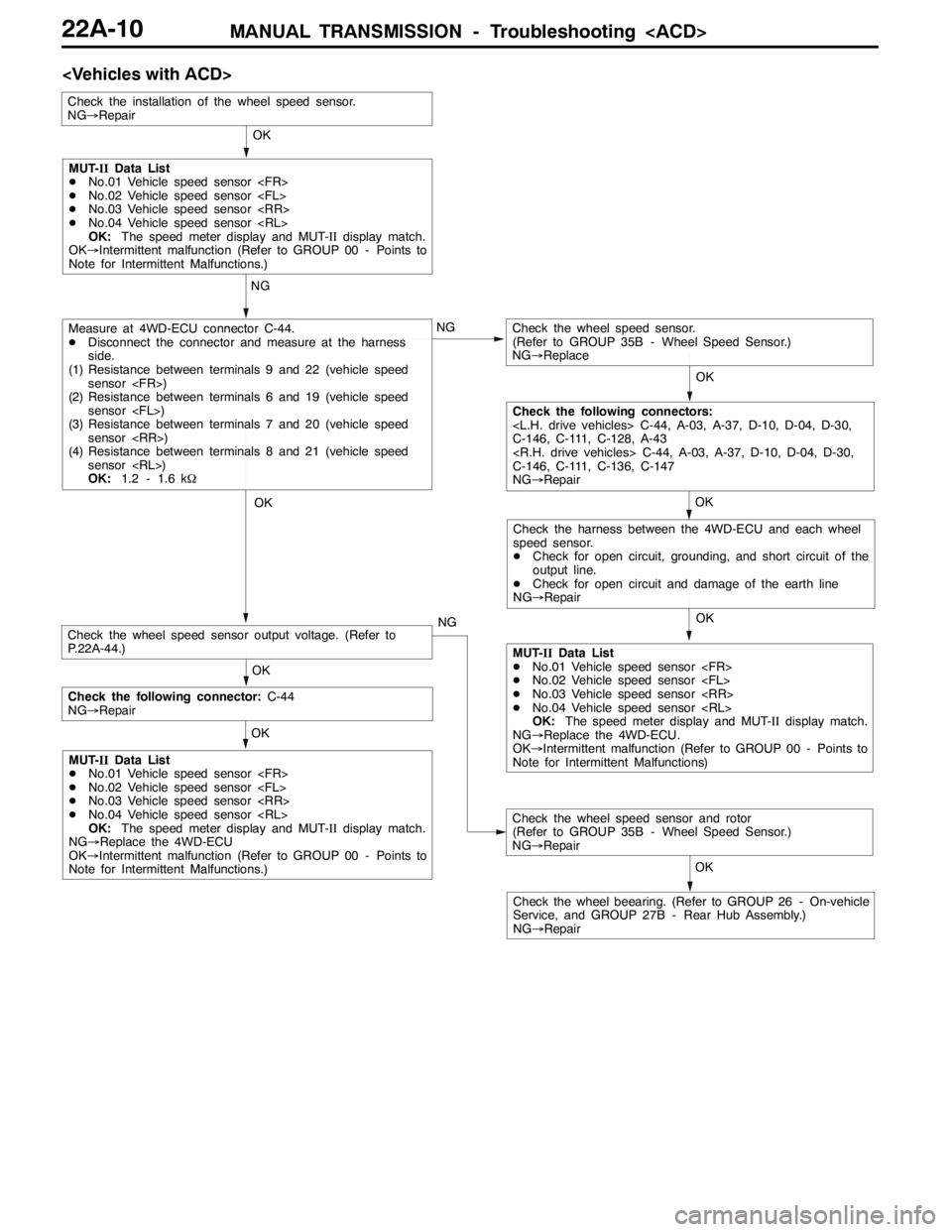
MANUAL TRANSMISSION - Troubleshooting 22A-10
OK OK NG
OK NG
OK OK
OK
NG
Measure at 4WD-ECU connector C-44.
DDisconnect the connector and measure at the harness
side.
(1) Resistance between terminals 9 and 22 (vehicle speed
sensor )
(2) Resistance between terminals 6 and 19 (vehicle speed
sensor )
(3) Resistance between terminals 7 and 20 (vehicle speed
sensor )
(4) Resistance between terminals 8 and 21 (vehicle speed
sensor )
OK:1.2 - 1.6 kΩCheck the wheel speed sensor.
(Refer to GROUP 35B - Wheel Speed Sensor.)
NG→Replace
Check the installation of the wheel speed sensor.
NG→Repair
Check the wheel speed sensor and rotor
(Refer to GROUP 35B - Wheel Speed Sensor.)
NG→Repair
Check the wheel beearing. (Refer to GROUP 26 - On-vehicle
Service, and GROUP 27B - Rear Hub Assembly.)
NG→RepairOK
MUT-IIData List
DNo.01 Vehicle speed sensor
DNo.02 Vehicle speed sensor
DNo.03 Vehicle speed sensor
DNo.04 Vehicle speed sensor
OK:The speed meter display and MUT-IIdisplay match.
OK→Intermittent malfunction (Refer to GROUP 00 - Points to
Note for Intermittent Malfunctions.)
Check the following connectors:
C-44, A-03, A-37, D-10, D-04, D-30,
C-146, C-111, C-128, A-43
C-44, A-03, A-37, D-10, D-04, D-30,
C-146, C-111, C-136, C-147
NG→Repair
Check the harness between the 4WD-ECU and each wheel
speed sensor.
DCheck for open circuit, grounding, and short circuit of the
output line.
DCheck for open circuit and damage of the earth line
NG→Repair
MUT-IIData List
DNo.01 Vehicle speed sensor
DNo.02 Vehicle speed sensor
DNo.03 Vehicle speed sensor
DNo.04 Vehicle speed sensor
OK:The speed meter display and MUT-IIdisplay match.
NG→Replace the 4WD-ECU.
OK→Intermittent malfunction (Refer to GROUP 00 - Points to
Note for Intermittent Malfunctions) OK
Check the following connector:C-44
NG→Repair
MUT-IIData List
DNo.01 Vehicle speed sensor
DNo.02 Vehicle speed sensor
DNo.03 Vehicle speed sensor
DNo.04 Vehicle speed sensor
OK:The speed meter display and MUT-IIdisplay match.
NG→Replace the 4WD-ECU
OK→Intermittent malfunction (Refer to GROUP 00 - Points to
Note for Intermittent Malfunctions.)
Check the wheel speed sensor output voltage. (Refer to
P.22A-44.)
Page 819 of 1449

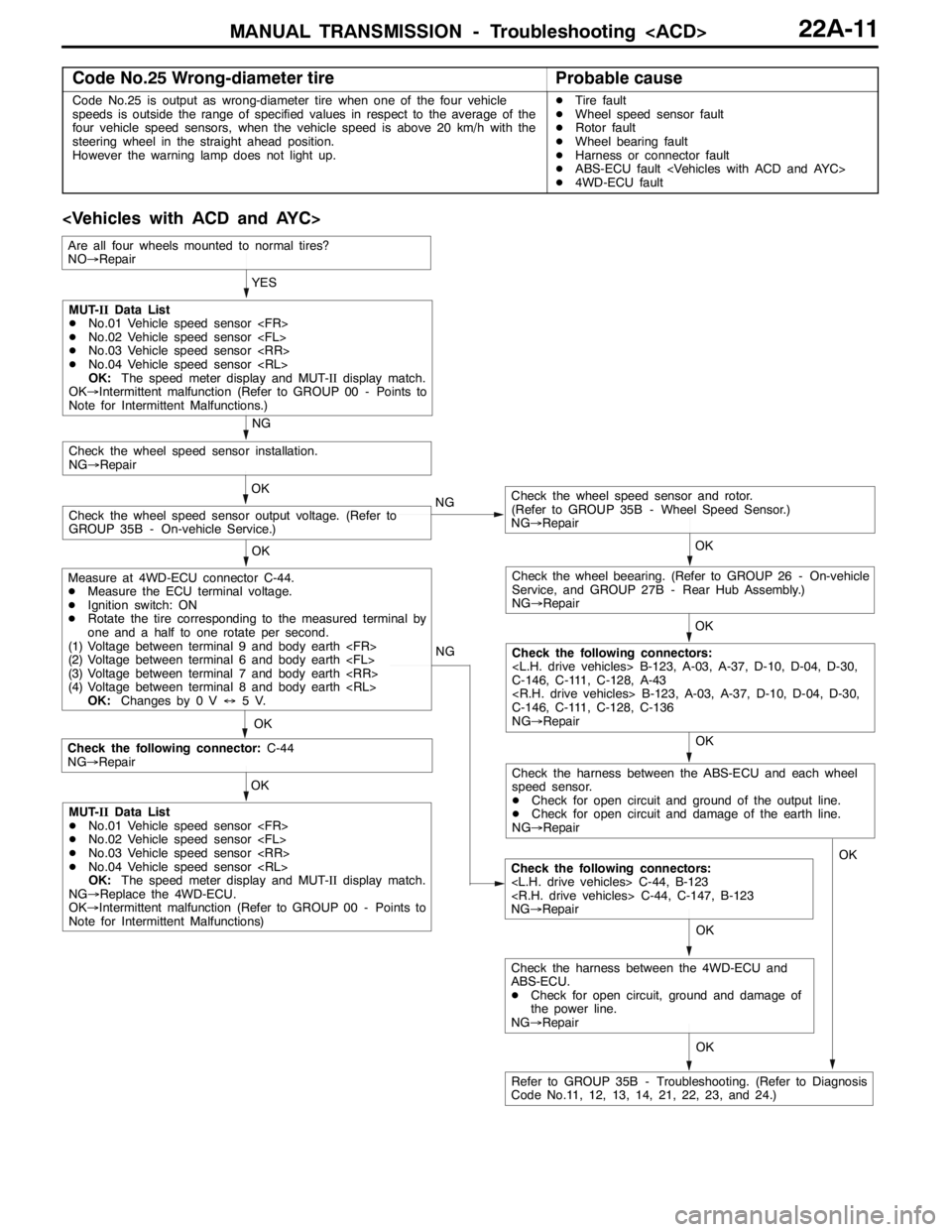
MANUAL TRANSMISSION - Troubleshooting 22A-11
Code No.25 Wrong-diameter tireProbable cause
Code No.25 is output as wrong-diameter tire when one of the four vehicle
speeds is outside the range of specified values in respect to the average of the
four vehicle speed sensors, when the vehicle speed is above 20 km/h with the
steering wheel in the straight ahead position.
However the warning lamp does not light up.DTire fault
DWheel speed sensor fault
DRotor fault
DWheel bearing fault
DHarness or connector fault
DABS-ECU fault
D4WD-ECU fault
OK NG
OK
Check the following connector:C-44
NG→Repair
Check the following connectors:
C-44, B-123
C-44, C-147, B-123
NG→Repair OKYES
OK
OK
Check the wheel speed sensor and rotor.
(Refer to GROUP 35B - Wheel Speed Sensor.)
NG→Repair
Check the wheel speed sensor output voltage. (Refer to
GROUP 35B - On-vehicle Service.)OK
Check the wheel speed sensor installation.
NG→Repair
NG
OK
Check the wheel beearing. (Refer to GROUP 26 - On-vehicle
Service, and GROUP 27B - Rear Hub Assembly.)
NG→Repair
OK
Check the following connectors:
B-123, A-03, A-37, D-10, D-04, D-30,
C-146, C-111, C-128, A-43
B-123, A-03, A-37, D-10, D-04, D-30,
C-146, C-111, C-128, C-136
NG→Repair NG
MUT-IIData List
DNo.01 Vehicle speed sensor
DNo.02 Vehicle speed sensor
DNo.03 Vehicle speed sensor
DNo.04 Vehicle speed sensor
OK:The speed meter display and MUT-IIdisplay match.
OK→Intermittent malfunction (Refer to GROUP 00 - Points to
Note for Intermittent Malfunctions.)
Measure at 4WD-ECU connector C-44.
DMeasure the ECU terminal voltage.
DIgnition switch: ON
DRotate the tire corresponding to the measured terminal by
one and a half to one rotate per second.
(1) Voltage between terminal 9 and body earth
(2) Voltage between terminal 6 and body earth
(3) Voltage between terminal 7 and body earth
(4) Voltage between terminal 8 and body earth
OK:Changes by 0 V↔5V.
MUT-IIData List
DNo.01 Vehicle speed sensor
DNo.02 Vehicle speed sensor
DNo.03 Vehicle speed sensor
DNo.04 Vehicle speed sensor
OK:The speed meter display and MUT-IIdisplay match.
NG→Replace the 4WD-ECU.
OK→Intermittent malfunction (Refer to GROUP 00 - Points to
Note for Intermittent Malfunctions)
Refer to GROUP 35B - Troubleshooting. (Refer to Diagnosis
Code No.11, 12, 13, 14, 21, 22, 23, and 24.)
Are all four wheels mounted to normal tires?
NO→Repair
Check the harness between the ABS-ECU and each wheel
speed sensor.
DCheck for open circuit and ground of the output line.
DCheck for open circuit and damage of the earth line.
NG→Repair
OK
Check the harness between the 4WD-ECU and
ABS-ECU.
DCheck for open circuit, ground and damage of
the power line.
NG→RepairOK