Page 657 of 1449

MPI -On-vehicle Service13A-125
ON-VEHICLE SERVICE
FUEL PUMP CONNECTOR DISCONNECTION
(HOW TO REDUCE THE FUEL PRESSURE)
When removing the fuel pipe, hose, etc., since fuel pressure
in the fuel pipe line is high, do the following operation so
as to release the fuel pressure in the line and prevent fuel
from running out.
1. Remove the rear seat assembly. (Refer to GROUP 52A.)
2. Remove the protector.
3. Disconnect the fuel pump module connector.
4. After starting the engine and letting it run until it stops
naturally, turn the ignition switch to “LOOK” (OFF) position.
5. Connect the fuel pump module connector.
6. Install the protector and rear seat assembly.
(Refer to GROUP 52A.)
FUEL PUMP OPERATION CHECK
1. Check the operation of the fuel pump by using the MUT-II
to force-drive the fuel pump.
2. If the fuel pump will not operate, check by using the
following procedure, and if it is normal, check the drive
circuit.
(1) Turn the ignition switch to “LOOK” (OFF) position.
(2) Remove the rear seat assembly. (Refer to GROUP
52A.)
(3) Remove the protector.
(4) Disconnect the fuel pump module connector.
(5) When the fuel pump drive connector is attached
directly to the battery, check if the sound of the fuel
pump operation can be heard.
NOTE
As the fuel pump is an in-tank type, the fuel pump
sound is hard to hear, so remove the fuel filler cap
and check from the tank inlet.
(6) Check the fuel pressure by pinching the fuel hose
with the fingertips.
(7) Connect the fuel pump module connector.
(8) Install the protector and rear seat assembly. (Refer
to GROUP 52A.)
Page 663 of 1449
MPI -On-vehicle Service13A-131
COMPONENT LOCATION
NameSymbolNameSymbol
A/C relayJFuel pump relay 1, 2Q
A/C switchTFuel pump relay 3H
Air flow sensor (integrated intake air tempera-
ture sensor and barometric pressure sensor)OFuel pump resistorH
Camshaft position sensorNIdle speed control servo (stepper motor)G
Crank angle sensorKIgnition coil (integrated power transister)M
Detonation sensorEInjectorC
Diagnosis connectorSOxygen sensor (front)L
EGR control solenoid valveDOxygen sensor (rear)X
Engine control relayIPower steering fluid pressure switchA
Engine coolant temperature sensorNResistor (for injector)H
Engine warning lamp (check engine lamp)RSecondary air control solenoid valveD
Engine-ECUUThrottle position sensorG
Fan motor relayJVehicle speed sensorF
Fuel pressure control solenoid valveBWaste gate solenoid valveP
ABCDEFGHIJK
LMNOP
QRSTU
Page 667 of 1449

MPI -On-vehicle Service13A-135
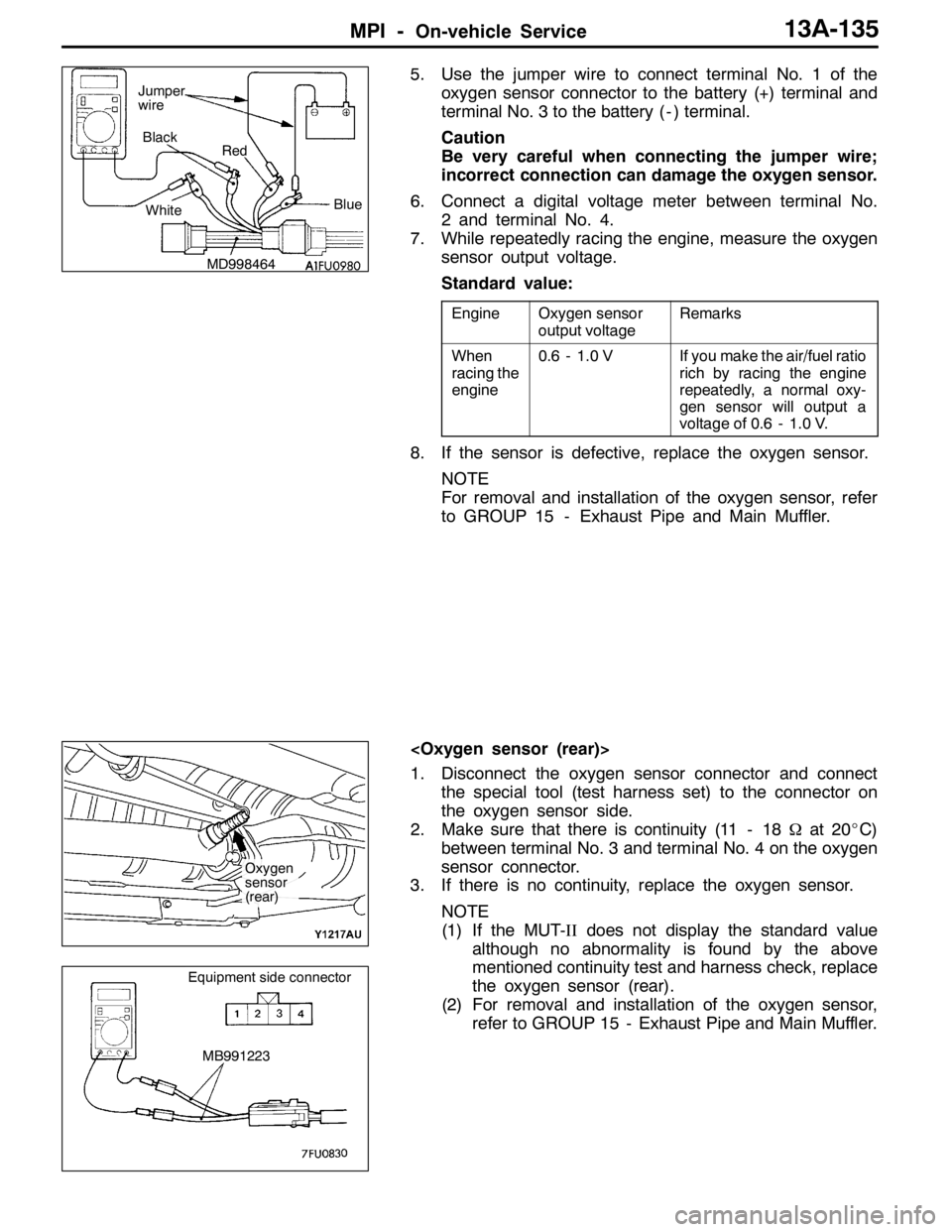
5. Use the jumper wire to connect terminal No. 1 of the
oxygen sensor connector to the battery (+) terminal and
terminal No. 3 to the battery ( - ) terminal.
Caution
Be very careful when connecting the jumper wire;
incorrect connection can damage the oxygen sensor.
6. Connect a digital voltage meter between terminal No.
2 and terminal No. 4.
7. While repeatedly racing the engine, measure the oxygen
sensor output voltage.
Standard value:
EngineOxygen sensor
output voltageRemarks
When
racing the
engine0.6 - 1.0 VIf you make the air/fuel ratio
rich by racing the engine
repeatedly, a normal oxy-
gen sensor will output a
voltage of 0.6 - 1.0 V.
8. If the sensor is defective, replace the oxygen sensor.
NOTE
For removal and installation of the oxygen sensor, refer
to GROUP 15 - Exhaust Pipe and Main Muffler.
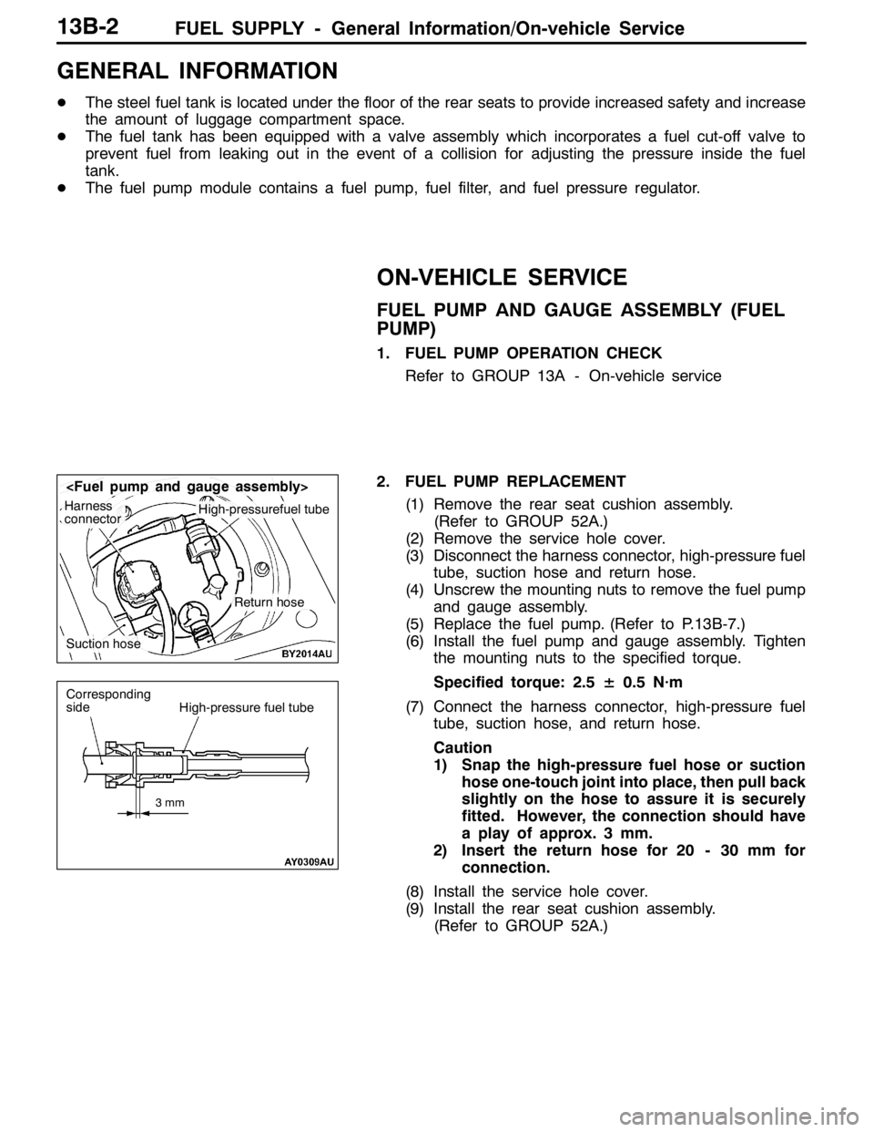
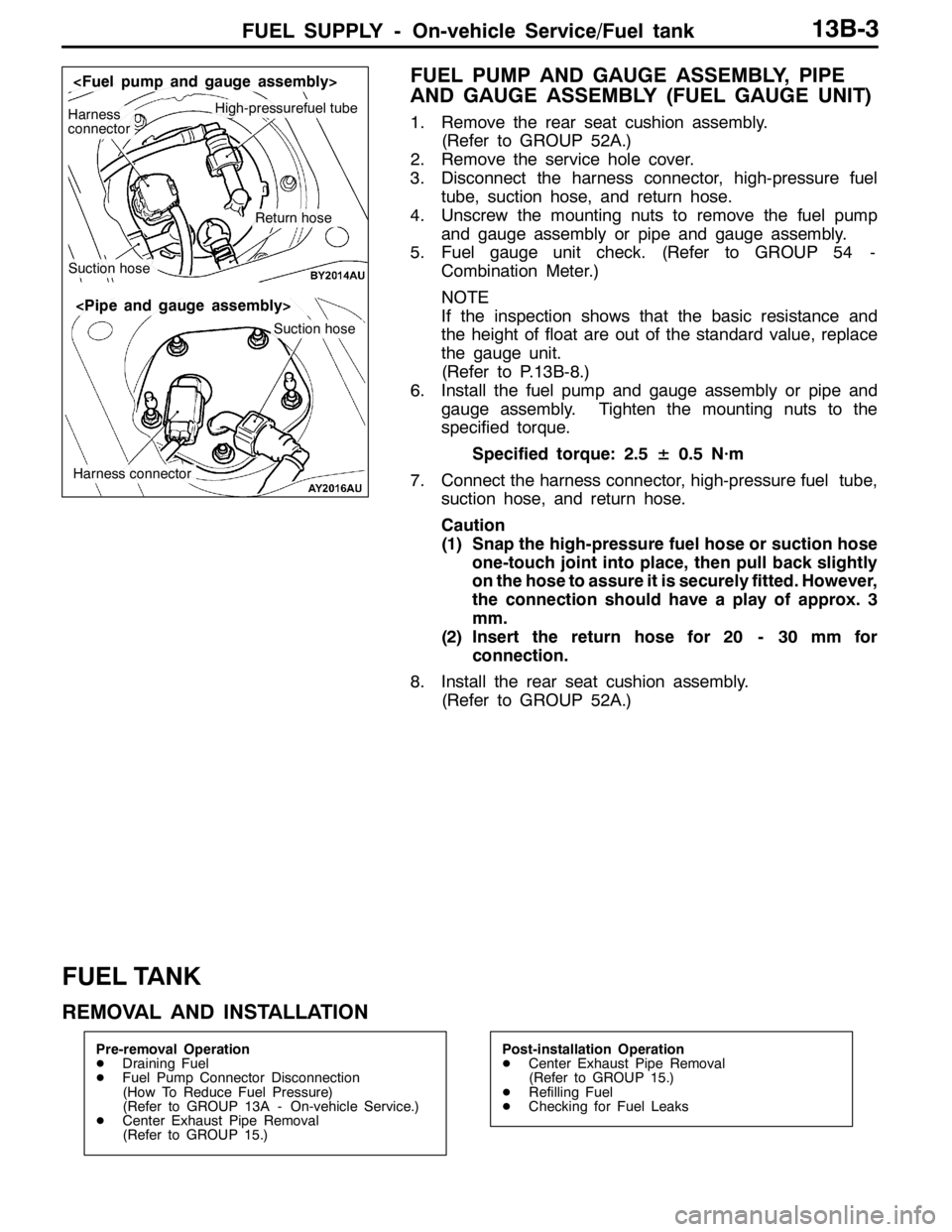
1. Disconnect the oxygen sensor connector and connect
the special tool (test harness set) to the connector on
the oxygen sensor side.
2. Make sure that there is continuity (11 - 18Ωat 20_C)
between terminal No. 3 and terminal No. 4 on the oxygen
sensor connector.
3. If there is no continuity, replace the oxygen sensor.
NOTE
(1) If the MUT-IIdoes not display the standard value
although no abnormality is found by the above
mentioned continuity test and harness check, replace
the oxygen sensor (rear).
(2) For removal and installation of the oxygen sensor,
refer to GROUP 15 - Exhaust Pipe and Main Muffler.
MD998464Blue Black
Red
White Jumper
wire
Oxygen
sensor
(rear)
MB991223
Equipment side connector
Page 677 of 1449
MPI -Throttle Body13A-145
3. After installing the Throttle position sensor, check that
the output voltage is at the standard value. If deviated
from the standard value, loosen the screw, readjust to
the standard position, and then fix. Repeat this step until
the output voltage is at the standard value.
4. Connect a circuit tester across terminal No. 1 (Throttle
position sensor power) and terminal No. 2 (Throttle
position sensor output). Check that the resistance
changes smoothly when the throttle valve is slowly moved
to the fully opened position.Throttle position
sensor output
Throttle position
sensor powerEarth
Open
Page 682 of 1449

FUEL SUPPLY - General Information/On-vehicle Service13B-2
GENERAL INFORMATION
DThe steel fuel tank is located under the floor of the rear seats to provide increased safety and increase
the amount of luggage compartment space.
DThe fuel tank has been equipped with a valve assembly which incorporates a fuel cut-off valve to
prevent fuel from leaking out in the event of a collision for adjusting the pressure inside the fuel
tank.
DThe fuel pump module contains a fuel pump, fuel filter, and fuel pressure regulator.
ON-VEHICLE SERVICE
FUEL PUMP AND GAUGE ASSEMBLY (FUEL
PUMP)
1. FUEL PUMP OPERATION CHECK
Refer to GROUP 13A - On-vehicle service
2. FUEL PUMP REPLACEMENT
(1) Remove the rear seat cushion assembly.
(Refer to GROUP 52A.)
(2) Remove the service hole cover.
(3) Disconnect the harness connector, high-pressure fuel
tube, suction hose and return hose.
(4) Unscrew the mounting nuts to remove the fuel pump
and gauge assembly.
(5) Replace the fuel pump. (Refer to P.13B-7.)
(6) Install the fuel pump and gauge assembly. Tighten
the mounting nuts to the specified torque.
Specified torque: 2.5± 0.5 N·m
(7) Connect the harness connector, high-pressure fuel
tube, suction hose, and return hose.
Caution
1) Snap the high-pressure fuel hose or suction
hose one-touch joint into place, then pull back
slightly on the hose to assure it is securely
fitted. However, the connection should have
a play of approx. 3 mm.
2) Insert the return hose for 20 - 30 mm for
connection.
(8) Install the service hole cover.
(9) Install the rear seat cushion assembly.
(Refer to GROUP 52A.)
Harness
connectorHigh-pressurefuel tube
Suction hose
Return hose
3mm
Corresponding
sideHigh-pressure fuel tube
Page 683 of 1449

FUEL SUPPLY - On-vehicle Service/Fuel tank13B-3
FUEL PUMP AND GAUGE ASSEMBLY, PIPE
AND GAUGE ASSEMBLY (FUEL GAUGE UNIT)
1. Remove the rear seat cushion assembly.
(Refer to GROUP 52A.)
2. Remove the service hole cover.
3. Disconnect the harness connector, high-pressure fuel
tube, suction hose, and return hose.
4. Unscrew the mounting nuts to remove the fuel pump
and gauge assembly or pipe and gauge assembly.
5. Fuel gauge unit check. (Refer to GROUP 54 -
Combination Meter.)
NOTE
If the inspection shows that the basic resistance and
the height of float are out of the standard value, replace
the gauge unit.
(Refer to P.13B-8.)
6. Install the fuel pump and gauge assembly or pipe and
gauge assembly. Tighten the mounting nuts to the
specified torque.
Specified torque: 2.5± 0.5 N·m
7. Connect the harness connector, high-pressure fuel tube,
suction hose, and return hose.
Caution
(1) Snap the high-pressure fuel hose or suction hose
one-touch joint into place, then pull back slightly
on the hose to assure it is securely fitted. However,
the connection should have a play of approx. 3
mm.
(2) Insert the return hose for 20 - 30 mm for
connection.
8. Install the rear seat cushion assembly.
(Refer to GROUP 52A.)
FUEL TANK
REMOVAL AND INSTALLATION
Pre-removal Operation
DDraining Fuel
DFuel Pump Connector Disconnection
(How To Reduce Fuel Pressure)
(Refer to GROUP 13A - On-vehicle Service.)
DCenter Exhaust Pipe Removal
(Refer to GROUP 15.)Post-installation Operation
DCenter Exhaust Pipe Removal
(Refer to GROUP 15.)
DRefilling Fuel
DChecking for Fuel Leaks
High-pressurefuel tubeHarness
connector
Suction hose
Return hose
Suction hose
Harness connector
Page 684 of 1449

FUEL SUPPLY - Fuel Tank13B-4
12
10
6 21
1
2
4
7 8
915 18
23 20
13 314
22
24 1119
5
16 175
2.5±0.5 N·m
2.5±0.5 N·m
26±4 N·m
22±4 N·m
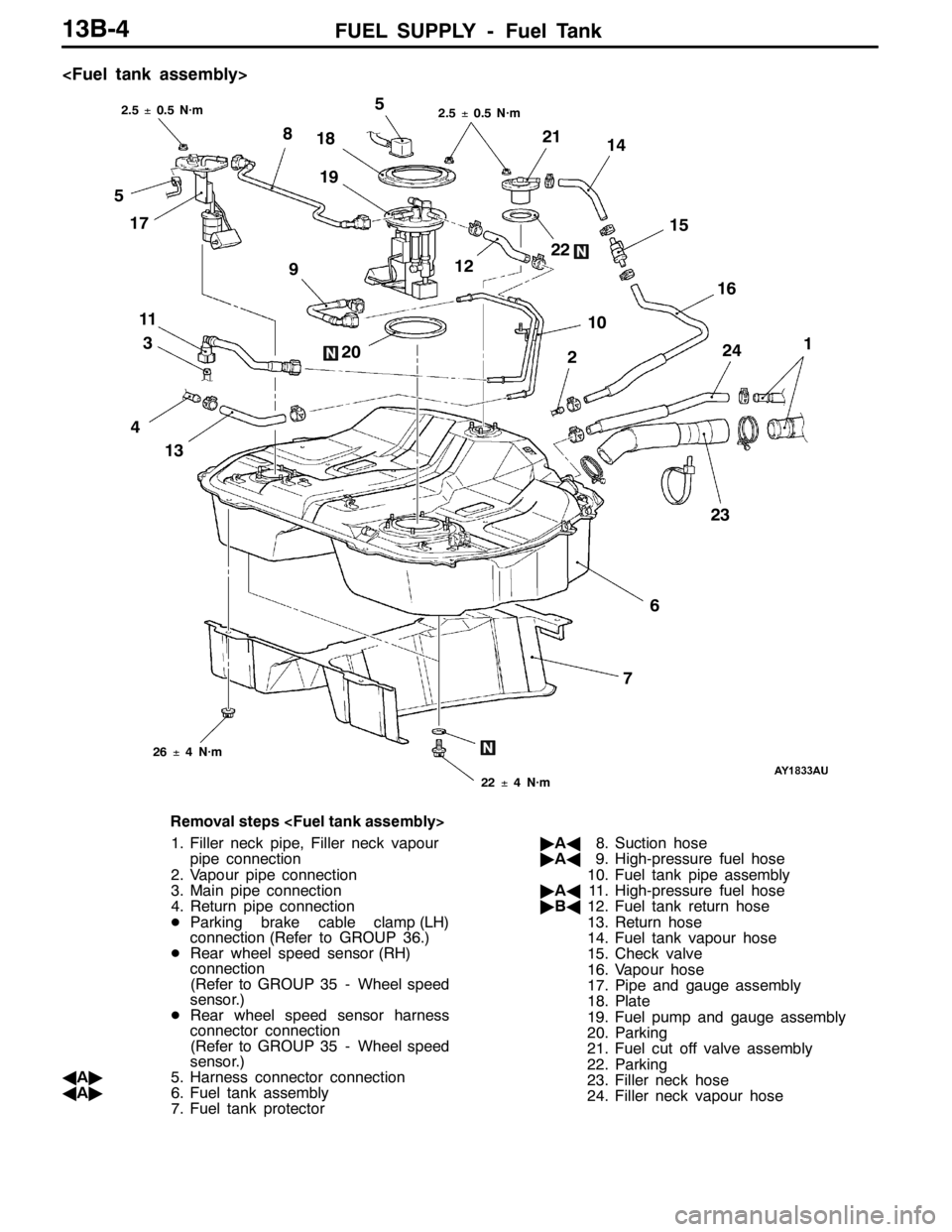
Removal steps
1. Filler neck pipe, Filler neck vapour
pipe connection
2. Vapour pipe connection
3. Main pipe connection
4. Return pipe connection
DParking brake cable clamp (LH)
connection (Refer to GROUP 36.)
DRear wheel speed sensor (RH)
connection
(Refer to GROUP 35 - Wheel speed
sensor.)
DRear wheel speed sensor harness
connector connection
(Refer to GROUP 35 - Wheel speed
sensor.)
AA"5. Harness connector connection
AA"6. Fuel tank assembly
7. Fuel tank protector"AA8. Suction hose
"AA9. High-pressure fuel hose
10. Fuel tank pipe assembly
"AA11. High-pressure fuel hose
"BA12. Fuel tank return hose
13. Return hose
14. Fuel tank vapour hose
15. Check valve
16. Vapour hose
17. Pipe and gauge assembly
18. Plate
19. Fuel pump and gauge assembly
20. Parking
21. Fuel cut off valve assembly
22. Parking
23. Filler neck hose
24. Filler neck vapour hose
Page 696 of 1449
ENGINE COOLING -On-vehicle Service14-8
RADIATOR FAN RELAY CONTINUITY CHECK
Battery voltageTerminal No.
1234
When current is not
supplied
When current is
supplied
RADIATOR FAN CONTROLLER CHECK
1. Remove the center under cover.
(Refer to GROUP 51 - Front Bumper.)
2. Insert the special tool at the back of the radiator fan
motor connector.
3. Connect the special tool to the circuit tester.
4. Disconnect the engine coolant temperature sensor
connector.
Air cleaner
Radiator fan
controller
MB991222
Circuit tester
Connector
rear view
Water outlet
fitting
Engine coolant
temperature
sensor