Page 395 of 1449
GENERAL -Major Specifications00-17
MAJOR SPECIFICATIONS
1
234
5
6 78
9
ItemsCT9A
SNDFZL/RSNGFZL/R
Vehicle
di i
Front track11,500, 1,515*1
dimensions
mmOverall width21,770mm
Front overhang3895
Wheel base42,625
Rear overhang5935
Overall length64,455
Ground clearance
(unladen)7140
Overall height (unladen)81,450
Rear track91,500, 1,515*1
Vehicle
ihtk
Kerb weight1,3201,380
weight kgMax. gross vehicle weight1,6551,695
Max. axle weight
rating-front950970
Max. axle weight
rating-rear705725
Seating capacity5
EngineModel No.4G63g
Total displacement mL1,997
Transmis-
i
Model No.W5M51
sionType5-speed manual
Fuel systemFuel supply systemMPI
NOTE
*1: Vehicles with 17 inch wheels.
Page 401 of 1449

GENERAL -Supplemental Restraint System (SRS)00-23
SRS-ECU
Terminal No.Destination of harnessCorrective action
7Instrument panel wiring harness→EarthRepair or replace each wiring
harness
8Instrument panel wiring harness→Combination meter
(SRS warning lamp)
harness
9, 10Instrument panel wiring harness→Front passenger’s air bag
module
11 , 1 2Instrument panel wiring harness→Clock spring→Driver’s air bag
module)Repair or replace the dash wiring
harness. Replace clock spring.
13Instrument panel wiring harness→Junction block (fuse No.3)Repair or replace each wiring
harness
16Instrument panel wiring harness→Junction block (fuse No.2)
harness.
20Instrument panel wiring harness→Diagnosis connector
29, 30Floor wiring harness�àDriver’s seat belt pre-tensioner
27, 28Floor wiring harness�àFront passenger’s seat belt pre-tensioner
6. Inspection of the SRS-ECU harness connector should be carried out by the following procedure.
Insert the special tool (probe, MB991222, in the harness set) into the connector from harness side
(rear side), and connect the tester to this probe. If any tool than specified is used, damage to the
harness and other components will result. Furthermore, measurement should not be carried out by
touching the probe directly against the terminals from the front of the connector. The terminals are
plated to increase their conductivity, so that if they are touched directly by the probe, the plating
may break, which will cause drops in reliability.
MB991222 SRS-ECU harness connector
SRS-ECU harness connector (rear view)
7. SRS components and seat belt with pre-tensioner should not be subjected to hart, so remove the
SRS-ECU, driver’s and front passenger’s air bag modules, clock spring, and seat belt with pre-tensioner
before drying or baking the vehicle after painting.
DSRS - ECU, air bag module, clock spring : 93�Æ
or more
DSeat belt with pre-tensioner : 90�Æ
or more
8. Whenever you finish servicing the SRS, check warning lamp operation to make sure that the system
functions properly. (Refer to P.52B-6.)
9. Make certain that the ignition switch is LOCK (OFF) position when the MUT-IIis connected or
disconnected.
10. If you have any questions about the SRS, please contact your local distributor.
NOTE
SERIOUS INJURY CAN RESULT FROM UNINTENDED AIR BAG DEPLOYMENT, SO USE ONLY
THE PROCEDURES AND EQUIPMENT SPECIFIED IN THIS MANUAL.
Page 403 of 1449
GENERAL -Support Locations for Lifting and Jacking00-25
SUPPORT POSITIONS FOR AXLE STANDS AND A SINGLE-POST LIFT OR
DOUBLE-POST LIFT
Caution
1. If rubber attachments with grooves that are too thick are used at the front support positions,
the front fender may become bent, so be sure to use rubber attachments with groove thicknesses
of 18 mm or less.
2. If attachments which are not high enough are used, they may damage areas such as the side
step. Be sure to use attachments which are high enough, or remove the side step if not using
attachments.
Bolts
RubberRubber
BoltsSide sill rear end
Side sill rear end
AttachmentAttachment
AXLE STANDS
SINGLE-POST
LIFT OR DOUBLE-
POST LIFT
Page 404 of 1449

GENERAL -Support Locations for Lifting and Jacking00-26
PLATE TYPE LIFT
To avoid damaging the side sill garnish, put a wooden block between the side sill and a lift.
NOTE
The wooden block should be 100 mm wide and 50 mm high.
SUPPORT POSITIONS AND SUPPORT METHOD
FOR AN H-BAR LIFT
Caution
When service procedures require removing the rear
suspension, fuel tank, spare tyre and rear bumper, place
additional weight on rear end of vehicle or anchor vehicle
to hoist to prevent tipping of centre of gravity changes.
When H-bar lift is used to lift up vehicles, use of metallic
attachment attached to the H-bar lift may cause damage
to the suspension arm etc. Therefore, lift up the vehicle by
the following procedure.
1. Place the vehicle on the H-bar lift (same direction).
2. Place attachments on the H-bar lift at the designated
chassis-support positions. When making the attachments,
refer to the section concerning making them.
Caution
If support is at any location other than the designated
positions, the body or suspension might be deformed
or otherwise damaged, so care should be taken to
support only at the correct (designated) positions.
3. Raise the H-bar lift to the height at which the vehicle
is slightly raised and check to be sure that the vehicle
is correctly and sufficiently secured; then raise the vehicle.
H-bar lift
H-bar lift
A
Chassis-sup-
port position
(side sill)
Attachment
H-bar liftSection A - A
Side sill
AttachmentH-bar lift
A
Page 411 of 1449
ENGINE -Special Tools11A-5
SPECIAL TOOLS
ToolNumberNameUse
MB991502MUT-IIsub
assemblyDMeasuring the drive belt tension
DChecking the ignition timing
DChecking the idle speed
DErasing diagnosis code
DMeasuring the timing belt B tension
MB991668Belt tension meter
setDMeasuring the drive belt tension
(used together with MUT-II)
DMeasuring the timing belt B tension
(used together with MUT-II)
MD998727Oil pan removerFor removing the oil pan
MD998781Flywheel stopperFor fixing the flywheel
MD998776Crankshaft
rear oil seal
installerFor pressfitting the crankshaft rear oil seal
MB990938Installer bar
MD998285Crankshaft
front oil seal
guideFor pressfitting the crankshaft front oil seal
MD998382Crankshaft
front oil seal
installer
MB991654Cylinder head bolt
wrenchFor removal and installation of cylinder head
bolts
Page 414 of 1449

ENGINE -On-vehicle Service11A-8
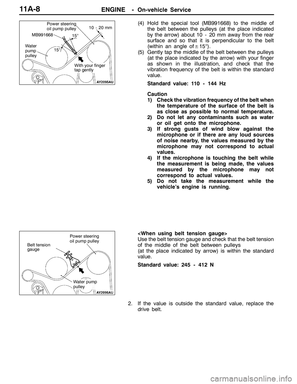
(4) Hold the special tool (MB991668) to the middle of
the belt between the pulleys (at the place indicated
by the arrow) about 10 - 20 mm away from the rear
surface and so that it is perpendicular to the belt
(within an angle of±15°).
(5) Gently tap the middle of the belt between the pulleys
(at the place indicated by the arrow) with your finger
as shown in the illustration, and check that the
vibration frequency of the belt is within the standard
value.
Standard value: 110 - 144 Hz
Caution
1) Check the vibration frequency of the belt when
the temperature of the surface of the belt is
as close as possible to normal temperature.
2) Do not let any contaminants such as water
or oil get onto the microphone.
3) If strong gusts of wind blow against the
microphone or if there are any loud sources
of noise nearby, the values measured by the
microphone may not correspond to actual
values.
4) If the microphone is touching the belt while
the measurement is being made, the values
measured by the microphone may not
correspond to actual values.
5) Do not take the measurement while the
vehicle’s engine is running.
Use the belt tension gauge and check that the belt tension
of the middle of the belt between pulleys
(at the place indicated by arrow) is within the standard
value.
Standard value: 245 - 412 N
2. If the value is outside the standard value, replace the
drive belt.Power steering
oil pump pulley
Water
pump
pulley
MB991668
10 - 20 mm
15°
15°
With your finger
tap gently
Belt tension
gauge
Power steering
oil pump pulley
Water pump
pulley
Page 424 of 1449
ENGINE -Camshaft and Camshaft Oil Seal11A-18
Apply engine oil to all
sliding parts at the time
of installation.
10±2 N·m
89±9 N·m20±1 N·m
22±4 N·m
14±1 N·m
28
29 27 26
20
14 15
16
17 19
18222321
2425
11±1 N·m
30
14. Camshaft position sensor support
cover
15. Camshaft position sensor support
cover gasket
"GA16. Camshaft position sensing cylinder
"FA17. Camshaft position sensor support
AB""EA18. Camshaft sprocket
"DA19. Camshaft oil seal
"CA20. Camshaft bearing cap front"CA21. Camshaft bearing cap rear
"CA22. Camshaft bearing cap No. 2
"CA23. Camshaft bearing cap No. 5
"CA24. Camshaft bearing cap No. 3
"CA25. Camshaft bearing cap No. 4
"BA26. Intake camshaft
"BA27. Exhaust camshaft
28. Rocker arm
"AA29. Lash adjuster
30. Oil delivery body
Page 426 of 1449

ENGINE -Camshaft and Camshaft Oil Seal11A-20
REMOVAL SERVICE POINTS
AA"RADIATOR UPPER HOSE DISCONNECTION
Indicate the mating marks on the radiator upper hose and
the hose clamp for release.
AB"CAMSHAFT SPROCKET REMOVAL
Hold the hexagon part of the camshaft with a wrench and
loosen the mounting bolt, then remove the camshaft sprocket.
INSTALLATION SERVICE POINTS
"AALASH ADJUSTER INSTALLATION
Caution
When the lash adjuster is reused, always install it after
cleaning and inspecting.
(Refer to GROUP 11B - Rocker Arms and Camshaft.)
"BAEXHAUST CAMSHAFT/INTAKE CAMSHAFT
INSTALLATION
1. Remove sealant remained on the cylinder head.
2. Apply engine oil to the cam and the journal of the camshaft.
3. Install the camshaft to the cylinder head.
Caution
Do not install wrong camshaft at the side of intake
or exhaust.
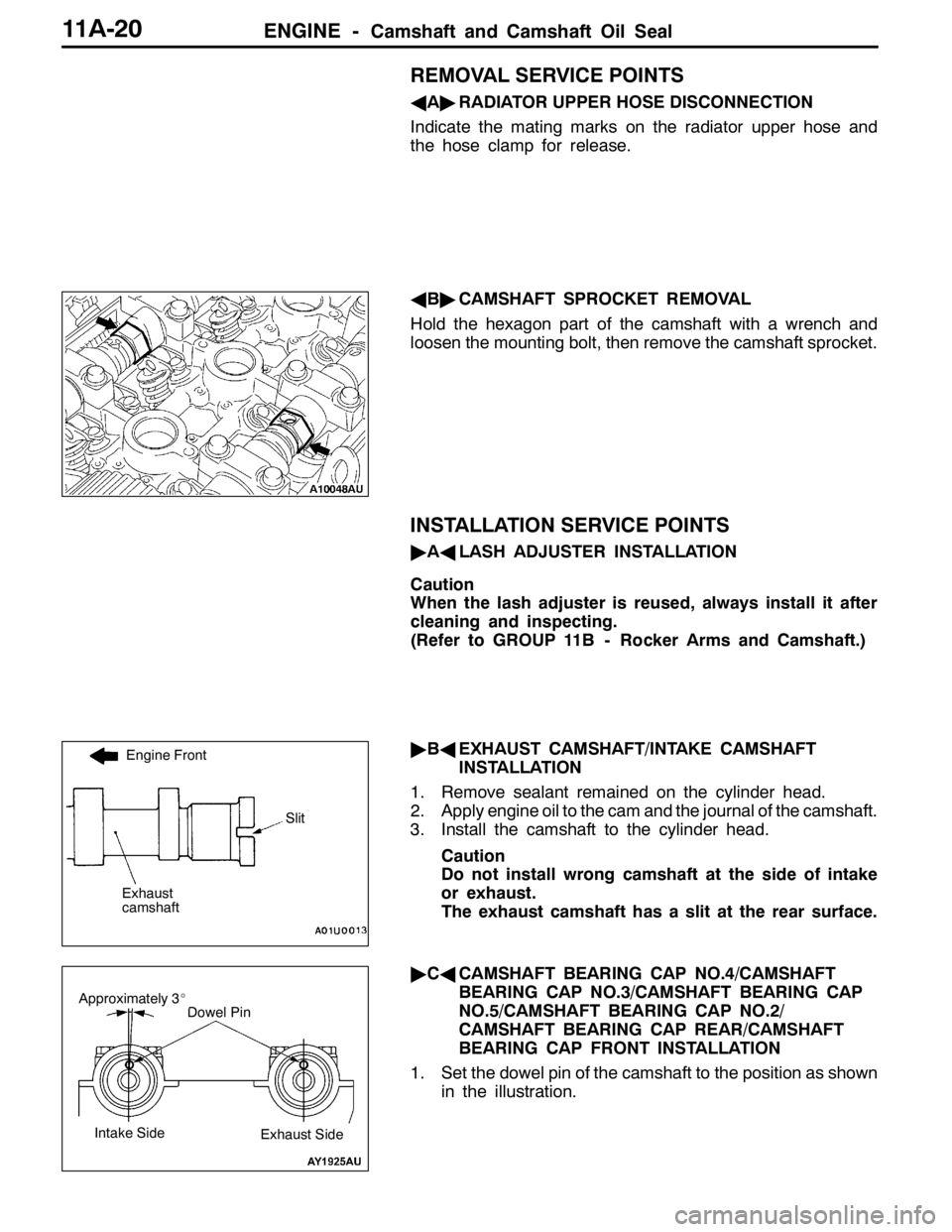
The exhaust camshaft has a slit at the rear surface.
"CACAMSHAFT BEARING CAP NO.4/CAMSHAFT
BEARING CAP NO.3/CAMSHAFT BEARING CAP
NO.5/CAMSHAFT BEARING CAP NO.2/
CAMSHAFT BEARING CAP REAR/CAMSHAFT
BEARING CAP FRONT INSTALLATION
1. Set the dowel pin of the camshaft to the position as shown
in the illustration.
Engine Front
Exhaust
camshaft
Slit
Dowel PinApproximately 3_
Intake SideExhaust Side