2007 MITSUBISHI LANCER EVOLUTION bulb
[x] Cancel search: bulbPage 183 of 1449

CIRCUIT DIAGRAMSB-85
CHARGING SYSTEM (See P.B-84.)
OPERATION
When engine is stationary
DWhen the ignition switch is turned to the ON
position, current flows the alternator L terminal
and, at the same time, the charge warning lamp
illuminates.
When engine is started and after engine has
started
DWhen the engine is started, the charge warning
lamp goes out because of the charging voltage
begin applied to the alternator L terminal.
DThe battery voltage being applied to the
alternator S terminal is monitored by the voltage
regulator. Therefore, the amount of electricity
produced by the alternator is controlled by
allowing and cutting off the current flowing to
the field coil.
DThe alternator B terminal supplies power to
each load.TROUBLESHOOTING HINTS
1. Charging indicator lamp does not illuminate
when the ignition switch is turned to ON
position, before the engine starts.
DCheck multi-purpose fuse No.(2).
DCheck the bulb.
2. Charging indicator lamp fails to switch off once
the engine starts.
DCheck voltage regulator of alternator.
3. Discharged or overcharged battery.
DCheck voltage regulator of alternator.
4. Charge warning lamp illuminates dimly.
DCheck combination meter diode (for short).
Page 541 of 1449

MPI -Troubleshooting13A-9
TROUBLESHOOTING
DIAGNOSIS TROUBLESHOOTING FLOW
Refer to GROUP 00 - How to Use Troubleshooting/Inspection
Service Point.
NOTE
If the engine-ECU is replaced, the immobilizer-ECU and
ignition key should be replaced together with it.
DIAGNOSIS FUNCTION
ENGINE WARNING LAMP (CHECK ENGINE LAMP)
If an abnormality occurs in any of the following items related
to the MPI system, the engine warning lamp will illuminate
or flash. If the lamp remains illuminated or if the lamp
illuminates while the engine is running, check the diagnosis
code output.
However, the warning lamp will illuminate as bulb check for
5 seconds whenever the ignition switch is turned to the ON
position.
Engine warning lamp inspection items
Code No.Diagnosis item
-Engine-ECU
P0100Air flow sensor system
P0105Barometric pressure sensor system
P0110Intake air temprature sensor system
P0115Engine coolant temperature sensor system
P0120Throttle position sensor system
P0130Oxygen sensor (front) system
P0135Oxygen sensor heater (front) system
P0136Oxygen sensor (rear) system
P0141Oxygen sensor heater (rear) system
P0201No.1 injector system
P0202No.2 injector system
P0203No.3 injector system
P0204No.4 injector system
P0325Detonation sensor system
P0335Crank angle sensor system
P0340Camshaft position sensor system
P0403EGR control solenoid valve system
Engine warning lamp
(check engine lamp)
Page 588 of 1449
MPI -Troubleshooting13A-56
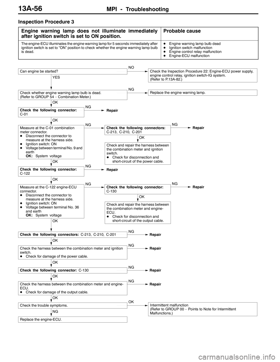
Inspection Procedure 3
Engine warning lamp does not illuminate immediately
after ignition switch is set to ON position.
Probable cause
The engine-ECU illuminates the engine warning lamp for 5 seconds immediately after
ignition switch is set to “ON” position to check whether the engine warning lamp bulb
is dead.DEngine warning lamp bulb dead
DIgnition switch malfunction
DEngine control relay malfunction
DEngine-ECU malfunction
NG
Replace the engine-ECU.
OK
Check the trouble symptoms.OKIntermittent malfunction
(Refer to GROUP 00 - Points to Note for Intermittent
Malfunctions.)
OK
Check the harness between the combination meter and engine-
ECU.
DCheck for damage of the output cable.NG
Repair
OK
Check the following connector:C-130NG
Repair
OK
Check the harness between the combination meter and ignition
switch.
DCheck for damage of the power cable.NG
Repair
OK
Check the following connectors:C-213, C-210, C-201NG
Repair
OK
Check and repair the harness between
the combination meter and engine-
ECU.
DCheck for disconnection and
short-circuit of the output cable.
OK
Measure at the C-122 engine-ECU
connector.
DDisconnect the connector to
measure at the harness side.
DIgnition switch: ON
DVoltage between terminal No. 36
and earth
OK:System voltageNGCheck the following connector:
C-130NG
Repair
OK
Check the following connector:
C-122NG
Repair
OK
Check and repair the harness between
the combination meter and ignition
switch.
DCheck for disconnection and
short-circuit of the power cable.
OK
Measure at the C-01 combination
meter connector.
DDisconnect the connector to
measure at the harness side.
DIgnition switch: ON
DVoltage between terminal No. 9 and
earth
OK:System voltageNGCheck the following connectors:
C-213, C-210, C-201NG
Repair
OK
Check the following connector:
C-01NG
Repair
YES
Check whether engine warning lamp bulb is dead.
(Refer to GROUP 54 - Combination Meter.)NGReplace the engine warning lamp.
Can engine be started?NOCheck the Inspection Procedure 22: Engine-ECU power supply,
engine control relay, ignition switch-IG system.
(Refer to P.13A-82.)
Page 631 of 1449
MPI -Troubleshooting13A-99
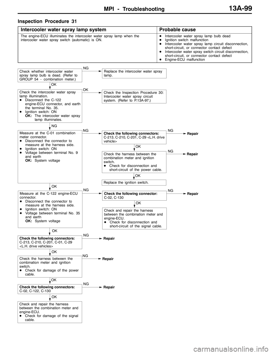
Inspection Procedure 31
Intercooler water spray lamp system
Probable cause
The engine-ECU illuminates the intercooler water spray lamp when the
intercooler water spray switch (automatic) is ON.DIntercooler water spray lamp bulb dead
DIgnition switch malfunction
DIntercooler water spray lamp circuit disconnection,
short-circuit, or connector contact defect
DIntercooler water spray switch circuit disconnection,
short-circuit, or connector contact defect
DEngine-ECU malfunction
OK
Check and repair the harness
between the combination meter and
engine-ECU.
DCheck for damage of the signal
cable.
NG
OK
Replace the intercooler water spray
lamp.Check whether intercooler water
spray lamp bulb is dead. (Refer to
GROUP 54 - combination meter.)
NGNG
Repair
OK
Check and repair the harness
between the combination meter and
engine-ECU.
DCheck for disconnection and
short-circuit of the signal cable.
Check the following connector:
C-02, C-130
OKMeasure at the C-122 engine-ECU
connector.
DDisconnect the connector to
measure at the harness side.
DIgnition switch: ON
DVoltage between terminal No. 35
and earth
OK:System voltageOK
Check the Inspection Procedure 30:
Intercooler water spray circuit
system. (Refer to P.13A-97.)Check the intercooler water spray
lamp illumination.
DDisconnect the C-122
engine-ECU connector, and earth
the terminal No. 35.
DIgnition switch: ON
OK:The intercooler water spray
lamp illuminates.
NG
NG
Measure at the C-01 combination
meter connector.
DDisconnect the connector to
measure at the harness side.
DIgnition switch: ON
DVoltage between terminal No. 9
and earth
OK:System voltage
OKNG
Repair
OK
Check the following connectors:
C-213, C-210, C-201, C-29
NG
RepairCheck the harness between the
combination meter and ignition
switch.
DCheck for damage of the power
cable.
OK
Check the harness between the
combination meter and ignition
switch.
DCheck for disconnection and
short-circuit of the power cable.Repair
Replace the ignition switch.
OK
Check the following connectors:
C-213, C-210, C-201, C-01, C-29
Repair
OK
Check the following connectors:
C-02, C-122, C-130NG
RepairNG
Page 833 of 1449
MANUAL TRANSMISSION - Troubleshooting
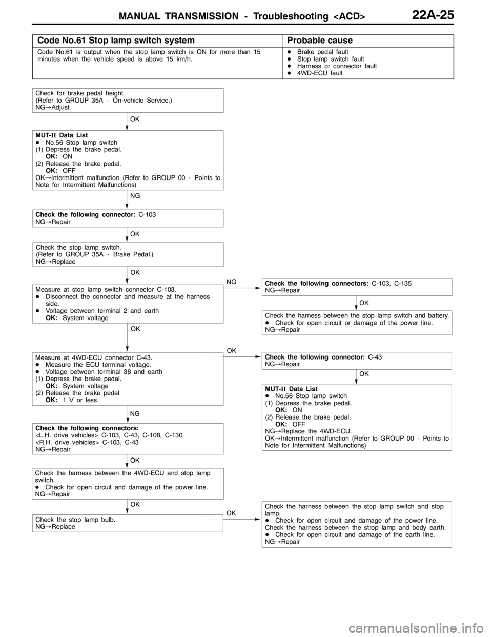
Code No.61 Stop lamp switch systemProbable cause
Code No.61 is output when the stop lamp switch is ON for more than 15
minutes when the vehicle speed is above 15 km/h.DBrake pedal fault
DStop lamp switch fault
DHarness or connector fault
D4WD-ECU fault
OK
OK
OK
NG
OK
Check for brake pedal height
(Refer to GROUP 35A – On-vehicle Service.)
NG→Adjust
NG
MUT-IIData List
DNo.56 Stop lamp switch
(1) Depress the brake pedal.
OK:ON
(2) Release the brake pedal.
OK:OFF
OK→Intermittent malfunction (Refer to GROUP 00 - Points to
Note for Intermittent Malfunctions)
OK
Check the following connector:C-103
NG→Repair
Check the stop lamp switch.
(Refer to GROUP 35A - Brake Pedal.)
NG→Replace
NG
OK
Check the following connectors:C-103, C-135
NG→Repair
Check the harness between the stop lamp switch and battery.
DCheck for open circuit or damage of the power line.
NG→Repair
OK
Measure at stop lamp switch connector C-103.
DDisconnect the connector and measure at the harness
side.
DVoltage between terminal 2 and earth
OK:System voltage
Measure at 4WD-ECU connector C-43.
DMeasure the ECU terminal voltage.
DVoltage between terminal 38 and earth
(1) Depress the brake pedal.
OK:System voltage
(2) Release the brake pedal
OK:1 V or less
OK
Check the following connectors:
NG→Repair
OKCheck the harness between the stop lamp switch and stop
lamp.
DCheck for open circuit and damage of the power line.
Check the harness between the strop lamp and body earth.
DCheck for open circuit and damage of the earth line.
NG→Repair
Check the harness between the 4WD-ECU and stop lamp
switch.
DCheck for open circuit and damage of the power line.
NG→Repair
Check the following connector:C-43
NG→Repair
MUT-IIData List
DNo.56 Stop lamp switch
(1) Depress the brake pedal.
OK:ON
(2) Release the brake pedal.
OK:OFF
NG→Replace the 4WD-ECU.
OK→Intermittent malfunction (Refer to GROUP 00 - Points to
Note for Intermittent Malfunctions)
OK
Check the stop lamp bulb.
NG→Replace
Page 835 of 1449
MANUAL TRANSMISSION - Troubleshooting
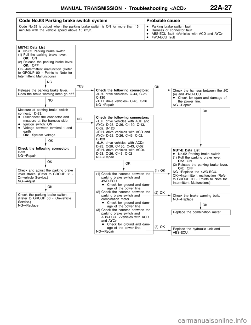
Code No.63 Parking brake switch systemProbable cause
Code No.63 is output when the parking brake switch is ON for more than 15
minutes with the vehicle speed above 15 km/h.DParking brake switch fault
DHarness or connector fault
DABS-ECU fault
D4WD-ECU fault
OK
NG
YES
NG
(3) OK(1) OKReplace the hydraulic unit and
ABS-ECU.
MUT-IIData List
DNo.62 Parking brake switch
(1) Pull the parking brake lever.
OK:ON
(2) Release the parking brake lever.
OK:OFF
OK→Intermittent malfunction (Refer
to GROUP 00 - Points to Note for
Intermittent Malfunctions)
Measure at parking brake switch
connector D-23.
DDisconnect the connector and
measure at the harness side.
DIgnition switch: ON
DVoltage between terminal 1 and
earth
OK:System voltage
Release the parking brake lever.
Does the brake warning lamp go off?
OK
Check the following connector:
D-23
NG→Repair
OK
Replace the combination meter
OK
Check the brake warning bulb.
NG→ReplaceCheck the parking brake switch.
(Refer to GROUP 36 - On-vehicle
Service.)
NG→Replace
OK
Check and adjust the parking brake
lever stroke. (Refer to GROUP 36 -
On-vehicle Service.)
NG→Adjust
MUT-IIData List
DNo.62 Parking brake switch
(1) Pull the parking brake lever.
OK:ON
(2) Release the parking brake lever.
OK:OFF
NG→Replace the 4WD-ECU.
OK→Intermittent malfunction (Refer
to GROUP 00 - Points to Note for
Intermittent Malfunctions) NOOK
Check the following connectors:
C-130
NG→Repair
Check the following connectors:
C-02, B-123
B-123
D-23, C-26, C-130, C-43, C-02
D-23, C-26, C-43, C-02
NG→Repair
(2) OK
(1) Check the harness between the
parking brake switch and
4WD-ECU.
DCheck for ground and dam-
age of the power line.
(2) Check the harness between the
parking brake switch and
combination meter.
DCheck for ground and dam-
age of the power line.
(3) Check the harness between the
parking brake switch and
ABS-ECU.
DCheck for ground and dam-
age of the power line.
NG→Repair
OK
Check the harness between the J/C
(4) and 4WD-ECU.
DCheck for open and damage of
the power line.
NG→Repair
Page 1088 of 1449
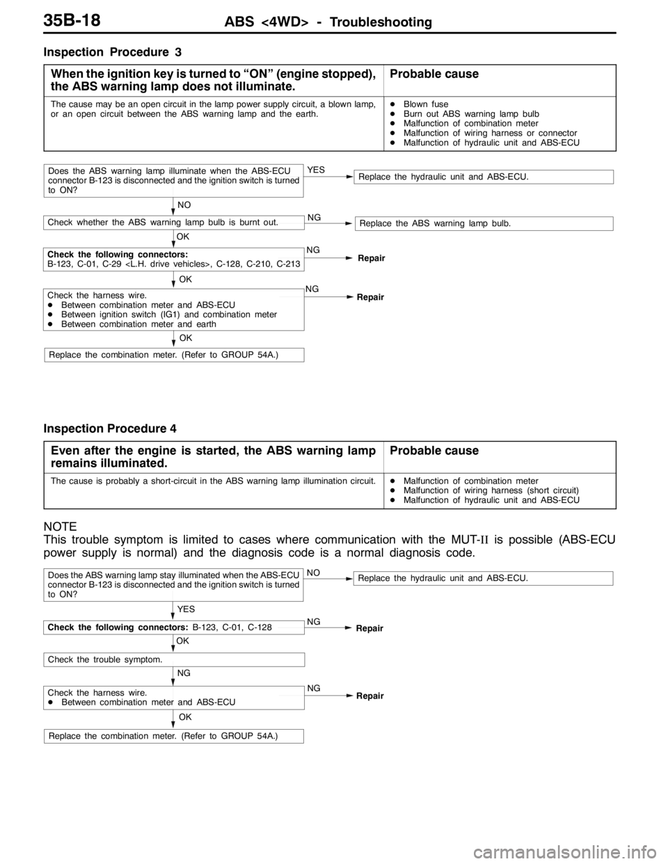
ABS <4WD> -Troubleshooting35B-18
Inspection Procedure 3
When the ignition key is turned to “ON” (engine stopped),
the ABS warning lamp does not illuminate.
Probable cause
The cause may be an open circuit in the lamp power supply circuit, a blown lamp,
or an open circuit between the ABS warning lamp and the earth.DBlown fuse
DBurn out ABS warning lamp bulb
DMalfunction of combination meter
DMalfunction of wiring harness or connector
DMalfunction of hydraulic unit and ABS-ECU
NO
NG
Replace the ABS warning lamp bulb.
Check the harness wire.
DBetween combination meter and ABS-ECU
DBetween ignition switch (IG1) and combination meter
DBetween combination meter and earth
Replace the hydraulic unit and ABS-ECU.
OKNG
OK
Check the following connectors:
B-123, C-01, C-29
OK
Check whether the ABS warning lamp bulb is burnt out.
Does the ABS warning lamp illuminate when the ABS-ECU
connector B-123 is disconnected and the ignition switch is turned
to ON?YES
Repair
Replace the combination meter. (Refer to GROUP 54A.)NG
Repair
Inspection Procedure 4
Even after the engine is started, the ABS warning lamp
remains illuminated.
Probable cause
The cause is probably a short-circuit in the ABS warning lamp illumination circuit.DMalfunction of combination meter
DMalfunction of wiring harness (short circuit)
DMalfunction of hydraulic unit and ABS-ECU
NOTE
This trouble symptom is limited to cases where communication with the MUT-IIis possible (ABS-ECU
power supply is normal) and the diagnosis code is a normal diagnosis code.
YES
NG
Check the harness wire.
DBetween combination meter and ABS-ECU
Replace the hydraulic unit and ABS-ECU.
OK
NG
OK
Check the trouble symptom.
Does the ABS warning lamp stay illuminated when the ABS-ECU
connector B-123 is disconnected and the ignition switch is turned
to ON?NO
Repair
Replace the combination meter. (Refer to GROUP 54A.)NG
Repair
Check the following connectors:B-123, C-01, C-128
Page 1277 of 1449
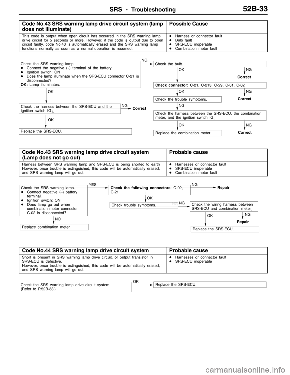
SRS -Troubleshooting52B-33
Code No.43 SRS warning lamp drive circuit system (lamp
does not illuminate)Possible Cause
This code is output when open circuit has occurred in the SRS warning lamp
drive circuit for 5 seconds or more. However, if the code is output due to open
circuit faulty, code No.43 is automatically erased and the SRS warning lamp
functions normally as soon as a normal operation is resumed.DHarness or connector fault
DBulb fault
DSRS-ECU inoperable
DCombination meter fault
NGNG
NGOK
NG
NGOK
Check the trouble symptoms.
NG
Correct
Check the harness between the SRS-ECU, the combination
meter, and the ignition switch IG1.
OK
Replace the SRS-ECU.Correct
Correct
OK
Check connector:C-21, C-213, C-29, C-01, C-02
Check the SRS warning lamp.
DConnect the negative ( - ) terminal of the battery
DIgnition switch: ON
DDoes the lamp illuminate when the SRS-ECU connector C-21 is
disconnected?
OK:Lamp illuminates.Check the bulb.
Replace the combination meter. OK
CorrectCheck the harness between the SRS-ECU and the
ignition switch IG
1.
Code No.43 SRS warning lamp drive circuit system
(Lamp does not go out)Probable cause
Harness between SRS warning lamp and SRS-ECU is being shorted to earth
However, once trouble is extinguished, this code will be automatically erased,
and SRS warning lamp will go out.DHarnesses or connector fault
DSRS-ECU inoperable
DCombination meter fault
NO
OKNG
NG
NG
Replace combination meter.
Check the SRS warning lamp.
DConnect negative (–) battery
terminal.
DIgnition switch: ON
DDoes lamp go out when
combination meter connector
C-02 is disconnected?YESCheck the following connectors:C-02,
C-21
Check trouble symptoms.
OK
Replace the SRS-ECU.
Check the wiring harness between
SRS-ECU and combination meter
.
Repair
Repair NG
Code No.44 SRS warning lamp drive circuit systemProbable cause
Short is present in SRS warning lamp drive circuit, or output transistor in
SRS-ECU is defective.
However, once trouble is extinguished, this code will be automatically erased,
and SRS warning lamp will go out.DHarnesses or connector fault
DSRS-ECU inoperable
Check the SRS warning lamp drive circuit system.
(Refer to P.52B-33.)OKReplace the SRS-ECU.