2007 MITSUBISHI LANCER EVOLUTION bulb
[x] Cancel search: bulbPage 1322 of 1449

54A-2
CHASSIS
ELECTRICAL
CONTENTS
BATTERY 4..............................
SERVICE SPECIFICATION 4....................
ON-VEHICLE SERVICE 4......................
Fluid Level and Specific Gravity Check 4........
Charging 4.................................
Battery Testing Procedure 5...................
IGNITION SWITCH AND IMMOBILIZER
SYSTEM 6...............................
SPECIAL TOOLS 6............................
TROUBLESHOOTING 6........................
IMMOBILIZER-ECU CHECK 10.................
IGNITION SWITCH 11..........................
COMBINATION METER 14................
SERVICE SPECIFICATIONS 14.................
SEALANT 14..................................
SPECIAL TOOLS 15...........................
TROUBLESHOOTING 15.......................
ON-VEHICLE SERVICE 19.....................Speedometer Check 19......................
Tachometer Check 20........................
Fuel Gauge Unit Check 20....................
Engine Coolant Temperature Gauge
Unit Check 21...............................
COMBINATION METER 22.....................
HEADLAMP ASSEMBLY 24...............
SERVICE SPECIFICATIONS 24.................
TROUBLESHOOTING 24.......................
ON-VEHICLE SERVICE 24.....................
Headlamp Aiming 24.........................
Headlamp Intensity Measurement 28...........
Headlamp Bulb(low beam)Replacement28 ....
Headlamp Bulb(high beam)Replacement29 ...
Position Lamp Bulb Replacement29 ...........
Front Turn Signal Lamp Bulb Replacement29 ...
Headlamp Auto Cut Adjustment Procedure29 ...
HeadlampAuto Cut Function Check 29.........
HEADLAMP ASSEMBLY 30....................
CONTINUED ON NEXT PAGE
Page 1323 of 1449

54A-3
SIDE TURN-SIGNAL LAMP 31............
SPECIAL TOOL 31............................
SIDE TURN-SIGNAL LAMP 31..................
ROOM LAMP 31.........................
TROUBLESHOOTING 31.......................
REAR COMBINATION LAMP 32...........
SPECIAL TOOL 32............................
TROUBLESHOOTING 32.......................
REAR COMBINATION LAMP 32................
HIGH-MOUNTED STOP LAMP 34.........
ON-VEHICLE SERVICE 34......................
High-mounted Stop Lamp Bulb Replacement 34.
HIGH-MOUNTED STOP LAMP 34................
LICENCE PLATE LAMP 35...............
ON-VEHICLE SERVICE 35.....................
License Plate Lamp Replacement 35...........
LICENCE PLATE LAMP 35.....................
HAZARD WARNING LAMP SWITCH 36....
SPECIAL TOOL 36............................
HAZARD WARNING LAMP SWITCH 36.........
HORN 37................................
CIGARETTE LIGHTER 37.................
COLUMN SWITCH 38....................
SPECIAL TOOL 38............................
COLUMN SWITCH 38..........................
CLOCK 40...............................
SPECIAL TOOL 40............................
CLOCK 40....................................
POLE ANTENNA 41......................
ROOF ANTENNA 42......................
DEFOGGER 42...........................
TROUBLESHOOTING 42......................
ON-VEHICLE SERVICE 43.....................
Printed Heater Check 43......................
Defogger Relay Continuity Check 43...........
DEFOGGER SWITCH 43.......................
Page 1343 of 1449
CHASSIS ELECTRICAL -Combination Meter54A-23
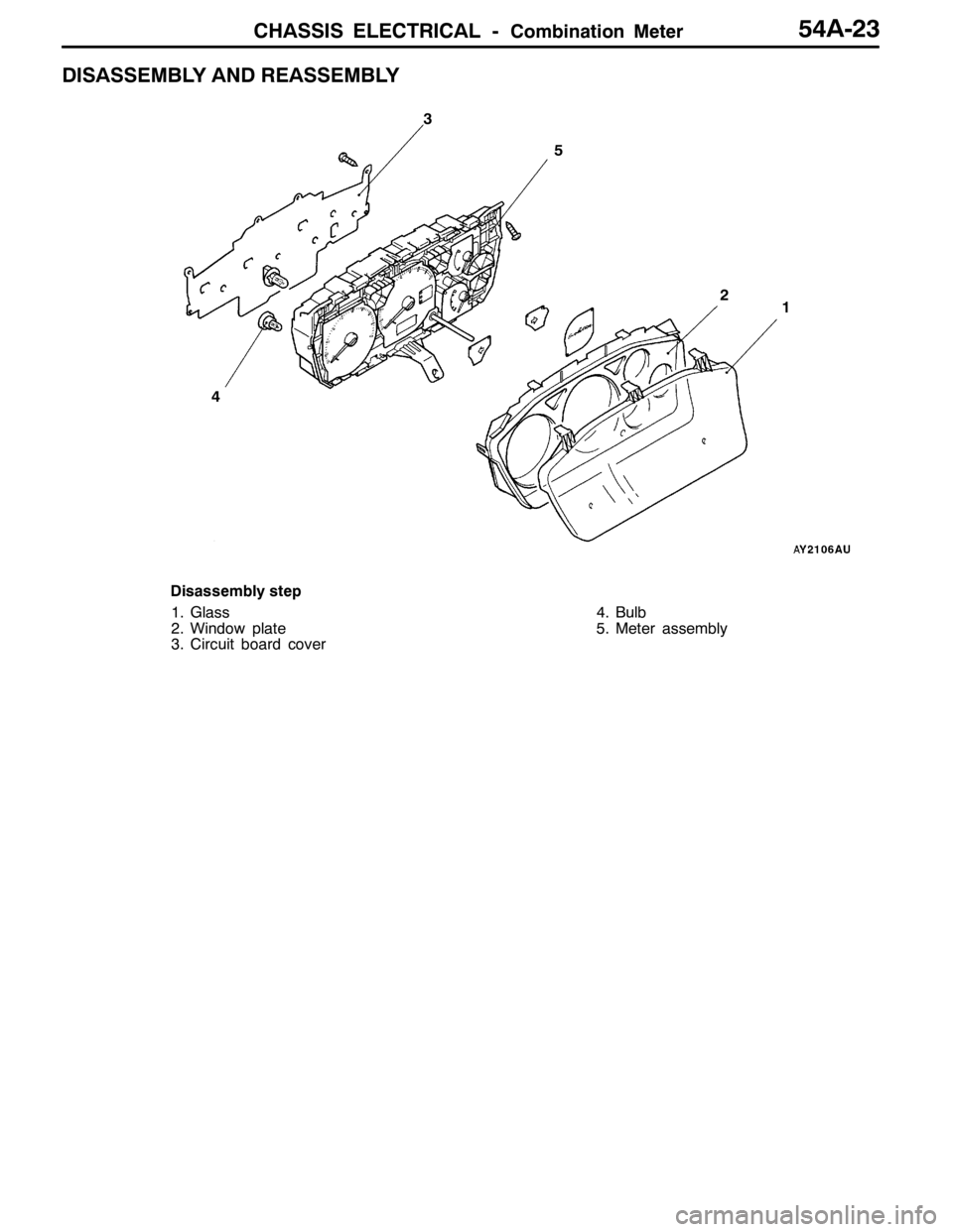
DISASSEMBLY AND REASSEMBLY
12
4
5
3
Disassembly step
1. Glass
2. Window plate
3. Circuit board cover4. Bulb
5. Meter assembly
Page 1344 of 1449

CHASSIS ELECTRICAL -Headlamp Assembly54A-24
HEADLAMP ASSEMBLY
SERVICE SPECIFICATIONS
ItemStandard valueLimit
Headlamp aimingLow beamVertical
direction120mm (0.69_) below hor-
izontal line (H)±0.29_
Horizontal
directionPosition at which the
startup point of 15_is
crossed with vertical line
(V)±0.5_
High beamVertical
directionThe center of high intensi-
ty zone is on the point of
intersection of line (H) and
line (V).- 0.5_of the point of
intersection of line (H)
Horizontal
directionThe center of high intensi-
ty zone is on the point of
intersection of line (V).±0.5_of the center of
line (V)
Measurement of headlamp illuminous intensity
(at high beam)–30,000 cd or more per
one headlamp
NOTES ON HEADLAMP ASSEMBLY:
Plastic outer lens are equipped with headlamp assembly. For handling, care should be taken for
the following items:
DHeadlamps should not be illuminated for more than 3 minutes with scratch preventive protectors,
etc. covered on them.
DMasking such as taping should not be attached on outer lens.
DOuter lens surface should not be rubbed with a sharp-edged tool, etc.
DSpecified wax remover should be used for insistently washing.
DAuthorized Mitsubishi Genuine bulbs should be used.
TROUBLESHOOTING
Headlamps are controlled smart wiring system (SWS). For troubleshooting, refer to GROUP 54B.
NOTE
When ETACS-ECU is defective, headlamps can be illuminated only in a low beam mode as fail-safe
function.
ON-VEHICLE SERVICE
HEADLAMP AIMING
PRE-AIMING INSTRUCTION
1. Inspect for badly rusted or faulty headlamp assemblies.
2. These conditions must be corrected before a satisfactory
adjustment can be made.
3. Inspect tyres inflation, and adjust if necessary.
Page 1345 of 1449
CHASSIS ELECTRICAL -Headlamp Assembly54A-25
4. If the fuel tank is not full, place a weight in luggage room
of vehicle to simulate weight of a full tank 0.8 kg per litre.
5. There should be no other load in the vehicle other than
driver or substituted weight of approximately 75 kg placed
in driver’s position.
6. Thoroughly clean headlamp lenses.
7. Place the vehicle on a level floor, perpendicular to a flat
screen 10m away from the bulb center - marks on the
headlamp lens.
8. Rock vehicle sideways to allow vehicle to assume its
normal position.
9. Bounce the front suspension through three (3) oscillations
by applying the body weight to hood or bumper.
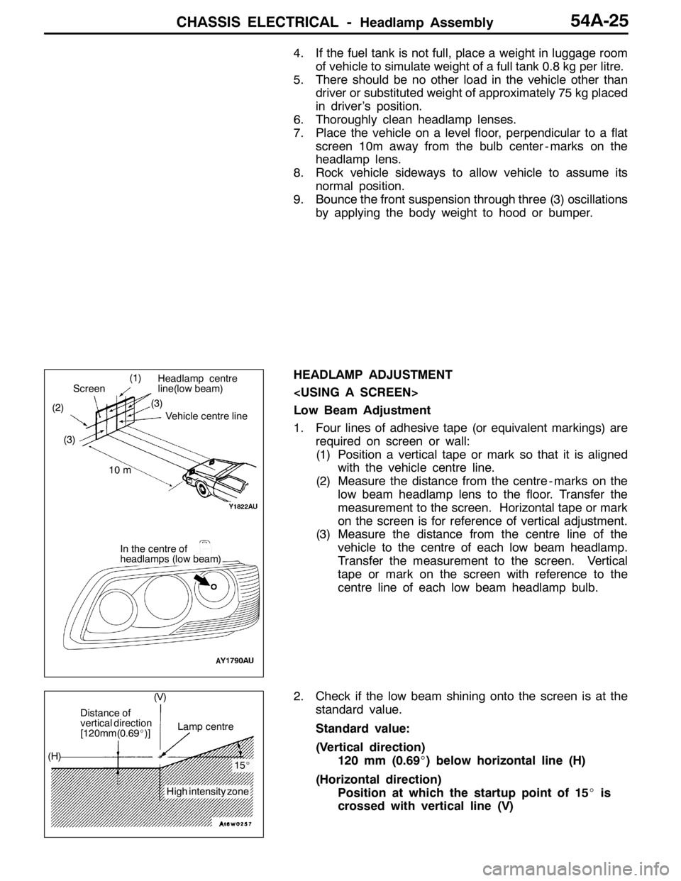
HEADLAMP ADJUSTMENT
Low Beam Adjustment
1. Four lines of adhesive tape (or equivalent markings) are
required on screen or wall:
(1) Position a vertical tape or mark so that it is aligned
with the vehicle centre line.
(2) Measure the distance from the centre - marks on the
low beam headlamp lens to the floor. Transfer the
measurement to the screen. Horizontal tape or mark
on the screen is for reference of vertical adjustment.
(3) Measure the distance from the centre line of the
vehicle to the centre of each low beam headlamp.
Transfer the measurement to the screen. Vertical
tape or mark on the screen with reference to the
centre line of each low beam headlamp bulb.
2. Check if the low beam shining onto the screen is at the
standard value.
Standard value:
(Vertical direction)
120 mm (0.69_) below horizontal line (H)
(Horizontal direction)
Position at which the startup point of 15_is
crossed with vertical line (V)
(1)
(2)(3)
Headlamp centre
line(low beam)
Vehicle centre line
Screen
10 m
In the centre of
headlamps (low beam) (3)
Distance of
vertical direction
[120mm(0.69_)]Lamp centre
15_
High intensity zone (H)(V)
Page 1346 of 1449
CHASSIS ELECTRICAL -Headlamp Assembly54A-26
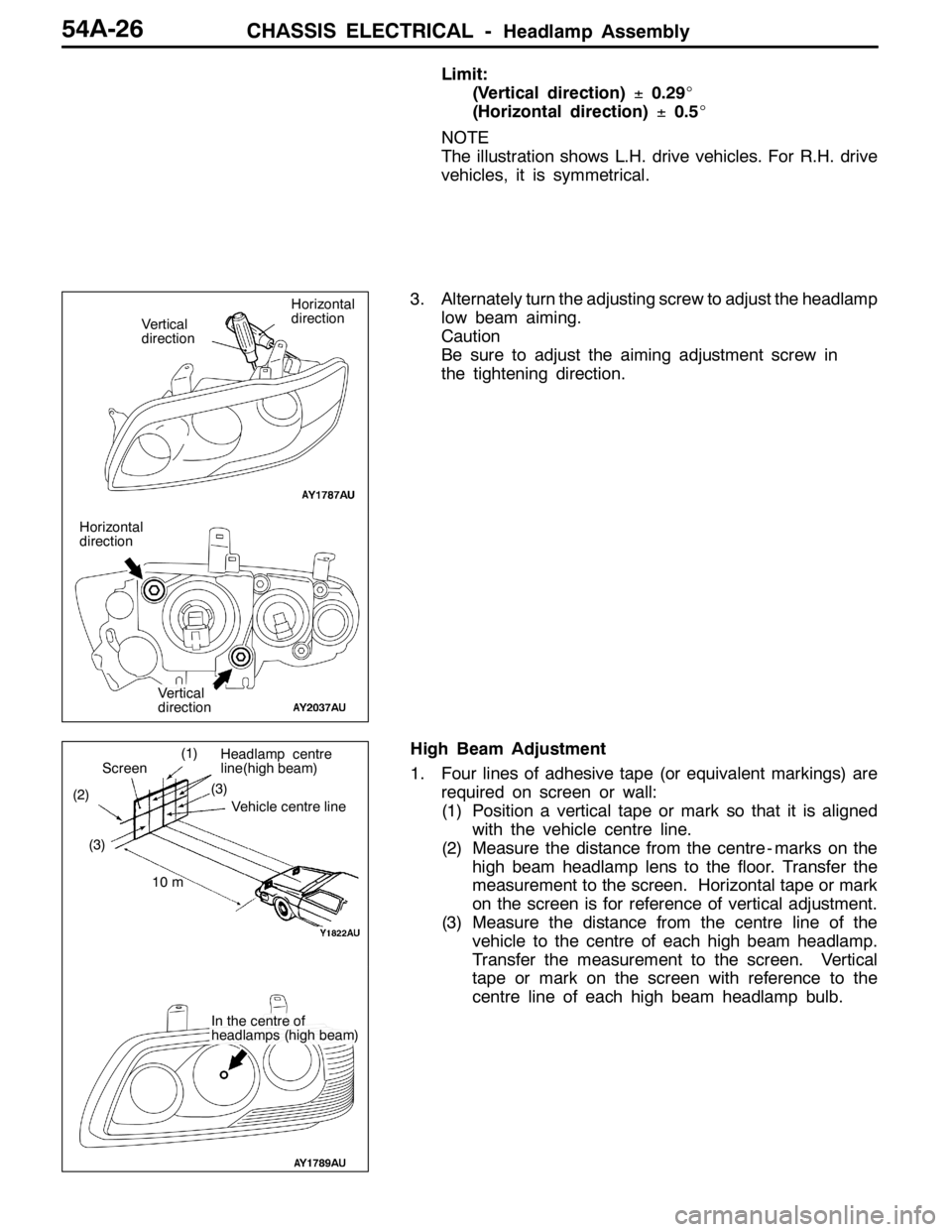
Limit:
(Vertical direction)±0.29_
(Horizontal direction)±0.5_
NOTE
The illustration shows L.H. drive vehicles. For R.H. drive
vehicles, it is symmetrical.
3. Alternately turn the adjusting screw to adjust the headlamp
low beam aiming.
Caution
Be sure to adjust the aiming adjustment screw in
the tightening direction.
High Beam Adjustment
1. Four lines of adhesive tape (or equivalent markings) are
required on screen or wall:
(1) Position a vertical tape or mark so that it is aligned
with the vehicle centre line.
(2) Measure the distance from the centre - marks on the
high beam headlamp lens to the floor. Transfer the
measurement to the screen. Horizontal tape or mark
on the screen is for reference of vertical adjustment.
(3) Measure the distance from the centre line of the
vehicle to the centre of each high beam headlamp.
Transfer the measurement to the screen. Vertical
tape or mark on the screen with reference to the
centre line of each high beam headlamp bulb.
Horizontal
direction
Vertical
direction
Horizontal
direction
Vertical
direction
(1)
(2)(3)Vehicle centre line
Screen
10 m
In the centre of
headlamps (high beam)
Headlamp centre
line(high beam)
(3)
Page 1348 of 1449
CHASSIS ELECTRICAL -Headlamp Assembly54A-28
HEADLAMP INTENSITY MEASUREMENT
1. Using a photometer, and following its manufacture’s
instruction manual.
2. Maintain an engine speed of 2,000 r/min., with the battery
in the charging condition
3. Set the headlamps to high beam
4. Measure the headlamp centre intensity (a point of H line
and V line) and check to be sure that the limit value
is satisfied.
Limit:
High beam 30,000 cd or more per one headlamp
NOTE
1. There may be special local regulations pertaining to
headlamp intensity, be sure to make any adjustments
necessary to satisfy such regulations.
2. If an illuminometer is used to make the measurements,
convert its values to photometer values by using the
following formula.
I=Er
2Where:
I=intensity (cd)
E=illumination (lux)
r=distance (m) from headlamps to illuminometer
Caution
1. On the headlamp not yet adjusted, perform aiming
with connector removed and the lamps switched off,
if applicable. In addition, care should be taken to
prevent a change of optical axis when connector is
reconnected.
2. Plastic outer lens are equipped with headlamps. When
lens surface is covered with materials for not
penetrating light, headlamp operation time should be
within 3 minutes. In addition, masking such as taping
should not be performed.
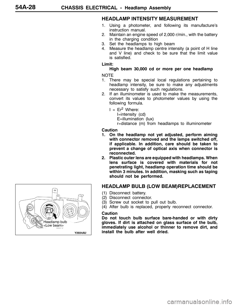
HEADLAMP BULB (LOW BEAM)REPLACEMENT
(1) Disconnect battery.
(2) Disconnect connector.
(3) Screw out socket to pull out bulb.
(4) After bulb is replaced, properly reconnect connector.
Caution
Do not touch bulb surface bare-handed or with dirty
gloves. If dirt is attached on glass surface of the bulb,
immediately use alcohol or thinner to remove dirt, and
install the bulb after well dried.
Headlamp bulb
Page 1349 of 1449
CHASSIS ELECTRICAL -Headlamp AssemblyCHASSIS ELECTRICAL -Headlamp AssemblyCHASSIS ELECTRICAL -Headlamp Assembly54A-29
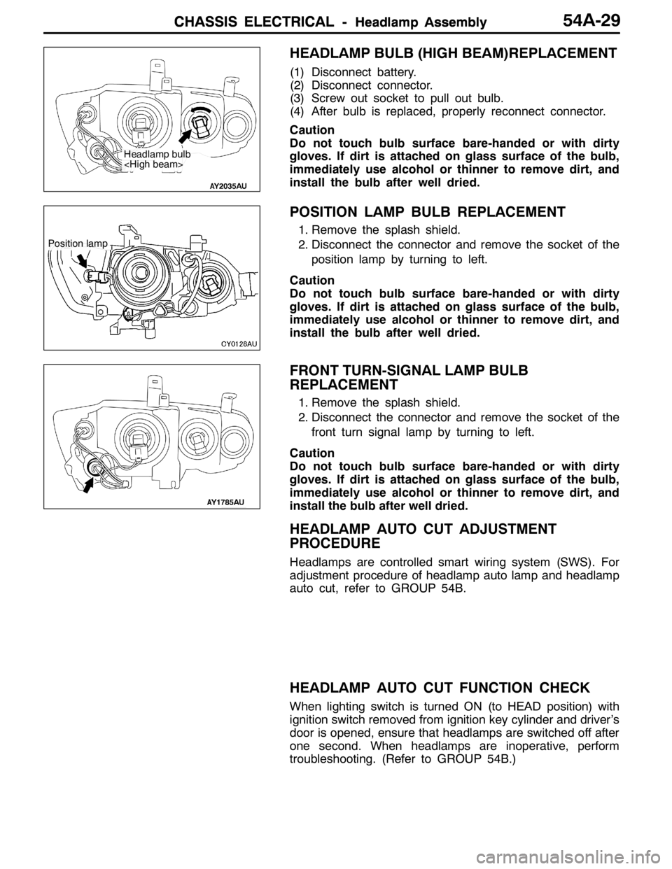
HEADLAMP BULB (HIGH BEAM)REPLACEMENT
(1) Disconnect battery.
(2) Disconnect connector.
(3) Screw out socket to pull out bulb.
(4) After bulb is replaced, properly reconnect connector.
Caution
Do not touch bulb surface bare-handed or with dirty
gloves. If dirt is attached on glass surface of the bulb,
immediately use alcohol or thinner to remove dirt, and
install the bulb after well dried.
POSITION LAMP BULB REPLACEMENT
1. Remove the splash shield.
2. Disconnect the connector and remove the socket of the
position lamp by turning to left.
Caution
Do not touch bulb surface bare-handed or with dirty
gloves. If dirt is attached on glass surface of the bulb,
immediately use alcohol or thinner to remove dirt, and
install the bulb after well dried.
FRONT TURN-SIGNAL LAMP BULB
REPLACEMENT
1. Remove the splash shield.
2. Disconnect the connector and remove the socket of the
front turn signal lamp by turning to left.
Caution
Do not touch bulb surface bare-handed or with dirty
gloves. If dirt is attached on glass surface of the bulb,
immediately use alcohol or thinner to remove dirt, and
install the bulb after well dried.
HEADLAMP AUTO CUT ADJUSTMENT
PROCEDURE
Headlamps are controlled smart wiring system (SWS). For
adjustment procedure of headlamp auto lamp and headlamp
auto cut, refer to GROUP 54B.
HEADLAMP AUTO CUT FUNCTION CHECK
When lighting switch is turned ON (to HEAD position) with
ignition switch removed from ignition key cylinder and driver’s
door is opened, ensure that headlamps are switched off after
one second. When headlamps are inoperative, perform
troubleshooting. (Refer to GROUP 54B.)
Headlamp bulb
Position lamp