2007 INFINITI QX56 service indicator
[x] Cancel search: service indicatorPage 1783 of 3061
DRIVE BELTSEM-13
< SERVICE INFORMATION >
C
DE
F
G H
I
J
K L
M A
EM
NP
O
DRIVE BELTS
Checking Drive BeltsINFOID:0000000003531521
WARNING:
Be sure to perform when the engine is stopped.
1. Remove air duct and resonator assembly when inspecting drive belt.
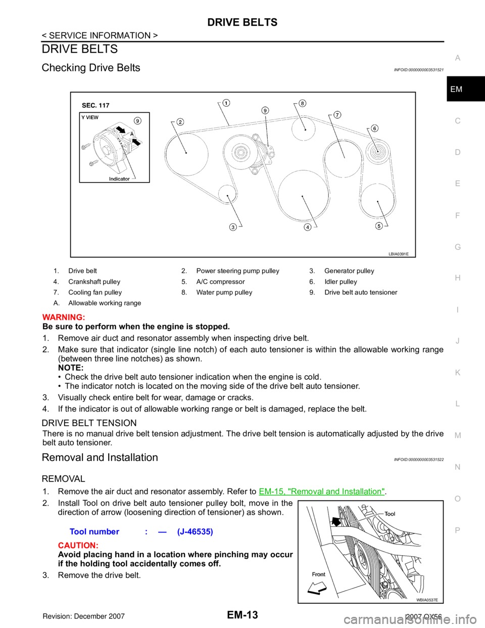
2. Make sure that indicator (single line notch) of eac
h auto tensioner is within the allowable working range
(between three line notches) as shown.
NOTE:
• Check the drive belt auto tensioner indication when the engine is cold.
• The indicator notch is located on the moving side of the drive belt auto tensioner.
3. Visually check entire belt for wear, damage or cracks.
4. If the indicator is out of allowable work ing range or belt is damaged, replace the belt.
DRIVE BELT TENSION
There is no manual drive belt tension adjustment. The driv e belt tension is automatically adjusted by the drive
belt auto tensioner.
Removal and InstallationINFOID:0000000003531522
REMOVAL
1. Remove the air duct and resonator assembly. Refer to EM-15, "Removal and Installation".
2. Install Tool on drive belt auto tensioner pulley bolt, move in the direction of arrow (loosening direction of tensioner) as shown.
CAUTION:
Avoid placing hand in a locat ion where pinching may occur
if the holding tool accidentally comes off.
3. Remove the drive belt.
1. Drive belt 2. Power steering pump pulley 3. Generator pulley
4. Crankshaft pulley 5. A/C compressor 6. Idler pulley
7. Cooling fan pulley 8. Water pump pulley 9. Drive belt auto tensioner
A. Allowable working range
LBIA0391E
Tool number : — (J-46535)
WBIA0537E
Page 1784 of 3061
EM-14
< SERVICE INFORMATION >
DRIVE BELTS
INSTALLATION
Installation is in the reverse order of removal.
CAUTION:
Make sure belt is securely installed around all pulleys.
• Rotate the crankshaft pulley several turns clockwise to equalize belt tension between pulleys.
• Make sure belt tension is within the allowable working range, using the indicator notch on the drive belt auto
tensioner. Refer to EM-13, "
Checking Drive Belts".
Drive Belt Auto Tensioner and Idler PulleyINFOID:0000000003531523
REMOVAL
1. Remove the air duct and resonator assembly. Refer to EM-15, "Removal and Installation".
2. Remove the drive belt. Refer to EM-13, "
Removal and Installation".
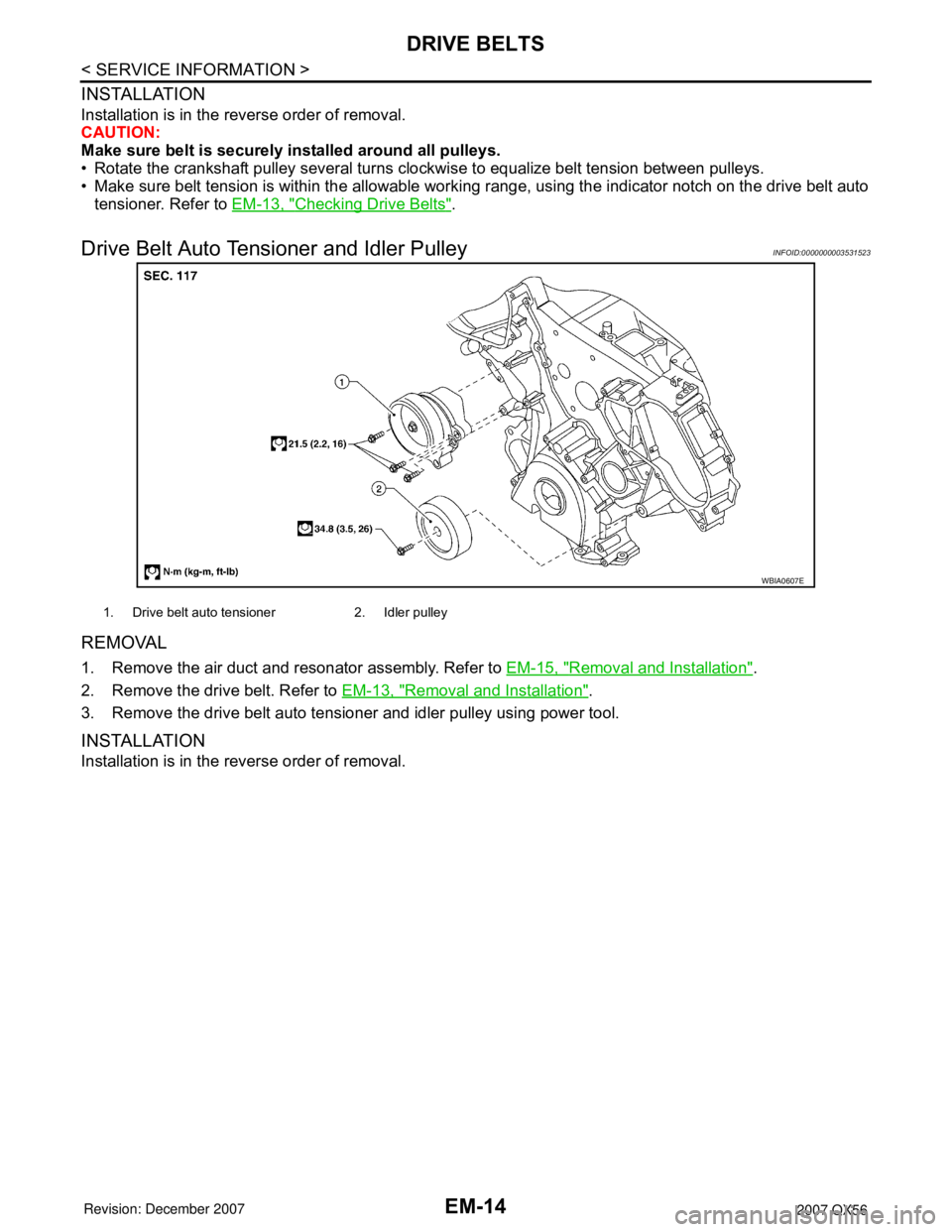
3. Remove the drive belt auto tensioner and idler pulley using power tool.
INSTALLATION
Installation is in the reverse order of removal.
WBIA0607E
1. Drive belt auto tensioner 2. Idler pulley
Page 1809 of 3061
TIMING CHAINEM-39
< SERVICE INFORMATION >
C
DE
F
G H
I
J
K L
M A
EM
NP
O
4. Obtain compression TDC of No. 1 cylinder as follows:
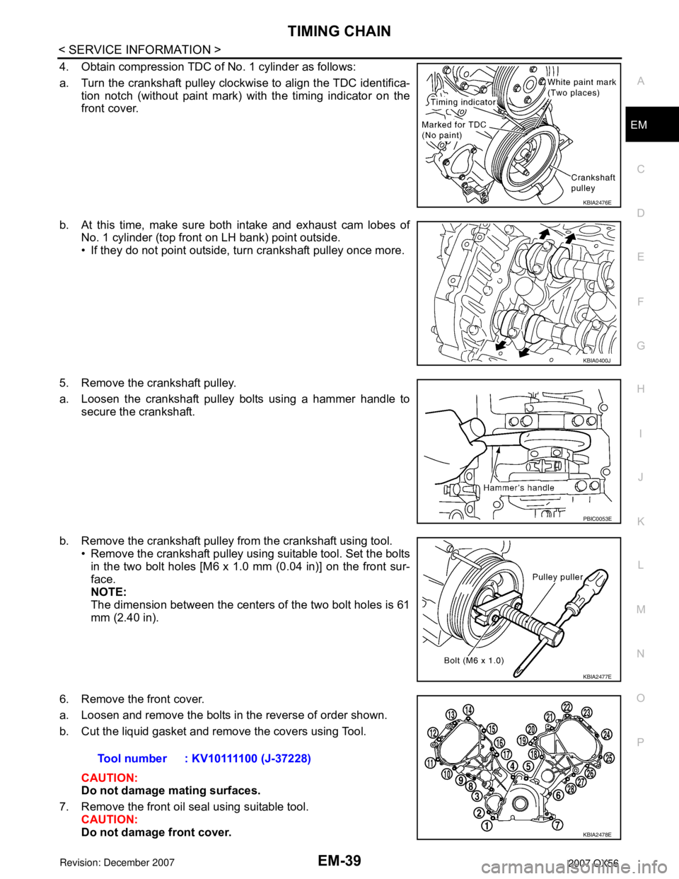
a. Turn the crankshaft pulley clockwise to align the TDC identifica-
tion notch (without paint mark) with the timing indicator on the
front cover.
b. At this time, make sure both intake and exhaust cam lobes of No. 1 cylinder (top front on LH bank) point outside.
• If they do not point outside, turn crankshaft pulley once more.
5. Remove the crankshaft pulley.
a. Loosen the crankshaft pulley bolts using a hammer handle to secure the crankshaft.
b. Remove the crankshaft pulley from the crankshaft using tool. • Remove the crankshaft pulley using suitable tool. Set the boltsin the two bolt holes [M6 x 1.0 mm (0.04 in)] on the front sur-
face.
NOTE:
The dimension between the centers of the two bolt holes is 61
mm (2.40 in).
6. Remove the front cover.
a. Loosen and remove the bolts in the reverse of order shown.
b. Cut the liquid gasket and remove the covers using Tool. CAUTION:
Do not damage mating surfaces.
7. Remove the front oil seal using suitable tool. CAUTION:
Do not damage front cover.
KBIA2476E
KBIA0400J
PBIC0053E
KBIA2477E
Tool number : KV10111100 (J-37228)
KBIA2478E
Page 1816 of 3061
EM-46
< SERVICE INFORMATION >
CAMSHAFT
CAMSHAFT
Removal and InstallationINFOID:0000000003531534
NOTE:
Do not remove the engine assembly to perform this procedure.
REMOVAL
1. Remove the RH bank and LH bank rocker covers. Refer to EM-35, "Removal and Installation".
2. Obtain compression TDC of No. 1 cylinder as follows:
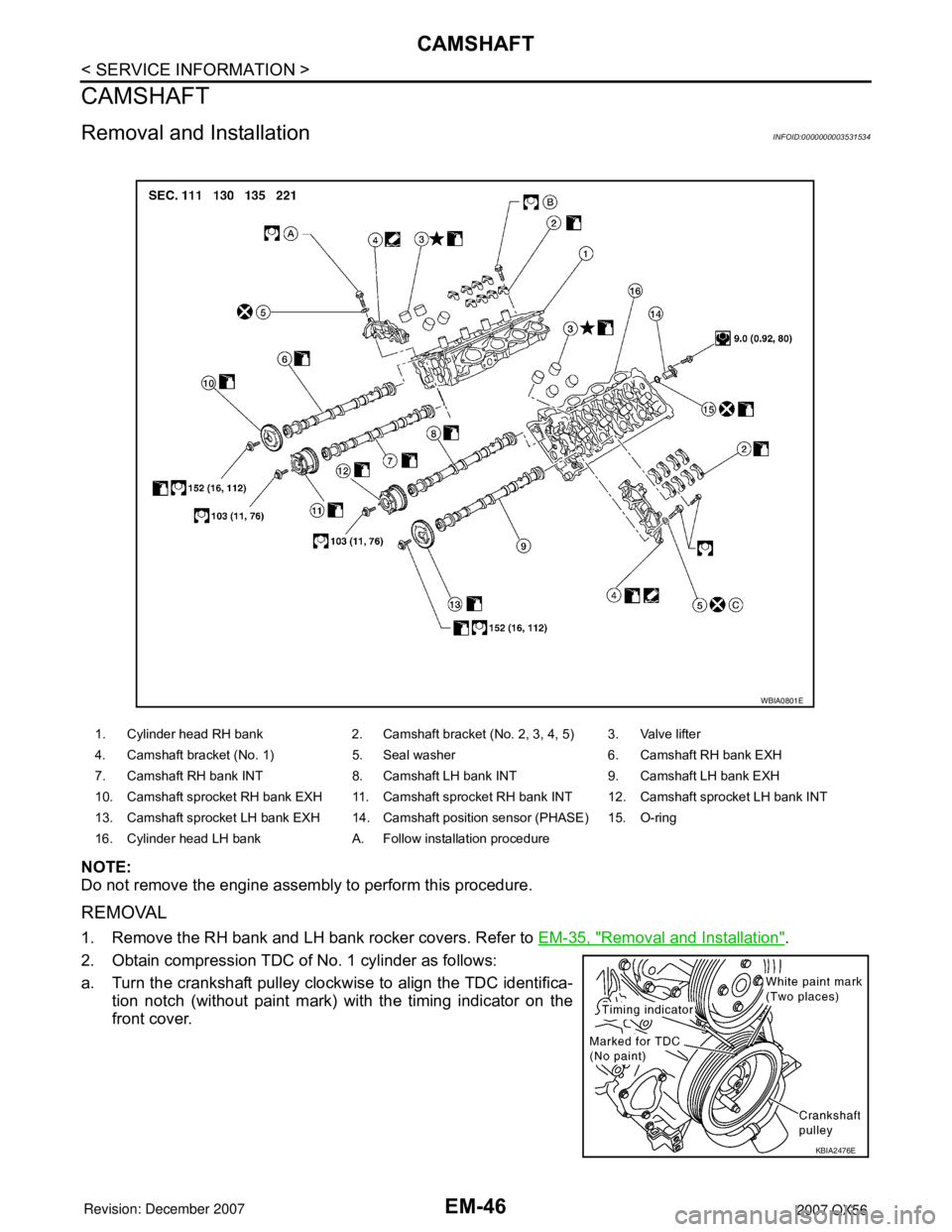
a. Turn the crankshaft pulley clockwise to align the TDC identifica- tion notch (without paint mark) with the timing indicator on the
front cover.
1. Cylinder head RH bank 2. Camshaft bracket (No. 2, 3, 4, 5) 3. Valve lifter
4. Camshaft bracket (No. 1) 5. Seal washer 6. Camshaft RH bank EXH
7. Camshaft RH bank INT 8. Camshaft LH bank INT 9. Camshaft LH bank EXH
10. Camshaft sprocket RH bank EXH 11. Camshaft sprocket RH bank INT 12. Camshaft sprocket LH bank INT
13. Camshaft sprocket LH bank EXH 14. Camshaft position sensor (PHASE) 15. O-ring
16. Cylinder head LH bank A. Follow installation procedure
WBIA0801E
KBIA2476E
Page 1820 of 3061
EM-50
< SERVICE INFORMATION >
CAMSHAFT
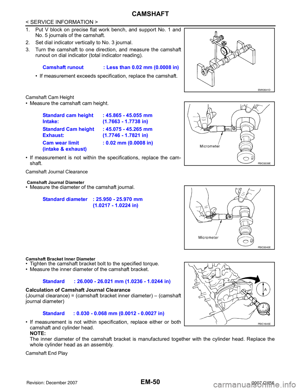
1. Put V block on precise flat work bench, and support No. 1 andNo. 5 journals of the camshaft.
2. Set dial indicator vertically to No. 3 journal.
3. Turn the camshaft to one direction, and measure the camshaft runout on dial indicator (total indicator reading).
• If measurement exceeds specif ication, replace the camshaft.
Camshaft Cam Height
• Measure the camshaft cam height.
• If measurement is not within the specifications, replace the cam-
shaft.
Camshaft Journal Clearance
Camshaft Journal Diameter• Measure the diameter of the camshaft journal.
Camshaft Bracket Inner Diameter• Tighten the camshaft bracket bolt to the specified torque.
• Measure the inner diameter of the camshaft bracket.
Calculation of Camshaft Journal Clearance
(Journal clearance) = (camshaft bracket inner diameter) – (camshaft
journal diameter)
• If measurement is not within spec ification, replace either or both
camshaft and cylinder head.
NOTE:
The inner diameter of the camshaft bracket is manuf actured together with the cylinder head. Replace the
whole cylinder head as an assembly.
Camshaft End Play
Camshaft runout : Less than 0.02 mm (0.0008 in)
EMK0641D
Standard cam height
Intake: : 45.865 - 45.055 mm
(1.7663 - 1.7738 in)
Standard Cam height
Exhaust: : 45.075 - 45.265 mm
(1.7746 - 1.7821 in)
Cam wear limit
(intake & exhaust) : 0.02 mm (0.0008 in)
PBIC0039E
Standard diameter : 25.950 - 25.970 mm
(1.0217 - 1.0224 in)
PBIC0040E
Standard : 26.000 - 26.021 mm (1.0236 - 1.0244 in)
Standard : 0.030 - 0.068 mm (0.0012 - 0.0027 in)
PBIC1645E
Page 1826 of 3061
EM-56
< SERVICE INFORMATION >
CAMSHAFT
2. Perform the following procedure so as to prevent the engine from being unintentionally started while
checking.
a. Release fuel pressure. Refer to EC-80, "
Fuel Pressure Check".
b. Disconnect ignition coil and injector harness connectors if practical.
3. Remove IVT control solenoid valve.
4. Crank engine, and then make sure that engine oil comes out from IVT control cover oil hole. End cranking
after checking.
WARNING:
Be careful not to touch rotating parts (drive be lts, idler pulley, and crankshaft pulley, etc.).
CAUTION:
• Engine oil may squirt from IVT control soleno id valve installation hole during cranking. Use a
shop cloth to prevent engine oil from splashin g on worker, engine components and vehicle.
• Do not allow engine oil to get on rubber compon ents such as drive belts or engine mount insula-
tors. Immediately wipe off any splashed engine oil.
5. Clean oil groove between oil strainer and IVT control solenoid valve if engine oil does not come out from IVT control valve cover oil hole. Refer to LU-7, "
Schematic".
6. Remove components between IVT control solenoid va lve and camshaft sprocket (INT), and then check
each oil groove for clogging.
• Clean oil groove if necessary.
7. After inspection, installation of the remaining components is in the reverse order of removal.
Valve ClearanceINFOID:0000000003531536
INSPECTION
NOTE:
Perform the following inspection after removal, installation or replacement of camshaft or valve-related parts,
or if there are unusual engine conditions due to changes in valve clearance over time (starting, idling, and/or
noise).
1. Warm up the engine. Then stop the engine.
2. Remove the engine cover and. Refer to EM-12, "
Removal and Installation".
3. Remove the battery cover. Refer to SC-8, "
Removal and Installation".
4. Remove the air cleaner and air duct assembly EM-15, "
Removal and Installation".
5. Remove the RH bank and LH bank rocker covers using power tool. Refer to EM-35, "
Removal and Instal-
lation".
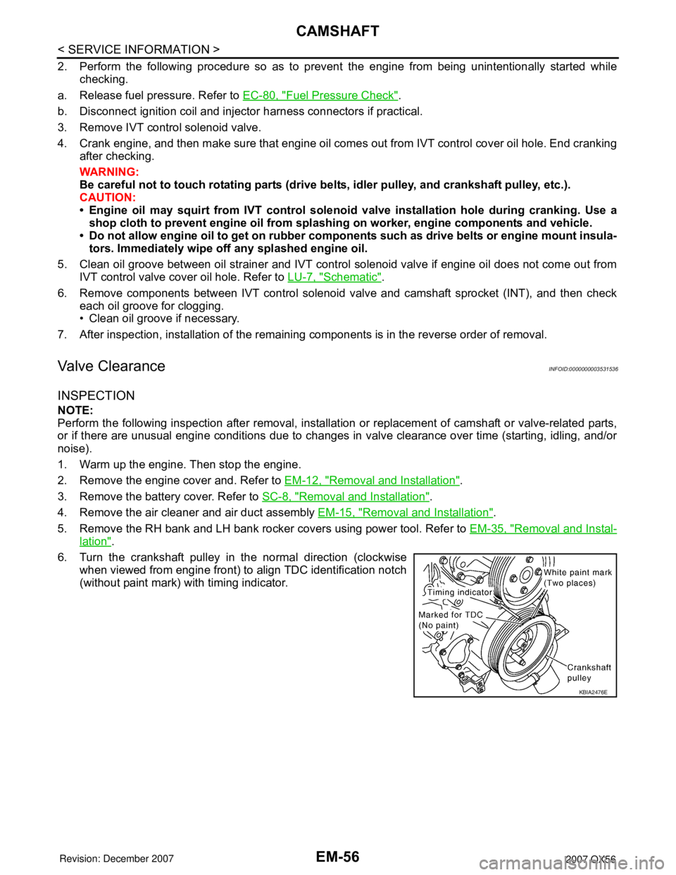
6. Turn the crankshaft pulley in the normal direction (clockwise when viewed from engine front) to align TDC identification notch
(without paint mark) with timing indicator.
KBIA2476E
Page 1845 of 3061
ENGINE ASSEMBLY
EM-75
< SERVICE INFORMATION >
C
D
E
F
G
H
I
J
K
L
MA
EM
N
P O
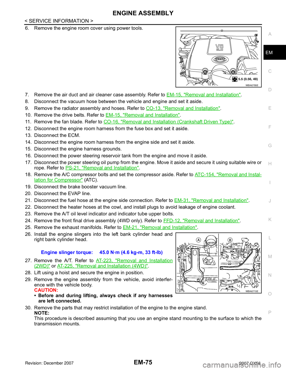
6. Remove the engine room cover using power tools.
7. Remove the air duct and air cleaner case assembly. Refer to EM-15, "
Removal and Installation".
8. Disconnect the vacuum hose between the vehicle and engine and set it aside.
9. Remove the radiator assembly and hoses. Refer to CO-13, "
Removal and Installation".
10. Remove the drive belts. Refer to EM-15, "
Removal and Installation".
11. Remove the fan blade. Refer to CO-16, "
Removal and Installation (Crankshaft Driven Type)".
12. Disconnect the engine room harness from the fuse box and set it aside.
13. Disconnect the ECM.
14. Disconnect the engine room harness from the engine side and set it aside.
15. Disconnect the engine harness grounds.
16. Disconnect the power steering reservoir tank from the engine and move it aside.
17. Disconnect the power steering oil pump from the engine. Move it aside and secure it using suitable wire or
rope. Refer to PS-21, "
Removal and Installation".
18. Remove the A/C compressor bolts and set the compressor aside. Refer to ATC-154, "
Removal and Instal-
lation for Compressor" (ATC).
19. Disconnect the brake booster vacuum line.
20. Disconnect the EVAP line.
21. Disconnect the fuel hose at the engine side connection. Refer to EM-31, "
Removal and Installation".
22. Disconnect the heater hoses at the cowl, and install plugs to avoid leakage of engine coolant.
23. Remove the A/T oil level indicator and indicator tube upper bolts.
24. Remove the front final drive assembly (4WD only). Refer to FFD-12, "
Removal and Installation".
25. Remove the exhaust manifolds. Refer to EM-21, "
Removal and Installation".
26. Install the engine slingers into the left bank cylinder head and
right bank cylinder head.
27. Remove the A/T. Refer to AT-223, "
Removal and Installation
(2WD)" or AT-225, "Removal and Installation (4WD)".
28. Lift using a hoist and secure the engine in position.
29. Remove the engine assembly from the vehicle, avoid interfer-
ence with the vehicle body.
CAUTION:
• Before and during lifting, always check if any harnesses
are left connected.
30. Remove the parts that may restrict installation of the engine to the engine stand.
NOTE:
This procedure is described assuming that you use an engine stand mounting to the surface to which the
transmission mounts.
WBIA0795E
Engine slinger torque: 45.0 N·m (4.6 kg-m, 33 ft-lb)
WBIA0715E
Page 1874 of 3061
EM-104
< SERVICE INFORMATION >
SERVICE DATA AND SPECIFICATIONS (SDS)
Unit: mm (in)
SPARK PLUG
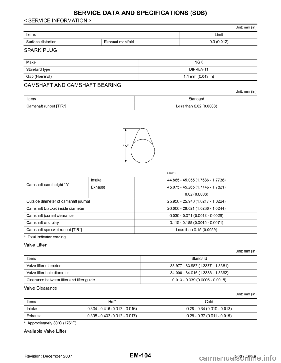
CAMSHAFT AND CAMSHAFT BEARING
Unit: mm (in)
*: Total indicator reading
Valve Lifter
Unit: mm (in)
Valve Clearance
Unit: mm (in)
*: Approximately 80°C (176°F)
Available Valve Lifter
ItemsLimit
Surface distortion Exhaust manifold 0.3 (0.012)
MakeNGK
Standard typeDIFR5A-11
Gap (Nominal)1.1 mm (0.043 in)
ItemsStandard
Camshaft runout [TIR*] Less than 0.02 (0.0008)
Camshaft cam height “A”Intake 44.865 - 45.055 (1.7636 - 1.7738)
Exhaust 45.075 - 45.265 (1.7746 - 1.7821)
0.02 (0.0008)
Outside diameter of camshaft journal 25.950 - 25.970 (1.0217 - 1.0224)
Camshaft bracket inside diameter 26.000 - 26.021 (1.0236 - 1.0244)
Camshaft journal clearance 0.030 - 0.071 (0.0012 - 0.0028)
Camshaft end play 0.115 - 0.188 (0.0045 - 0.0074)
Camshaft sprocket runout [TIR*] Less than 0.15 (0.0059)
SEM671
ItemsStandard
Valve lifter diameter 33.977 - 33.987 (1.3377 - 1.3381)
Valve lifter hole diameter 34.000 - 34.016 (1.3386 - 1.3392)
Clearance between lifter and lifter guide 0.013 - 0.039 (0.0005 - 0.0015)
Items Hot* Cold
Intake 0.304 - 0.416 (0.012 - 0.016) 0.26 - 0.34 (0.010 - 0.013)
Exhaust 0.308 - 0.432 (0.012 - 0.017) 0.29 - 0.37 (0.011 - 0.015)