Page 280 of 3061

AT-210
< SERVICE INFORMATION >
ON-VEHICLE SERVICE
2. Install the oil pan (2) and new oil pan gasket.
• Oil pan clips (1)
• Drain plug (3)
• : Front
• : Oil pan bolts
CAUTION:
• Do not reuse the oil pan gasket.
• Completely remove all moisture, oil and old gasket from
the oil pan gasket mating surfaces and holes.
• Always replace the oil pan bolts as they are self-sealing.
• Be sure the oil pan drain plug hole is located to the rear of
the transmission assembly.
• Partially install the oil pan bolts in a criss-cross pattern to prevent dislocation of the gasket.
• Be careful not to pinch harnesses.
3. Tighten new oil pan bolts in numerical order as shown.
4. Install drain plug in oil pan with new gasket.
CAUTION:
Do not reuse the drain plug gasket.
5. Refill the transmission assembly with fluid. Refer to AT-13, "
Changing Automatic Transmission Fluid
(ATF)".
Control Valve with TCM and A/T Fluid Temperature Sensor 2INFOID:0000000003532478
COMPONENTS
AWDIA0023ZZ
Oil pan bolts : 7.9 N·m (0.81 kg-m, 70 in-lb)
SCIA4113E
Drain plug : 34 N·m (3.5 kg-m, 25 ft-lb)
Page 367 of 3061

ASSEMBLY
AT-297
< SERVICE INFORMATION >
D
E
F
G
H
I
J
K
L
MA
B
AT
N
O
P
17. Install the oil pan and new oil pan gasket. Refer to AT-209, "Oil Pan".
CAUTION:
• Do not reuse the oil pan gasket.
• Completely remove all moisture, oil and old gasket from the oil pan gasket mating surfaces and
holes.
• Always replace the oil pan bolts as they are self-sealing.
• Be sure the oil pan drain plug hole is located to the rear of the transmission assembly.
• Partially install the oil pan bolts in a criss-cross pattern to prevent dislocation of the gasket.
• Be careful not to pinch harnesses.
18. Install drain plug in oil pan with new gasket.
CAUTION:
Do not reuse the drain plug gasket.
19. Install torque converter.
a. Pour ATF into torque converter.
•Approximately 2 liter (2-1/8 US qt, 1-3/4 Imp qt) of fluid is
required for a new torque converter.
•When reusing old torque converter, add the same amount
of fluid as was drained.
b. Install torque converter while aligning notches of torque con-
verter with notches of oil pump.
CAUTION:
Install torque converter while rotating it.
c. Measure distance “A” to check that torque converter is in proper
position.Drain plug : 34 N·m (3.5 kg-m, 25 ft-lb)
SAT428DA
SCIA5010E
Distance “A” : 24.0 mm (0.94 in) or more
SAT017B
Page 1927 of 3061

FFD-28
< SERVICE INFORMATION >
FRONT FINAL DRIVE ASSEMBLY
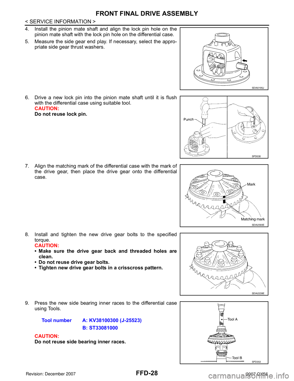
4. Install the pinion mate shaft and align the lock pin hole on the
pinion mate shaft with the lock pin hole on the differential case.
5. Measure the side gear end play. If necessary, select the appro-
priate side gear thrust washers.
6. Drive a new lock pin into the pinion mate shaft until it is flush
with the differential case using suitable tool.
CAUTION:
Do not reuse lock pin.
7. Align the matching mark of the differential case with the mark of
the drive gear, then place the drive gear onto the differential
case.
8. Install and tighten the new drive gear bolts to the specified
torque.
CAUTION:
• Make sure the drive gear back and threaded holes are
clean.
• Do not reuse drive gear bolts.
• Tighten new drive gear bolts in a crisscross pattern.
9. Press the new side bearing inner races to the differential case
using Tools.
CAUTION:
Do not reuse side bearing inner races.
SDIA0195J
SPD030
SDIA2593E
SDIA2239E
Tool number A: KV38100300 (J-25523)
B: ST33081000
SPD353
Page 2586 of 3061

REAR FINAL DRIVE ASSEMBLY
RFD-29
< SERVICE INFORMATION >
C
E
F
G
H
I
J
K
L
MA
B
RFD
N
O
P
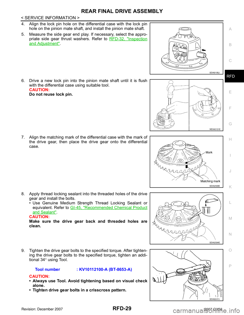
4. Align the lock pin hole on the differential case with the lock pin
hole on the pinion mate shaft, and install the pinion mate shaft.
5. Measure the side gear end play. If necessary, select the appro-
priate side gear thrust washers. Refer to RFD-32, "
Inspection
and Adjustment".
6. Drive a new lock pin into the pinion mate shaft until it is flush
with the differential case using suitable tool.
CAUTION:
Do not reuse lock pin.
7. Align the matching mark of the differential case with the mark of
the drive gear, then place the drive gear onto the differential
case.
8. Apply thread locking sealant into the threaded holes of the drive
gear and install the bolts.
• Use Genuine Medium Strength Thread Locking Sealant or
equivalent. Refer to GI-45, "
Recommended Chemical Product
and Sealant".
CAUTION:
Make sure the drive gear back and threaded holes are
clean.
9. Tighten the drive gear bolts to the specified torque. After tighten-
ing the drive gear bolts to the specified torque, tighten an addi-
tional 34° using Tool.
CAUTION:
• Always use Tool. Avoid tightening based on visual check
alone.
• Tighten drive gear bolts in a crisscross pattern.
SDIA0195J
WDIA0131E
SDIA2593E
SDIA2594E
Tool number : KV10112100-A (BT-8653-A)
SDIA0247J