2007 INFINITI QX56 service indicator
[x] Cancel search: service indicatorPage 962 of 3061
![INFINITI QX56 2007 Factory Service Manual BRC-34
< SERVICE INFORMATION >[VDC/TCS/ABS]
TROUBLE DIAGNOSIS FOR SELF-DIAGNOSTIC ITEMS
TROUBLE DIAGNOSIS FOR SELF-DIAGNOSTIC ITEMS
Wheel Sensor System InspectionINFOID:0000000003532784
INSPECTION PRO INFINITI QX56 2007 Factory Service Manual BRC-34
< SERVICE INFORMATION >[VDC/TCS/ABS]
TROUBLE DIAGNOSIS FOR SELF-DIAGNOSTIC ITEMS
TROUBLE DIAGNOSIS FOR SELF-DIAGNOSTIC ITEMS
Wheel Sensor System InspectionINFOID:0000000003532784
INSPECTION PRO](/manual-img/42/57029/w960_57029-961.png)
BRC-34
< SERVICE INFORMATION >[VDC/TCS/ABS]
TROUBLE DIAGNOSIS FOR SELF-DIAGNOSTIC ITEMS
TROUBLE DIAGNOSIS FOR SELF-DIAGNOSTIC ITEMS
Wheel Sensor System InspectionINFOID:0000000003532784
INSPECTION PROCEDURE
1.CONNECTOR INSPECTION
Disconnect the ABS actuator and electric unit (control unit) connector E125 and wheel sensor of malfunction-
ing code.
Check the terminals for deformation, disconnection, looseness or damage.
OK or NG
OK >> GO TO 2.
NG >> Repair or replace as necessary.
2.CHECK WHEEL SENSOR OUTPUT SIGNAL
1. Connect ABS active wheel sensor tester (J-45741) to wheel sensor using appropriate adapter.
2. Turn on the ABS active wheel sensor tester power switch.
NOTE:
The green POWER indicator should illuminate. If the POWER indicator does not illuminate, replace the
battery in the ABS active wheel sensor tester before proceeding.
3. Spin the wheel of the vehicle by hand and observe the red SENSOR indicator on the ABS active wheel
sensor tester. The red SENSOR indicator should flash on and off to indicate an output signal.
NOTE:
If the red SENSOR indicator illuminates but does not flash, reverse the polarity of the tester leads and
retest.
Does the ABS active wheel sensor tester detect a signal?
YES >> GO TO 3.
NO >> Replace the wheel sensor. Refer to BRC-56, "
Removal and Installation".
3.CHECK TIRES
Check for inflation pressure, wear and size of each tire.
Are tire pressure and size correct and is tire wear within specifications?
YES >> GO TO 4.
NO >> Adjust tire pressure or replace tire(s).
4.CHECK WHEEL BEARINGS
Check wheel bearing axial end play. Refer to FAX-5, "
On-Vehicle Inspection and Service" (front) or RAX-5,
"On-Vehicle Inspection and Service" (rear).
OK or NG
OK >> GO TO 5.
NG >> Repair or replace as necessary. Refer to FAX-5, "
On-Vehicle Inspection and Service" (front) or
RAX-5, "
On-Vehicle Inspection and Service" (rear).
5.CHECK WIRING HARNESS FOR SHORT CIRCUIT
1. Disconnect ABS actuator and electric unit (control unit) connec-
tor and wheel sensor connector of malfunction code No.
2. Check continuity between wheel sensor harness connector ter-
minals and ground.
OK or NG
OK >> GO TO 6.
NG >> Repair the circuit.
6.CHECK WIRING HARNESS FOR OPEN CIRCUITContinuity should not exist.
WFIA0343E
Page 975 of 3061
![INFINITI QX56 2007 Factory Service Manual TROUBLE DIAGNOSIS FOR SELF-DIAGNOSTIC ITEMS
BRC-47
< SERVICE INFORMATION >[VDC/TCS/ABS]
C
D
E
G
H
I
J
K
L
MA
B
BRC
N
O
P
2. Measure the continuity between the ABS actuator and electric unit (control u INFINITI QX56 2007 Factory Service Manual TROUBLE DIAGNOSIS FOR SELF-DIAGNOSTIC ITEMS
BRC-47
< SERVICE INFORMATION >[VDC/TCS/ABS]
C
D
E
G
H
I
J
K
L
MA
B
BRC
N
O
P
2. Measure the continuity between the ABS actuator and electric unit (control u](/manual-img/42/57029/w960_57029-974.png)
TROUBLE DIAGNOSIS FOR SELF-DIAGNOSTIC ITEMS
BRC-47
< SERVICE INFORMATION >[VDC/TCS/ABS]
C
D
E
G
H
I
J
K
L
MA
B
BRC
N
O
P
2. Measure the continuity between the ABS actuator and electric unit (control unit) connector E125 and body
ground.
OK or NG
OK >> GO TO 4.
NG >> Repair or replace harness or connector.
4.REAR PRESSURE SENSOR INSPECTION
1. Reconnect the rear pressure sensor and ABS actuator and electric unit (control unit) connectors.
2. Use "DATA MONITOR" to check if the status of "PRESS SEN 2" is normal.
OK or NG
OK >> Inspection End.
NG >> Replace rear pressure sensor.
Steering Angle Sensor Safe Mode InspectionINFOID:0000000003532797
INSPECTION PROCEDURE
1.INDICATOR LAMP CHECK
Check that VDC OFF indicator lamp is on.
OK or NG
OK >> GO TO 2.
NG >> GO TO 3.
2.ADJUSTMENT OF STEERING ANGLE SENSOR NEUTRAL POSITION
Adjust steering angle sensor neutral position. Refer to BRC-54, "
Adjustment of Steering Angle Sensor Neutral
Position".
OK or NG
OK >> GO TO 3.
NG >> Check steering angle sensor. Refer to BRC-36, "
Steering Angle Sensor System".
3.INDICATOR LAMP CHECK
Check that VDC OFF indicator lamp is off.
OK or NG
OK >> GO TO 4.
NG >> Perform basic inspection. Refer to BRC-22, "
Basic Inspection".
4.CHECK SELF-DIAGNOSTIC RESULTS
Perform ABS actuator and electric unit (control unit) self-diagnosis.
NOTE:ABS actuator and electric unit (con-
trol unit) connector E125Body ground Continuity
21
—No 22
23
ConditionData monitor display (Approx.)
PRESS SEN 2
When brake pedal is depressed Positive value
When brake pedal is released 0 bar
Self-diagnosis results
ST ANGL SEN SAFE
Page 1012 of 3061

DI-1
ELECTRICAL
C
DE
F
G H
I
J
L
M
SECTION DI
A
B
DI
N
O P
CONTENTS
DRIVER INFORMATION SYSTEM
SERVICE INFORMATION .. ..........................3
PRECAUTION ................................................ .....3
Precaution for Supplemental Restraint System
(SRS) "AIR BAG" and "SEAT BELT PRE-TEN-
SIONER" ............................................................. ......
3
PREPARATION ...................................................4
Commercial Service Tool .................................... ......4
COMBINATION METERS ...................................5
Component Parts and Harness Connector Loca-
tion ...................................................................... ......
5
System Description ...................................................5
Arrangement of Combination Meter ..........................7
Internal Circuit ...........................................................8
Wiring Diagram - METER - .......................................9
Combination Meter Harness Connector Terminal
Layout .....................................................................
11
Terminal and Reference Value for Combination
Meter .......................................................................
11
Self-Diagnosis Mode of Combination Meter ........ ....12
How to Proceed with Trouble Diagnosis ............. ....15
Preliminary Check ...................................................15
Symptom Chart .......................................................16
Power Supply and Ground Circuit Inspection .........16
Vehicle Speed Signal Inspection .............................17
Engine Oil Pressure Signal Inspection ....................17
Water Temperature Signal Inspection .....................18
Engine Speed Signal Inspection ......................... ....18
Fuel Level Sensor Unit Inspection ...................... ....18
Fuel Gauge Fluctuates, Indicates Wrong Value, or
Varies .................................................................. ....
20
Fuel Gauge Does Not Move to Full-position ...........20
Electrical Component Inspection ......................... ....21
Removal and Installation of Combination Meter .....21
COMPASS AND THERMOMETER ................ ....22
System Description ............................................. ....22
Wiring Diagram - COMPAS - ..................................23
Trouble Diagnosis ............................................... ....23
Calibration Procedure for Compass .................... ....24
WARNING LAMPS ............................................26
Schematic ............................................................ ....26
Wiring Diagram - WARN - .......................................27
Oil Pressure Warning Lamp Stays Off (Ignition
Switch ON) .......................................................... ....
32
Oil Pressure Warning Lamp Does Not Turn Off
(Oil Pressure Is Normal) ...................................... ....
33
A/T INDICATOR ................................................34
Wiring Diagram - AT/IND - .......................................34
A/T Indicator Does Not Illuminate ............................34
WARNING CHIME .............................................36
Component Parts and Harness Connector Loca-
tion ....................................................................... ....
36
System Description ..................................................36
CAN Communication System Description ...............37
Wiring Diagram - CHIME - .......................................38
Terminal and Reference Value for BCM ..................39
Terminal and Reference Value for Combination
Meter ................................................................... ....
39
How to Proceed with Trouble Diagnosis ..................40
Preliminary Check ............................................... ....40
CONSULT-II Function (BCM) ..................................40
All Warning Chimes Do Not Operate .......................41
Key Warning Chime and Light Warning Chime Do
Not Operate (Seat Belt Warning Chime Does Op-
erate) .......................................................................
41
Key Warning Chime Does Not Operate ...................42
Light Warning Chime Does Not Operate .................44
Seat Belt Warning Chime Does Not Operate ..........44
REAR SONAR SYSTEM ...................................46
Component Parts and Harness Connector Loca-
tion ....................................................................... ....
46
System Description ..................................................46
Wiring Diagram - SONAR - ......................................48
Sonar Control Unit Harness Connector Terminal
Layout ......................................................................
50
Page 1016 of 3061

COMBINATION METERSDI-5
< SERVICE INFORMATION >
C
DE
F
G H
I
J
L
M A
B
DI
N
O P
COMBINATION METERS
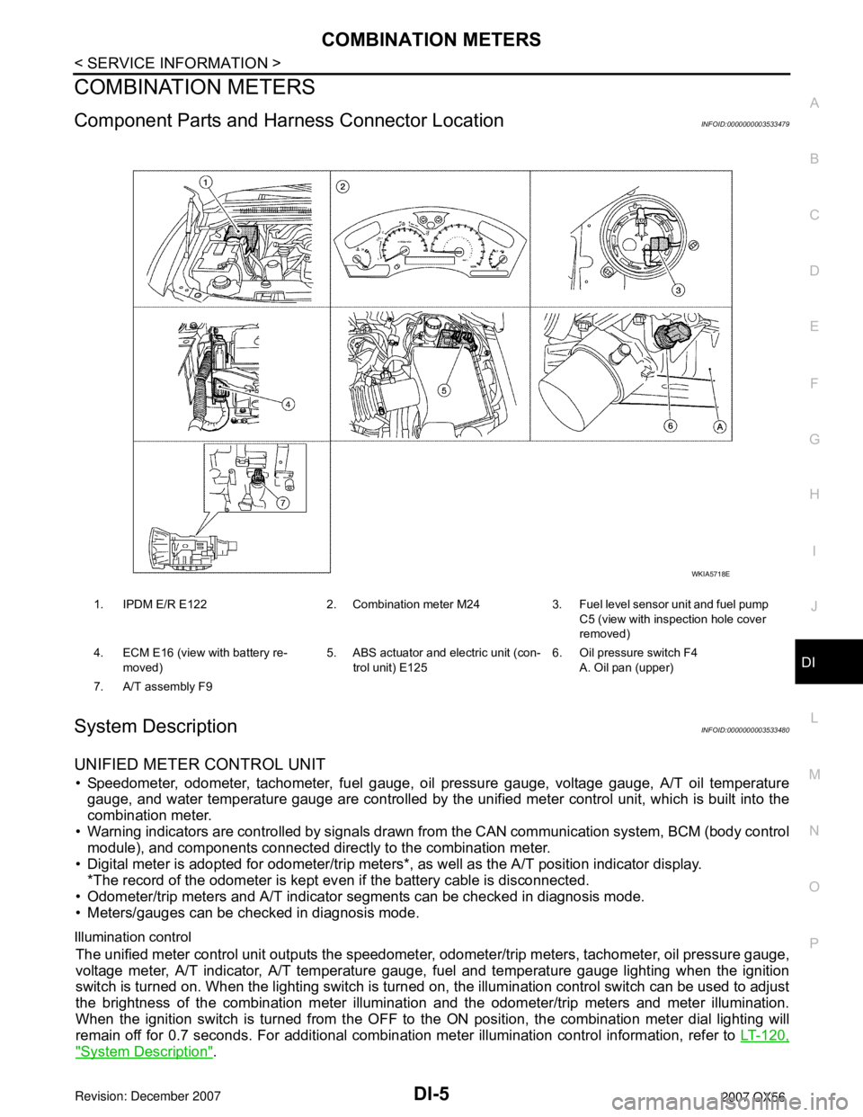
Component Parts and Har ness Connector LocationINFOID:0000000003533479
System DescriptionINFOID:0000000003533480
UNIFIED METER CONTROL UNIT
• Speedometer, odometer, tachometer, fuel gauge, oil pressure gauge, voltage gauge, A/T oil temperature
gauge, and water temperature gauge are controlled by the unified meter control unit, which is built into the
combination meter.
• Warning indicators are controlled by signals drawn fr om the CAN communication system, BCM (body control
module), and components connected directly to the combination meter.
• Digital meter is adopted for odometer/trip meters*, as well as the A/T position indicator display. *The record of the odometer is kept ev en if the battery cable is disconnected.
• Odometer/trip meters and A/T indicator segments can be checked in diagnosis mode.
• Meters/gauges can be checked in diagnosis mode.
Illumination control
The unified meter control unit outputs the speedometer, odometer/trip meters, tachometer, oil pressure gauge,
voltage meter, A/T indicator, A/T temperature gauge, fuel and temperature gauge lighting when the ignition
switch is turned on. When the lighting switch is turned on, the illumination control switch can be used to adjust
the brightness of the combination meter illuminati on and the odometer/trip meters and meter illumination.
When the ignition switch is turned from the OFF to the ON position, the combination meter dial lighting will
remain off for 0.7 seconds. For additional combination meter illumination control information, refer to LT-120,
"System Description".
1. IPDM E/R E122 2. Combination meter M24 3. Fuel level sensor unit and fuel pump
C5 (view with inspection hole cover
removed)
4. ECM E16 (view with battery re- moved) 5. ABS actuator and electric unit (con-
trol unit) E125 6. Oil pressure switch F4
A. Oil pan (upper)
7. A/T assembly F9
WKIA5718E
Page 1022 of 3061

COMBINATION METERSDI-11
< SERVICE INFORMATION >
C
DE
F
G H
I
J
L
M A
B
DI
N
O P
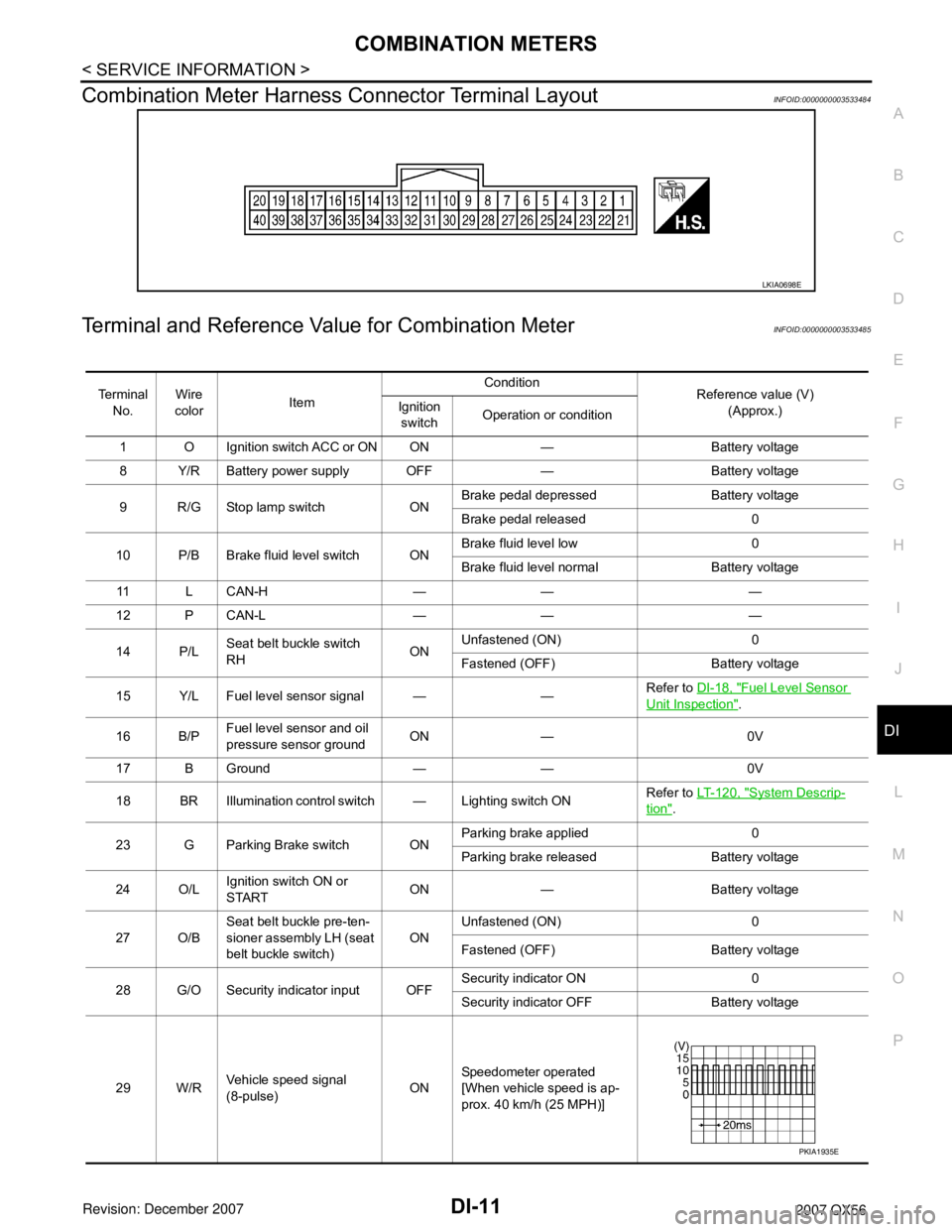
Combination Meter Harness Connector Terminal LayoutINFOID:0000000003533484
Terminal and Reference Va lue for Combination MeterINFOID:0000000003533485
LKIA0698E
Te r m i n a l
No. Wire
color Item Condition
Reference value (V)
(Approx.)
Ignition
switch Operation or condition
1 O Ignition switch ACC or ON ON — Battery voltage
8 Y/R Battery power supply OFF — Battery voltage
9 R/G Stop lamp switch ON Brake pedal depressed Battery voltage
Brake pedal released 0
10 P/B Brake fluid level switch ON Brake fluid level low 0
Brake fluid level normal Battery voltage
11 L C A N - H — — —
12 P CAN-L — — —
14 P/L Seat belt buckle switch
RH ONUnfastened (ON) 0
Fastened (OFF) Battery voltage
15 Y/L Fuel level sensor signal — — Refer to
DI-18, "
Fuel Level Sensor
Unit Inspection".
16 B/P Fuel level sensor and oil
pressure sensor ground ON — 0V
17 B Ground — — 0V
18 BR Illumination control switch — Lighting switch ON Refer to
LT- 1 2 0 , "
System Descrip-
tion".
23 G Parking Brake switch ON Parking brake applied 0
Parking brake released Battery voltage
24 O/L Ignition switch ON or
START ON — Battery voltage
27 O/B Seat belt buckle pre-ten-
sioner assembly LH (seat
belt buckle switch) ON
Unfastened (ON) 0
Fastened (OFF) Battery voltage
28 G/O Security indicator input OFF Security indicator ON 0
Security indicator
OFF Battery voltage
29 W/R Vehicle speed signal
(8-pulse) ONSpeedometer operated
[When vehicle speed is ap-
prox. 40 km/h (25 MPH)]
PKIA1935E
Page 1026 of 3061

COMBINATION METERSDI-15
< SERVICE INFORMATION >
C
DE
F
G H
I
J
L
M A
B
DI
N
O P
How to Proceed with Trouble DiagnosisINFOID:0000000003533487
1. Confirm the symptom or customer complaint.
2. Perform preliminary check. Refer to DI-15, "
Preliminary Check".
3. According to the symptom chart, repair or replace the cause of the symptom.
4. Does the meter operate normally? If so, go to 5. If not, go to 2.
5. Inspection End.
Preliminary CheckINFOID:0000000003533488
1.CHECK WARNING INDICATOR ILLUMINATION
1. Turn ignition switch ON.
2. Make sure warning indicators (such as malfunction indicator lamp and oil pressure low/coolant tempera- ture high warning indicator) illuminate.
Do warning indicators illuminate?
YES >> GO TO 2.
NO >> Check ignition power supply system of combination meter. Refer to DI-16, "
Power Supply and
Ground Circuit Inspection".
2.CHECK OPERATION OF SELF-DIAGNOSIS MODE (COMBINATION METER)
Next test requested A04XXXA/D port A/D value (non-
ratioed).0-255
Next test requested A05XXX A/D port A/D value (non-
ratioed).
0-255
Next test requested A06XXX A/D port A/D value (non-
ratioed).0-255
Next test requested A07XXX A/D port A/D value (non-
ratioed).0-255
Next test requested A08XXX A/D port A/D value (non-
ratioed).
0-255
Next test requested A09XXX A/D port A/D value (non-
ratioed).0-255
Next test requested A10XXX A/D port A/D value (non-
ratioed).0-255
Next test requested A11XXX A/D port A/D value (non-
ratioed).
0-255
Next test requested A12XXX A/D port A/D value (non-
ratioed).0-255
Next test requested A13XXX A/D port A/D value (non-
ratioed).0-255
Next test requested A14XXX A/D port A/D value (non-
ratioed).
0-255
Next test requested A15XXX A/D port A/D value (non-
ratioed).0-255
Next test requested PA0-XX Hex value representing
state of A/D ports 0-7.
Next test requested PA1-XX Hex value representing
state of A/D ports 0-7.
Next test requested Thr-XXX Decimal value of ther-
mistor A/D reading.0-255
Next test requested rXXXX, FAIL Return to beginning of self-di-
agnosis.
Event Odometer Display Description of Test/Data Notes:
Page 1045 of 3061

DI-34
< SERVICE INFORMATION >
A/T INDICATOR
A/T INDICATOR
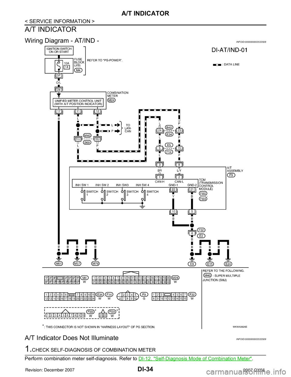
Wiring Diagram - AT/IND -INFOID:0000000003533508
A/T Indicator Does Not IlluminateINFOID:0000000003533509
1.CHECK SELF-DIAGNOSIS OF COMBINATION METER
Perform combination meter self-diagnosis. Refer to DI-12, "
Self-Diagnosis Mode of Combination Meter".
WKWA3626E
Page 1046 of 3061

A/T INDICATOR
DI-35
< SERVICE INFORMATION >
C
D
E
F
G
H
I
J
L
MA
B
DI
N
O
P
OK or NG
OK >> GO TO 2.
NG >> Replace the combination meter. Refer to IP-10, "
Removal and Installation".
2.CHECK TCM
Perform self-diagnosis of TCM. Refer to AT-83, "
CONSULT-II Function (A/T)".
OK or NG
OK >> Replace the combination meter. Refer to IP-10, "Removal and Installation".
NG >> Refer to AT-83, "
CONSULT-II Function (A/T)".