2007 INFINITI QX56 service indicator
[x] Cancel search: service indicatorPage 1058 of 3061
REAR SONAR SYSTEM
DI-47
< SERVICE INFORMATION >
C
D
E
F
G
H
I
J
L
MA
B
DI
N
O
P
Ground is supplied
• to sonar control unit terminal 6
• through body grounds B7 and B19.
With the ignition switch in the ON or START position, and the transmission gear selector lever in the R posi-
tion, power is supplied
• to sonar control unit terminal 5
• from back-up lamp relay terminal 5.
With power and ground supplied, transmission gear selector lever in R position, and the rear sonar system
OFF switch ON, the rear sonar system will detect obstacles within 1.8 m (5.9 ft.) of the rear sonar sensors. The
vehicle operator is notified of obstacles by varied rate of tone from the sonar buzzer depending on distance of
obstacle being sensed.
REAR SONAR SYSTEM OFF SWITCH
With power and ground supplied to the sonar control unit, transmission gear selector lever in R position, the
sonar system can be disabled and the sonar buzzer silenced by momentarily pressing the rear sonar system
OFF switch. The rear sonar system OFF indicator lamp will be illuminated in the rear sonar system OFF
switch.
To disable the rear sonar system, ground is supplied
• to sonar control unit terminal 13
• through rear sonar system OFF switch terminal 1
• through rear sonar system OFF switch terminal 2
• from body grounds M57, M61, and M79.
To light the rear sonar system OFF indicator, power is supplied
• from sonar control unit terminal 4
• to the rear sonar system OFF switch terminal 5.
Ground is supplied
• to the rear sonar system OFF switch terminal 6
• from body grounds M57, M61, and M79.
The rear sonar system and buzzer will be disabled and the rear sonar system OFF indicator will be illuminated
until the ignition switch is turned OFF. When the ignition switch is turned ON, the rear sonar system will be
enabled. Depressing the rear sonar system OFF switch momentarily will enable the rear sonar system also.
Enabling the rear sonar system will cause the rear sonar system OFF indicator to go out.
SONAR BUZZER
With power supplied to the sonar control unit and the transmission gear selector lever in R position, a station-
ary object that is at least 7.0 cm (2.8 in.) wide and 1.0 m (39.0 in.) tall and that is closer than 1.8 meters (5.9 ft.)
will be detected by the rear sonar sensors, causing the sonar buzzer to sound a tone. As the vehicle moves
closer to the object, the rate of the tone will increase. When the object is less than 25.0 cm (10 in.) from the
rear bumper, the tone will sound continuously.
Power is supplied
• from sonar control unit terminal 7
• to sonar buzzer terminal +.
Ground is supplied
• to sonar buzzer terminal -
• from sonar control unit terminal 3.
REAR SONAR SENSOR
With power and ground supplied to the rear sonar sensors, the sonar sensors transmit a 38.4 kHz ultrasonic
signal. This signal is reflected back to the sensor by objects large enough and close enough to be detected.
The rear sonar sensors measure the time from the transmitted signal to the time the signal is reflected back
and sends this information to the sonar control unit.
Power is supplied
• from sonar control unit terminal 16
• to each rear sonar sensor terminal 1.
Ground is supplied
• to each rear sonar sensor terminal 3
• from sonar control unit terminal 15.
Signal is supplied
• from each rear sonar sensor terminal 2
• to sonar control unit terminals 9, 10, 11 and 12.
Page 1061 of 3061
DI-50
< SERVICE INFORMATION >
REAR SONAR SYSTEM
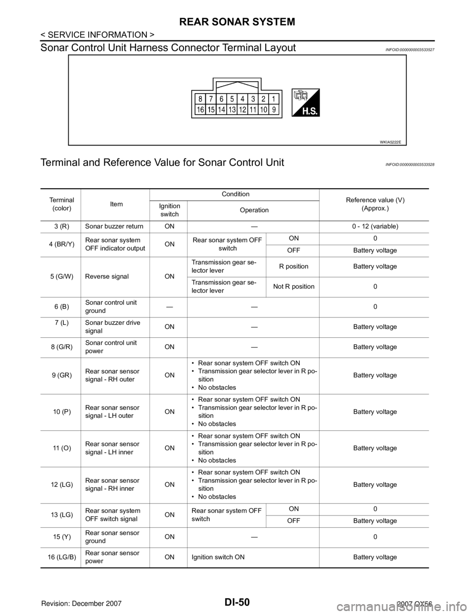
Sonar Control Unit Harness Connector Terminal Layout
INFOID:0000000003533527
Terminal and Reference Value for Sonar Control UnitINFOID:0000000003533528
WKIA5222E
Te r m i n a l
(color)ItemCondition
Reference value (V)
(Approx.) Ignition
switchOperation
3 (R) Sonar buzzer return ON — 0 - 12 (variable)
4 (BR/Y)Rear sonar system
OFF indicator outputONRear sonar system OFF
switch ON 0
OFF Battery voltage
5 (G/W) Reverse signal ONTransmission gear se-
lector leverR position Battery voltage
Transmission gear se-
lector leverNot R position 0
6 (B)Sonar control unit
ground —— 0
7 (L) Sonar buzzer drive
signalON — Battery voltage
8 (G/R)Sonar control unit
powerON — Battery voltage
9 (GR)Rear sonar sensor
signal - RH outerON• Rear sonar system OFF switch ON
• Transmission gear selector lever in R po-
sition
• No obstaclesBattery voltage
10 (P)Rear sonar sensor
signal - LH outerON• Rear sonar system OFF switch ON
• Transmission gear selector lever in R po-
sition
• No obstaclesBattery voltage
11 ( O )Rear sonar sensor
signal - LH innerON• Rear sonar system OFF switch ON
• Transmission gear selector lever in R po-
sition
• No obstaclesBattery voltage
12 (LG)Rear sonar sensor
signal - RH innerON• Rear sonar system OFF switch ON
• Transmission gear selector lever in R po-
sition
• No obstaclesBattery voltage
13 (LG)Rear sonar system
OFF switch signalONRear sonar system OFF
switchON 0
OFF Battery voltage
15 (Y)Rear sonar sensor
groundON — 0
16 (LG/B)Rear sonar sensor
powerON Ignition switch ON Battery voltage
Page 1062 of 3061
REAR SONAR SYSTEM
DI-51
< SERVICE INFORMATION >
C
D
E
F
G
H
I
J
L
MA
B
DI
N
O
P
How to Proceed with Trouble DiagnosisINFOID:0000000003533529
1. Confirm the symptom or customer complaint.
2. Understand operation description and function description. Refer to DI-46, "
System Description".
3. Perform pre-diagnosis inspection. Refer to DI-51, "
Pre-diagnosis Inspection".
4. Perform self-diagnosis. Refer to DI-51, "
Self-Diagnosis Function".
5. Perform the preliminary check. Refer to DI-53, "
Preliminary Check".
6. Check symptom and repair or replace the cause of malfunction. Refer to DI-54, "
Symptom Chart".
7. Does the rear sonar system operate properly? If so, go to 8. If not, go to 3.
8. Clear fault codes. Refer to DI-51, "
Self-Diagnosis Function".
9. Inspection End.
Pre-diagnosis InspectionINFOID:0000000003533530
SENSOR STATUS CHECK
• Check that the rear sonar sensor is properly aligned (bumper is not misaligned, no deformation in sensor
mounting area.
• Check that snow, mud, or other foreign objects are not adhering to the rear sonar sensor.
• Check that there is no deformation, scratches, or other damage to the rear sonar sensor.
• Check that water has not accumulated in the rear sonar sensor.
CAUTION:
Use water, cotton swab, or other soft material for cleaning the sensor.
1. Check that there are no obstacles within each rear sonar sensor's detection range.
2. Check that there are no nearby ultrasound sources (such as the sounds of vehicle horns, motorcycle
engines, or truck air brakes).
3. Check that the vehicle is on a level surface.
Self-Diagnosis FunctionINFOID:0000000003533531
There are four modes of self-diagnosis; entering diagnostics, requesting number of fault codes, requesting
fault codes, and idling or clearing fault codes. These steps must be followed in order. Self-diagnosis can be
manually exited by turning the ignition switch OFF, or selecting reverse gear. Self-diagnosis will exit unless a
fault code request occurs before a message is repeated five times without acknowledgement.
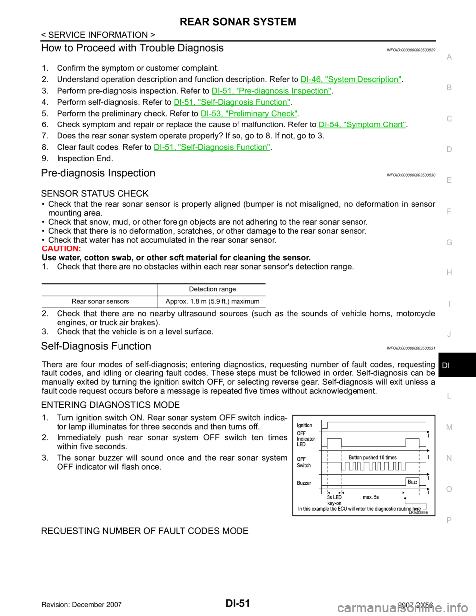
ENTERING DIAGNOSTICS MODE
1. Turn ignition switch ON. Rear sonar system OFF switch indica-
tor lamp illuminates for three seconds and then turns off.
2. Immediately push rear sonar system OFF switch ten times
within five seconds.
3. The sonar buzzer will sound once and the rear sonar system
OFF indicator will flash once.
REQUESTING NUMBER OF FAULT CODES MODE
Detection range
Rear sonar sensors Approx. 1.8 m (5.9 ft.) maximum
LKIA0389E
Page 1063 of 3061
DI-52
< SERVICE INFORMATION >
REAR SONAR SYSTEM
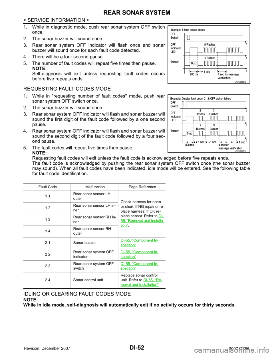
1. While in diagnostic mode, push rear sonar system OFF switch
once.
2. The sonar buzzer will sound once.
3. Rear sonar system OFF indicator will flash once and sonar
buzzer will sound once for each fault code detected.
4. There will be a four second pause.
5. The number of fault codes will repeat five times then pause.
NOTE:
Self-diagnosis will exit unless requesting fault codes occurs
before five repeats ends.
REQUESTING FAULT CODES MODE
1. While in "requesting number of fault codes" mode, push rear
sonar system OFF switch once.
2. The sonar buzzer will sound once.
3. Rear sonar system OFF indicator will flash and sonar buzzer will
sound the first digit of the fault code followed by a one second
pause.
4. Rear sonar system OFF indicator will flash and sonar buzzer will
sound the second digit of the fault code followed by a four sec-
ond pause.
5. The fault codes will repeat five times then pause.
NOTE:
Requesting fault codes will exit unless the fault code is acknowledged before five repeats ends.
The fault code is acknowledged by pushing the rear sonar system OFF switch once (the sonar buzzer
may sound). When all fault codes have been indicated, idle mode will be entered. See the following table
for fault code identification.
IDLING OR CLEARING FAULT CODES MODE
NOTE:
While in idle mode, self-diagnosis will automatically exit if no activity occurs for thirty seconds.
LKIA0388E
Fault Code Malfunction Page Reference
1 1Rear sonar sensor LH
outer
Check harness for open
or short. If NG repair or re-
place harness. If OK re-
place sensor. Refer to DI-
55, "Removal and Installa-
tion". 1 2Rear sonar sensor LH in-
ner
1 3Rear sonar sensor RH in-
ner
1 4Rear sonar sensor RH
outer
2 1 Sonar buzzerDI-55, "
Component In-
spection"
2 2Rear sonar system OFF
indicatorDI-55, "Component In-
spection"
2 3Rear sonar system OFF
switchDI-55, "Component In-
spection"
2 4 Sonar control unitReplace sonar control
unit. Refer to DI-55, "Re-
moval and Installation".
LKIA0390E
Page 1065 of 3061
DI-54
< SERVICE INFORMATION >
REAR SONAR SYSTEM
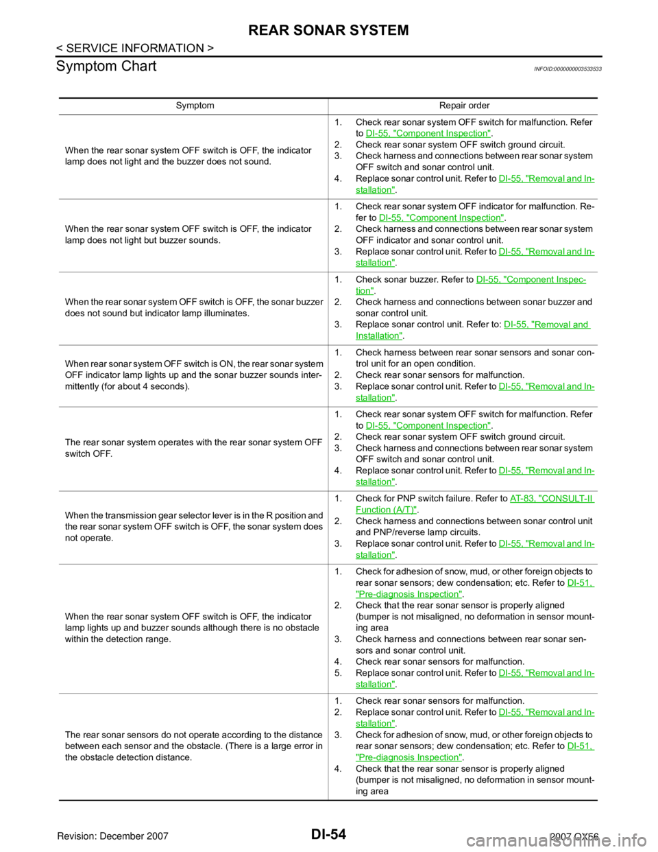
Symptom Chart
INFOID:0000000003533533
Symptom Repair order
When the rear sonar system OFF switch is OFF, the indicator
lamp does not light and the buzzer does not sound.1. Check rear sonar system OFF switch for malfunction. Refer
to DI-55, "
Component Inspection".
2. Check rear sonar system OFF switch ground circuit.
3. Check harness and connections between rear sonar system
OFF switch and sonar control unit.
4. Replace sonar control unit. Refer to DI-55, "
Removal and In-
stallation".
When the rear sonar system OFF switch is OFF, the indicator
lamp does not light but buzzer sounds.1. Check rear sonar system OFF indicator for malfunction. Re-
fer to DI-55, "
Component Inspection".
2. Check harness and connections between rear sonar system
OFF indicator and sonar control unit.
3. Replace sonar control unit. Refer to DI-55, "
Removal and In-
stallation".
When the rear sonar system OFF switch is OFF, the sonar buzzer
does not sound but indicator lamp illuminates.1. Check sonar buzzer. Refer to DI-55, "
Component Inspec-
tion".
2. Check harness and connections between sonar buzzer and
sonar control unit.
3. Replace sonar control unit. Refer to: DI-55, "
Removal and
Installation".
When rear sonar system OFF switch is ON, the rear sonar system
OFF indicator lamp lights up and the sonar buzzer sounds inter-
mittently (for about 4 seconds).1. Check harness between rear sonar sensors and sonar con-
trol unit for an open condition.
2. Check rear sonar sensors for malfunction.
3. Replace sonar control unit. Refer to DI-55, "
Removal and In-
stallation".
The rear sonar system operates with the rear sonar system OFF
switch OFF.1. Check rear sonar system OFF switch for malfunction. Refer
to DI-55, "
Component Inspection".
2. Check rear sonar system OFF switch ground circuit.
3. Check harness and connections between rear sonar system
OFF switch and sonar control unit.
4. Replace sonar control unit. Refer to DI-55, "
Removal and In-
stallation".
When the transmission gear selector lever is in the R position and
the rear sonar system OFF switch is OFF, the sonar system does
not operate.1. Check for PNP switch failure. Refer to AT- 8 3 , "
CONSULT-II
Function (A/T)".
2. Check harness and connections between sonar control unit
and PNP/reverse lamp circuits.
3. Replace sonar control unit. Refer to DI-55, "
Removal and In-
stallation".
When the rear sonar system OFF switch is OFF, the indicator
lamp lights up and buzzer sounds although there is no obstacle
within the detection range.1. Check for adhesion of snow, mud, or other foreign objects to
rear sonar sensors; dew condensation; etc. Refer to DI-51,
"Pre-diagnosis Inspection".
2. Check that the rear sonar sensor is properly aligned
(bumper is not misaligned, no deformation in sensor mount-
ing area
3. Check harness and connections between rear sonar sen-
sors and sonar control unit.
4. Check rear sonar sensors for malfunction.
5. Replace sonar control unit. Refer to DI-55, "
Removal and In-
stallation".
The rear sonar sensors do not operate according to the distance
between each sensor and the obstacle. (There is a large error in
the obstacle detection distance.1. Check rear sonar sensors for malfunction.
2. Replace sonar control unit. Refer to DI-55, "
Removal and In-
stallation".
3. Check for adhesion of snow, mud, or other foreign objects to
rear sonar sensors; dew condensation; etc. Refer to DI-51,
"Pre-diagnosis Inspection".
4. Check that the rear sonar sensor is properly aligned
(bumper is not misaligned, no deformation in sensor mount-
ing area
Page 1066 of 3061
REAR SONAR SYSTEM
DI-55
< SERVICE INFORMATION >
C
D
E
F
G
H
I
J
L
MA
B
DI
N
O
P
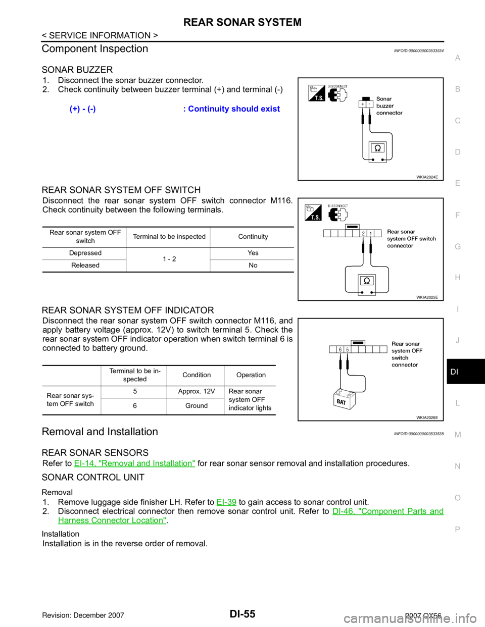
Component InspectionINFOID:0000000003533534
SONAR BUZZER
1. Disconnect the sonar buzzer connector.
2. Check continuity between buzzer terminal (+) and terminal (-)
REAR SONAR SYSTEM OFF SWITCH
Disconnect the rear sonar system OFF switch connector M116.
Check continuity between the following terminals.
REAR SONAR SYSTEM OFF INDICATOR
Disconnect the rear sonar system OFF switch connector M116, and
apply battery voltage (approx. 12V) to switch terminal 5. Check the
rear sonar system OFF indicator operation when switch terminal 6 is
connected to battery ground.
Removal and InstallationINFOID:0000000003533535
REAR SONAR SENSORS
Refer to EI-14, "Removal and Installation" for rear sonar sensor removal and installation procedures.
SONAR CONTROL UNIT
Removal
1. Remove luggage side finisher LH. Refer to EI-39 to gain access to sonar control unit.
2. Disconnect electrical connector then remove sonar control unit. Refer to DI-46, "
Component Parts and
Harness Connector Location".
Installation
Installation is in the reverse order of removal.(+) - (-) : Continuity should exist
WKIA2024E
Rear sonar system OFF
switch Terminal to be inspected Continuity
Depressed
1 - 2Ye s
Released No
WKIA2025E
Terminal to be in-
spectedCondition Operation
Rear sonar sys-
tem OFF switch5 Approx. 12V Rear sonar
system OFF
indicator lights 6Ground
WKIA2026E
Page 1084 of 3061
EC-1
ENGINE
C
D
E
F
G
H
I
J
K
L
M
SECTION EC
A
EC
N
O
P
CONTENTS
ENGINE CONTROL SYSTEM
SERVICE INFORMATION ............................9
INDEX FOR DTC .................................................9
DTC No. Index ..........................................................9
Alphabetical Index ...................................................12
PRECAUTIONS ..................................................17
Precaution for Supplemental Restraint System
(SRS) "AIR BAG" and "SEAT BELT PRE-TEN-
SIONER" .................................................................
17
On Board Diagnosis (OBD) System of Engine and
A/T ...........................................................................
17
Precaution ...............................................................17
PREPARATION ..................................................21
Special Service Tool ...............................................21
Commercial Service Tool ........................................22
ENGINE CONTROL SYSTEM ............................24
Schematic ...............................................................24
Multiport Fuel Injection (MFI) System .....................24
Electronic Ignition (EI) System ................................27
Fuel Cut Control (at No Load and High Engine
Speed) .....................................................................
27
AIR CONDITIONING CUT CONTROL ...............29
Input/Output Signal Chart ........................................29
System Description .................................................29
AUTOMATIC SPEED CONTROL DEVICE
(ASCD) ...............................................................
30
System Description .................................................30
Component Description ...........................................31
CAN COMMUNICATION ....................................32
System Description .................................................32
EVAPORATIVE EMISSION SYSTEM ................33
Description ..............................................................33
Component Inspection ............................................35
Removal and Installation .........................................37
How to Detect Fuel Vapor Leakage ........................37
ON BOARD REFUELING VAPOR RECOV-
ERY (ORVR) ......................................................
40
System Description ..................................................40
Diagnosis Procedure ...............................................40
Component Inspection .............................................42
POSITIVE CRANKCASE VENTILATION .........45
Description ...............................................................45
Component Inspection .............................................45
IVIS (INFINITI VEHICLE IMMOBILIZER SYS-
TEM-NATS) .......................................................
47
Description ...............................................................47
ON BOARD DIAGNOSTIC (OBD) SYSTEM ....48
Introduction ..............................................................48
Two Trip Detection Logic .........................................48
Emission-related Diagnostic Information .................49
Malfunction Indicator Lamp (MIL) ............................63
OBD System Operation Chart .................................65
BASIC SERVICE PROCEDURE .......................71
Basic Inspection ......................................................71
Idle Speed and Ignition Timing Check .....................75
Procedure After Replacing ECM .............................77
VIN Registration ......................................................77
Accelerator Pedal Released Position Learning .......77
Throttle Valve Closed Position Learning .................77
Idle Air Volume Learning .........................................78
Fuel Pressure Check ...............................................80
TROUBLE DIAGNOSIS ....................................82
Trouble Diagnosis Introduction ................................82
DTC Inspection Priority Chart ..................................87
Fail-Safe Chart ........................................................88
Symptom Matrix Chart .............................................90
Engine Control Component Parts Location .............94
Vacuum Hose Drawing ..........................................100
Circuit Diagram ......................................................101
ECM Harness Connector Terminal Layout ............103
ECM Terminal and Reference Value .....................103
Page 1091 of 3061

EC-8
DTC Confirmation Procedure ................................567
Wiring Diagram ......................................................569
Diagnosis Procedure .............................................570
Component Inspection ...........................................572
Removal and Installation .......................................573
DTC P2135 TP SENSOR .................................574
Component Description .........................................574
CONSULT-II Reference Value in Data Monitor
Mode ......................................................................
574
On Board Diagnosis Logic .....................................574
DTC Confirmation Procedure ................................574
Wiring Diagram ......................................................576
Diagnosis Procedure .............................................577
Component Inspection ...........................................579
Removal and Installation .......................................580
DTC P2138 APP SENSOR ..............................581
Component Description .........................................581
CONSULT-II Reference Value in Data Monitor
Mode ......................................................................
581
On Board Diagnosis Logic .....................................581
DTC Confirmation Procedure ................................582
Wiring Diagram ......................................................583
Diagnosis Procedure .............................................584
Component Inspection ...........................................587
Removal and Installation .......................................587
DTC P2A00, P2A03 A/F SENSOR 1 ...............588
Component Description .........................................588
CONSULT-II Reference Value in Data Monitor
Mode ......................................................................
588
On Board Diagnosis Logic .....................................588
DTC Confirmation Procedure ................................588
Wiring Diagram ......................................................590
Diagnosis Procedure .............................................593
Removal and Installation .......................................596
ASCD BRAKE SWITCH ..................................597
Component Description .........................................597
CONSULT-II Reference Value in Data Monitor
Mode ......................................................................
597
Wiring Diagram ......................................................598
Diagnosis Procedure .............................................599
Component Inspection ...........................................602
ASCD INDICATOR ..........................................603
Component Description .........................................603
CONSULT-II Reference Value in Data Monitor
Mode ......................................................................
603
Wiring Diagram ......................................................604
Diagnosis Procedure .............................................604
ELECTRICAL LOAD SIGNAL .........................606
Description .............................................................606
CONSULT-II Reference Value in Data Monitor
Mode ......................................................................
606
Diagnosis Procedure .............................................606
FUEL INJECTOR ..............................................608
Component Description ........................................608
CONSULT-II Reference Value in Data Monitor
Mode .....................................................................
608
Wiring Diagram .....................................................609
Diagnosis Procedure .............................................610
Component Inspection ..........................................612
Removal and Installation .......................................612
FUEL PUMP .....................................................613
Description ............................................................613
CONSULT-II Reference Value in Data Monitor
Mode .....................................................................
613
Wiring Diagram .....................................................614
Diagnosis Procedure .............................................615
Component Inspection ..........................................617
Removal and Installation .......................................618
ICC BRAKE SWITCH .......................................619
Component Description ........................................619
CONSULT-II Reference Value in Data Monitor
Mode .....................................................................
619
Wiring Diagram .....................................................620
Diagnosis Procedure .............................................621
Component Inspection ..........................................624
IGNITION SIGNAL ............................................626
Component Description ........................................626
Wiring Diagram .....................................................627
Diagnosis Procedure .............................................632
Component Inspection ..........................................635
Removal and Installation .......................................637
REFRIGERANT PRESSURE SENSOR ...........638
Component Description ........................................638
Wiring Diagram .....................................................639
Diagnosis Procedure .............................................640
Removal and Installation .......................................642
MIL AND DATA LINK CONNECTOR ...............643
Wiring Diagram .....................................................643
SERVICE DATA AND SPECIFICATIONS
(SDS) ................................................................
645
Fuel Pressure ........................................................645
Idle Speed and Ignition Timing .............................645
Calculated Load Value ..........................................645
Mass Air Flow Sensor ...........................................645
Intake Air Temperature Sensor .............................645
Engine Coolant Temperature Sensor ...................645
A/F Sensor 1 Heater .............................................645
Heated Oxygen sensor 2 Heater ..........................645
Crankshaft Position Sensor (POS) .......................646
Camshaft Position Sensor (PHASE) .....................646
Throttle Control Motor ...........................................646
Fuel Injector ..........................................................646
Fuel Pump .............................................................646