Page 1154 of 3061
BASIC SERVICE PROCEDURE
EC-71
< SERVICE INFORMATION >
C
D
E
F
G
H
I
J
K
L
MA
EC
N
P O
BASIC SERVICE PROCEDURE
Basic InspectionINFOID:0000000003531609
1.INSPECTION START
1. Check service records for any recent repairs that may indicate a related malfunction, or a current need for
scheduled maintenance.
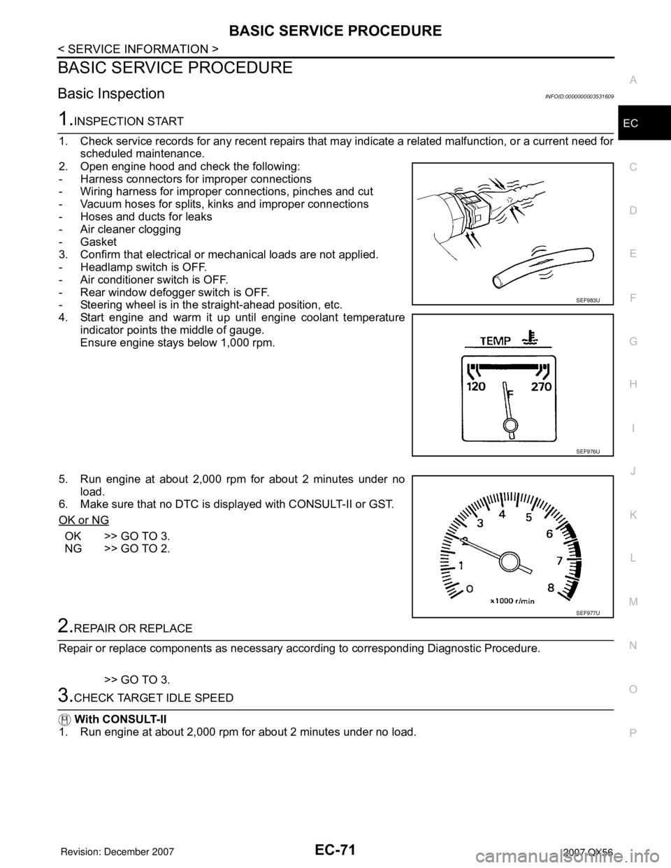
2. Open engine hood and check the following:
- Harness connectors for improper connections
- Wiring harness for improper connections, pinches and cut
- Vacuum hoses for splits, kinks and improper connections
- Hoses and ducts for leaks
- Air cleaner clogging
- Gasket
3. Confirm that electrical or mechanical loads are not applied.
- Headlamp switch is OFF.
- Air conditioner switch is OFF.
- Rear window defogger switch is OFF.
- Steering wheel is in the straight-ahead position, etc.
4. Start engine and warm it up until engine coolant temperature
indicator points the middle of gauge.
Ensure engine stays below 1,000 rpm.
5. Run engine at about 2,000 rpm for about 2 minutes under no
load.
6. Make sure that no DTC is displayed with CONSULT-II or GST.
OK or NG
OK >> GO TO 3.
NG >> GO TO 2.
2.REPAIR OR REPLACE
Repair or replace components as necessary according to corresponding Diagnostic Procedure.
>> GO TO 3.
3.CHECK TARGET IDLE SPEED
With CONSULT-II
1. Run engine at about 2,000 rpm for about 2 minutes under no load.
SEF983U
SEF976U
SEF977U
Page 1445 of 3061
EC-362
< SERVICE INFORMATION >
DTC P0442 EVAP CONTROL SYSTEM
6.CHECK FOR EVAP LEAK
With CONSULT-II
1. Turn ignition switch ON.
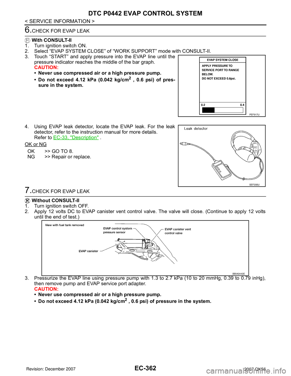
2. Select “EVAP SYSTEM CLOSE” of “WORK SUPPORT” mode with CONSULT-II.
3. Touch “START” and apply pressure into the EVAP line until the
pressure indicator reaches the middle of the bar graph.
CAUTION:
• Never use compressed air or a high pressure pump.
• Do not exceed 4.12 kPa (0.042 kg/cm
2 , 0.6 psi) of pres-
sure in the system.
4. Using EVAP leak detector, locate the EVAP leak. For the leak
detector, refer to the instruction manual for more details.
Refer to EC-33, "
Description" .
OK or NG
OK >> GO TO 8.
NG >> Repair or replace.
7.CHECK FOR EVAP LEAK
Without CONSULT-II
1. Turn ignition switch OFF.
2. Apply 12 volts DC to EVAP canister vent control valve. The valve will close. (Continue to apply 12 volts
until the end of test.)
3. Pressurize the EVAP line using pressure pump with 1.3 to 2.7 kPa (10 to 20 mmHg, 0.39 to 0.79 inHg),
then remove pump and EVAP service port adapter.
CAUTION:
• Never use compressed air or a high pressure pump.
• Do not exceed 4.12 kPa (0.042 kg/cm
2 , 0.6 psi) of pressure in the system.
PEF917U
SEF200U
BBIA0443E
Page 1494 of 3061
DTC P0455 EVAP CONTROL SYSTEM
EC-411
< SERVICE INFORMATION >
C
D
E
F
G
H
I
J
K
L
MA
EC
N
P O
8.INSTALL THE PRESSURE PUMP
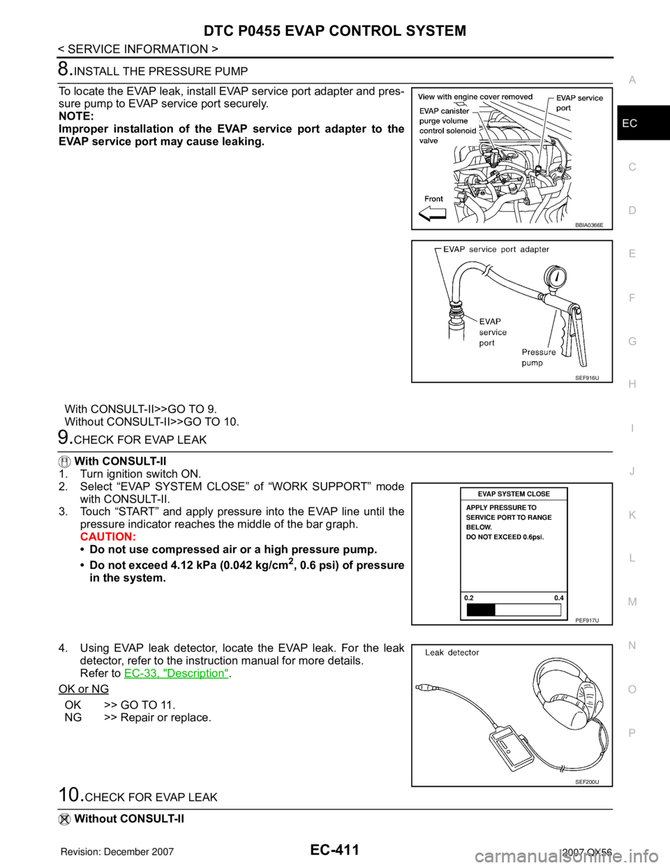
To locate the EVAP leak, install EVAP service port adapter and pres-
sure pump to EVAP service port securely.
NOTE:
Improper installation of the EVAP service port adapter to the
EVAP service port may cause leaking.
With CONSULT-II>>GO TO 9.
Without CONSULT-II>>GO TO 10.
9.CHECK FOR EVAP LEAK
With CONSULT-II
1. Turn ignition switch ON.
2. Select “EVAP SYSTEM CLOSE” of “WORK SUPPORT” mode
with CONSULT-II.
3. Touch “START” and apply pressure into the EVAP line until the
pressure indicator reaches the middle of the bar graph.
CAUTION:
• Do not use compressed air or a high pressure pump.
• Do not exceed 4.12 kPa (0.042 kg/cm
2, 0.6 psi) of pressure
in the system.
4. Using EVAP leak detector, locate the EVAP leak. For the leak
detector, refer to the instruction manual for more details.
Refer to EC-33, "
Description".
OK or NG
OK >> GO TO 11.
NG >> Repair or replace.
10.CHECK FOR EVAP LEAK
Without CONSULT-II
BBIA0366E
SEF916U
PEF917U
SEF200U
Page 1501 of 3061
EC-418
< SERVICE INFORMATION >
DTC P0456 EVAP CONTROL SYSTEM
3.CHECK FUEL FILLER CAP FUNCTION
Check for air releasing sound while opening the fuel filler cap.
OK or NG
OK >> GO TO 5.
NG >> GO TO 4.
4.CHECK FUEL TANK VACUUM RELIEF VALVE
Refer to EC-35, "
Component Inspection" .
OK or NG
OK >> GO TO 5.
NG >> Replace fuel filler cap with a genuine one.
5.INSTALL THE PRESSURE PUMP
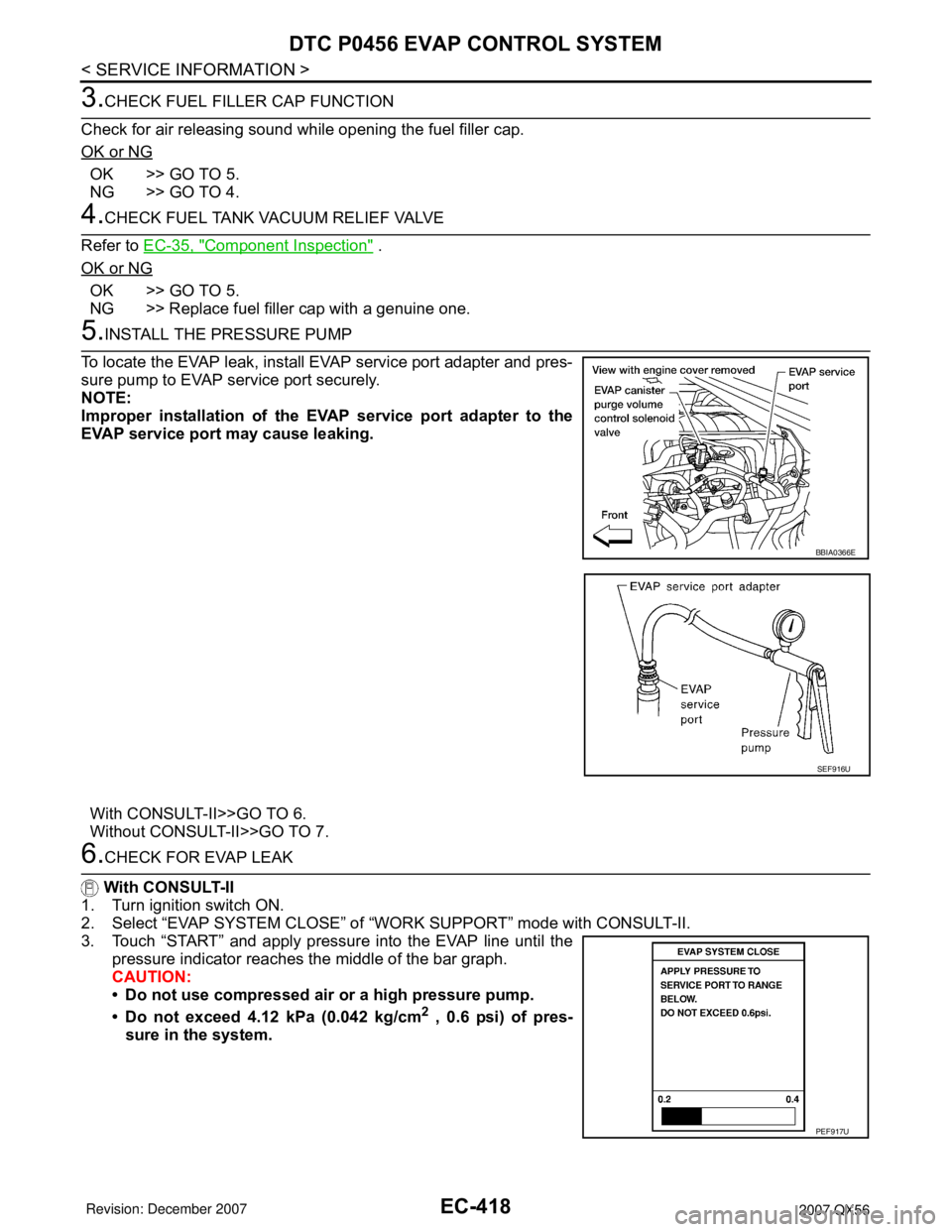
To locate the EVAP leak, install EVAP service port adapter and pres-
sure pump to EVAP service port securely.
NOTE:
Improper installation of the EVAP service port adapter to the
EVAP service port may cause leaking.
With CONSULT-II>>GO TO 6.
Without CONSULT-II>>GO TO 7.
6.CHECK FOR EVAP LEAK
With CONSULT-II
1. Turn ignition switch ON.
2. Select “EVAP SYSTEM CLOSE” of “WORK SUPPORT” mode with CONSULT-II.
3. Touch “START” and apply pressure into the EVAP line until the
pressure indicator reaches the middle of the bar graph.
CAUTION:
• Do not use compressed air or a high pressure pump.
• Do not exceed 4.12 kPa (0.042 kg/cm
2 , 0.6 psi) of pres-
sure in the system.
BBIA0366E
SEF916U
PEF917U
Page 1612 of 3061
DTC P1572 ASCD BRAKE SWITCH
EC-529
< SERVICE INFORMATION >
C
D
E
F
G
H
I
J
K
L
MA
EC
N
P O
TESTING CONDITION:
Steps 4 and 5 may be conducted with the drive wheels lifted in the shop or by driving the vehicle. If a
road test is expected to be easier, it is unnecessary to lift the vehicle.
WITH CONSULT-II
1. Start engine (VDC switch OFF).
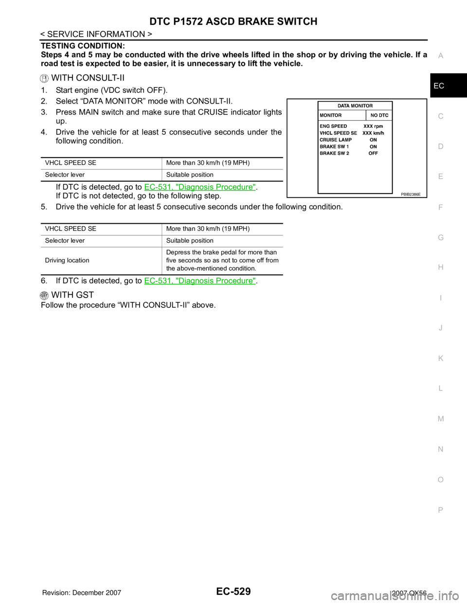
2. Select “DATA MONITOR” mode with CONSULT-II.
3. Press MAIN switch and make sure that CRUISE indicator lights
up.
4. Drive the vehicle for at least 5 consecutive seconds under the
following condition.
If DTC is detected, go to EC-531, "
Diagnosis Procedure".
If DTC is not detected, go to the following step.
5. Drive the vehicle for at least 5 consecutive seconds under the following condition.
6. If DTC is detected, go to EC-531, "
Diagnosis Procedure".
WITH GST
Follow the procedure “WITH CONSULT-II” above.
VHCL SPEED SE More than 30 km/h (19 MPH)
Selector lever Suitable position
VHCL SPEED SE More than 30 km/h (19 MPH)
Selector lever Suitable position
Driving locationDepress the brake pedal for more than
five seconds so as not to come off from
the above-mentioned condition.
PBIB2386E
Page 1686 of 3061

ASCD INDICATOR
EC-603
< SERVICE INFORMATION >
C
D
E
F
G
H
I
J
K
L
MA
EC
N
P O
ASCD INDICATOR
Component DescriptionINFOID:0000000003532153
ASCD indicator lamp illuminates to indicate ASCD operation status. Lamp has two indicators, CRUISE and
SET, and is integrated in combination meter.
CRUISE indicator illuminates when MAIN switch on ASCD steering switch is turned ON to indicate that ASCD
system is ready for operation.
SET indicator illuminates when following conditions are met.
• CRUISE indicator is illuminated.
• SET/COAST switch on ASCD steering switch is turned ON while vehicle speed is within the range of ASCD
setting.
SET indicator remains lit during ASCD control.
Refer to EC-30
for the ASCD function.
CONSULT-II Reference Value in Data Monitor ModeINFOID:0000000003532154
Specification data are reference value.
MONITOR ITEM CONDITION SPECIFICATION
CRUISE LAMP • Ignition switch: ON• MAIN switch: Pressed at the 1st
time → at the 2nd timeON → OFF
SET LAMP• MAIN switch: ON
• When vehicle speed is be-
tween 40 km/h (25 MPH) and
144 km/h (89 MPH)• ASCD: Operating ON
• ASCD: Not operating OFF
Page 1687 of 3061
EC-604
< SERVICE INFORMATION >
ASCD INDICATOR
Wiring Diagram
INFOID:0000000003532155
Diagnosis ProcedureINFOID:0000000003532156
1.CHECK OVERALL FUNCTION
Check ASCD indicator under the following conditions.
BBWA2109E
Page 1688 of 3061
ASCD INDICATOR
EC-605
< SERVICE INFORMATION >
C
D
E
F
G
H
I
J
K
L
MA
EC
N
P O
OK or NG
OK >>INSPECTION END
NG >> GO TO 2.
2.CHECK DTC
Check that DTC U1000 or U1001 is not displayed.
OK or NG
OK >> GO TO 3.
NG >> Perform trouble diagnosis for DTC U1000, U1001. Refer to EC-145
.
3.CHECK COMBINATION METER FUNCTION
Refer to DI-5
.
OK or NG
OK >> GO TO 4.
NG >> Go to DI-5
.
4.CHECK INTERMITTENT INCIDENT
Refer to EC-138
.
>>INSPECTION END
ASCD INDICATOR CONDITION SPECIFICATION
CRUISE LAMP • Ignition switch: ON• MAIN switch: Pressed at the 1st
time → at the 2nd timeON → OFF
SET LAMP• MAIN switch: ON
• When vehicle speed is between
40 km/h (25 MPH) and 144 km/h
(89 MPH)•ASCD: Operating ON
• ASCD: Not operating OFF