2007 INFINITI QX56 service indicator
[x] Cancel search: service indicatorPage 2213 of 3061

LT-6
< SERVICE INFORMATION >
HEADLAMP (FOR USA)
• to BCM terminal 38.
Ground is supplied
• to BCM terminal 67
• through grounds M57, M61 and M79, and
• to IPDM E/R terminals 38 and 59
• through grounds E9, E15 and E24.
Low Beam Operation
With the lighting switch in 2ND position, the BCM receives input requesting the headlamps to illuminate. This
input is communicated to the IPDM E/R across the CAN communication lines. The CPU of the IPDM E/R con-
trols the headlamp low relay coil. When energized, this relay directs power
• through 15A fuse (No. 41, located in the IPDM E/R)
• through IPDM E/R terminal 54
• to front combination lamp RH terminal 5, and
• through 15A fuse (No. 40, located in the IPDM E/R)
• through IPDM E/R terminal 52
• to front combination lamp LH terminal 5.
Ground is supplied
• to front combination lamp LH and RH terminal 1
• through grounds E9, E15 and E24.
With power and ground supplied, low beam headlamps illuminate.
High Beam Operation/Flash-to-Pass Operation
With the lighting switch in 2ND position and placed in HIGH or PASS position, the BCM receives input request-
ing the headlamp high beams to illuminate. This input is communicated to the IPDM E/R across the CAN com-
munication lines. The CPU of the combination meter controls the ON/OFF status of the HIGH BEAM indicator.
The CPU of the IPDM E/R controls the headlamp high relay coil. When energized, this relay directs power
• through 10A fuse (No. 34, located in the IPDM E/R)
• through IPDM E/R terminal 56
• to front combination lamp RH terminal 6, and
• through 10A fuse (No. 35, located in the IPDM E/R)
• through IPDM E/R terminal 55
• to front combination lamp LH terminal 6.
Ground is supplied
• to front combination lamp LH and RH terminal 2
• through grounds E9, E15 and E24.
With power and ground supplied, the high beam headlamps illuminate.
XENON HEADLAMP
Xenon type headlamp is adopted to the low beam headlamps. Xenon bulbs do not use a filament. Instead,
they produce light when a high voltage current is passed between two tungsten electrodes through a mixture
of xenon (an inert gas) and certain other metal halides. In addition to added lighting power, electronic control
of the power supply gives the headlamps stable quality and tone color.
Following are some of the many advantages of the xenon type headlamp.
• The light produced by the headlamps is a white color comparable to sunlight that is easy on the eyes.
• Light output is nearly double that of halogen headlamps, affording increased area of illumination.
• The light features a high relative spectral distribution at wavelengths to which the human eye is most sensi-
tive. This means that even in the rain, more light is reflected back from the road surface toward the vehicle,
for added visibility.
• Power consumption is approximately 25 percent less than halogen headlamps, reducing battery load.
BATTERY SAVER CONTROL
When the combination switch (lighting switch) is in the 2ND position (ON), and the ignition switch is turned
from ON or ACC to OFF, the battery saver control feature is activated.
Under this condition, the headlamps remain illuminated for 5 minutes, unless the combination switch (lighting
switch) position is changed. If the combination switch (lighting switch) position is changed, then the headlamps
are turned off.
AUTO LIGHT OPERATION
Refer to LT-34, "System Description" for auto light operation.
VEHICLE SECURITY SYSTEM (PANIC ALARM)
Page 2223 of 3061
LT-16
< SERVICE INFORMATION >
HEADLAMP (FOR USA)
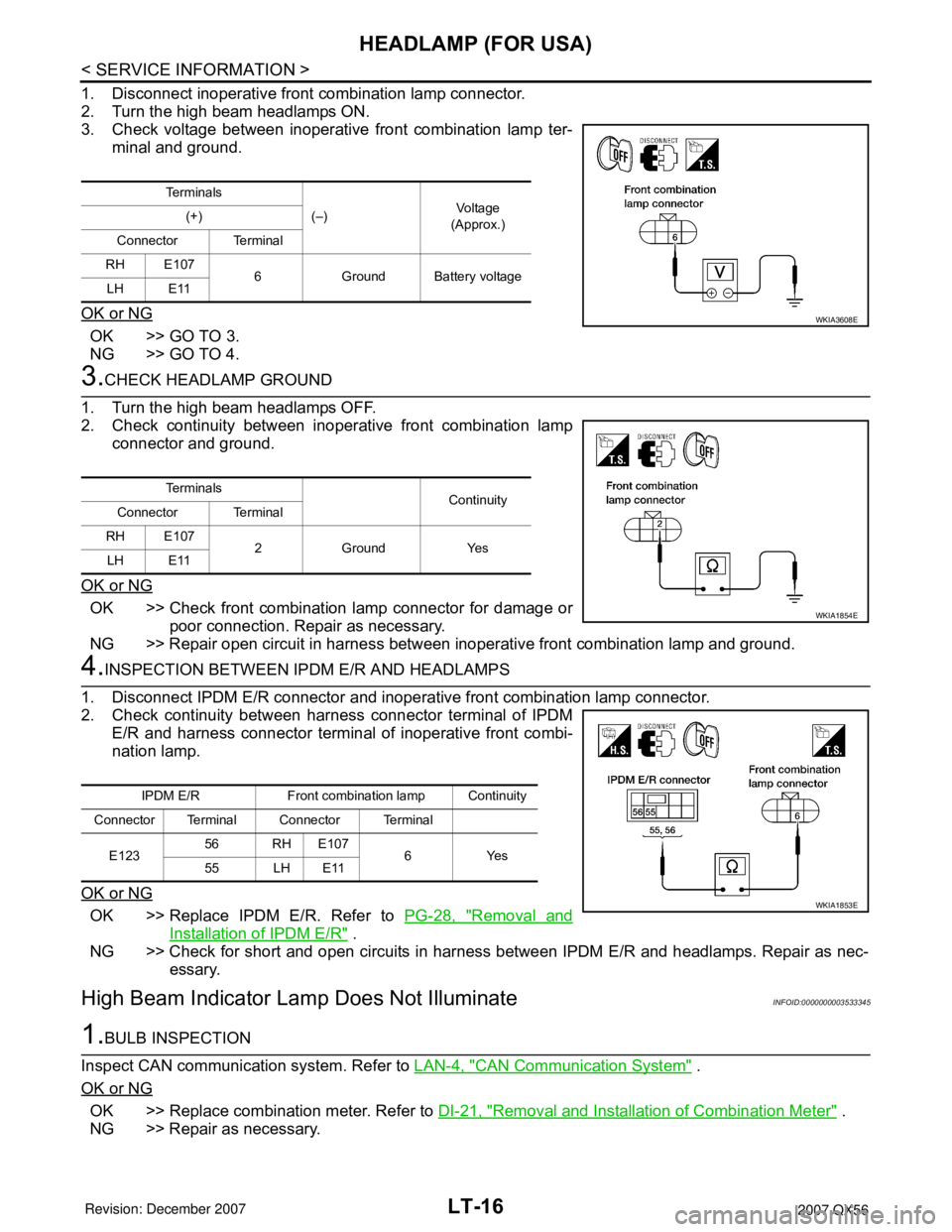
1. Disconnect inoperative front combination lamp connector.
2. Turn the high beam headlamps ON.
3. Check voltage between inoperative front combination lamp ter-
minal and ground.
OK or NG
OK >> GO TO 3.
NG >> GO TO 4.
3.CHECK HEADLAMP GROUND
1. Turn the high beam headlamps OFF.
2. Check continuity between inoperative front combination lamp
connector and ground.
OK or NG
OK >> Check front combination lamp connector for damage or
poor connection. Repair as necessary.
NG >> Repair open circuit in harness between inoperative front combination lamp and ground.
4.INSPECTION BETWEEN IPDM E/R AND HEADLAMPS
1. Disconnect IPDM E/R connector and inoperative front combination lamp connector.
2. Check continuity between harness connector terminal of IPDM
E/R and harness connector terminal of inoperative front combi-
nation lamp.
OK or NG
OK >> Replace IPDM E/R. Refer to PG-28, "Removal and
Installation of IPDM E/R" .
NG >> Check for short and open circuits in harness between IPDM E/R and headlamps. Repair as nec-
essary.
High Beam Indicator Lamp Does Not IlluminateINFOID:0000000003533345
1.BULB INSPECTION
Inspect CAN communication system. Refer to LAN-4, "
CAN Communication System" .
OK or NG
OK >> Replace combination meter. Refer to DI-21, "Removal and Installation of Combination Meter" .
NG >> Repair as necessary.
Te r m i n a l s
(–)Vo l ta g e
(Approx.) (+)
Connector Terminal
RH E107
6 Ground Battery voltage
LH E11
WKIA3608E
Te r m i n a l s
Continuity
Connector Terminal
RH E107
2 Ground Yes
LH E11
WKIA1854E
IPDM E/R Front combination lamp Continuity
Connector Terminal Connector Terminal
E12356 RH E107
6Yes
55 LH E11
WKIA1853E
Page 2238 of 3061
HEADLAMP (FOR CANADA) - DAYTIME LIGHT SYSTEM -
LT-31
< SERVICE INFORMATION >
C
D
E
F
G
H
I
J
L
MA
B
LT
N
O
P
3. Perform the Preliminary Check. Refer to LT-31, "Preliminary Check" .
4. Check symptom and repair or replace the cause of malfunction.
5. Does the headlamp operate normally? If YES: GO TO 6. If NO: GO TO 4.
6. Inspection End.
Preliminary CheckINFOID:0000000003533360
CHECK BCM CONFIGURATION
1.CHECK BCM CONFIGURATION
Confirm BCM configuration for "DTRL" is set to "WITH". Refer to BCS-18, "
Configuration" .
OK or NG
OK >> Continue preliminary check. Refer to BCS-15, "BCM Power Supply and Ground Circuit Inspec-
tion" .
NG >> Change BCM configuration for "DTRL" to "WITH". Refer to BCS-18, "
Configuration" .
INSPECT POWER SUPPLY AND GROUND CIRCUIT FOR BCM
Refer to BCS-15, "BCM Power Supply and Ground Circuit Inspection".
INSPECTION PARKING BRAKE SWITCH CIRCUIT
1.CHECK BRAKE INDICATOR
1. Turn ignition switch ON.
2. Apply parking brake.
3. Release parking brake.
OK or NG
OK >> Inspection End.
NG >> GO TO 2.
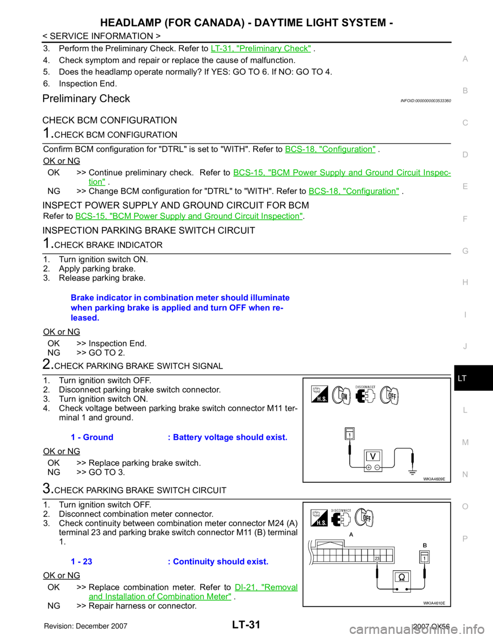
2.CHECK PARKING BRAKE SWITCH SIGNAL
1. Turn ignition switch OFF.
2. Disconnect parking brake switch connector.
3. Turn ignition switch ON.
4. Check voltage between parking brake switch connector M11 ter-
minal 1 and ground.
OK or NG
OK >> Replace parking brake switch.
NG >> GO TO 3.
3.CHECK PARKING BRAKE SWITCH CIRCUIT
1. Turn ignition switch OFF.
2. Disconnect combination meter connector.
3. Check continuity between combination meter connector M24 (A)
terminal 23 and parking brake switch connector M11 (B) terminal
1.
OK or NG
OK >> Replace combination meter. Refer to DI-21, "Removal
and Installation of Combination Meter" .
NG >> Repair harness or connector.Brake indicator in combination meter should illuminate
when parking brake is applied and turn OFF when re-
leased.
1 - Ground : Battery voltage should exist.
WKIA4609E
1 - 23 : Continuity should exist.
WKIA4610E
Page 2265 of 3061

LT-58
< SERVICE INFORMATION >
TURN SIGNAL AND HAZARD WARNING LAMPS
• to rear combination lamp LH terminal 4
• through rear combination signal lamp LH terminal 6
• to grounds B7 and B19.
BCM sends signal to combination meter through CAN communication lines, and turns on turn signal indicator
lamp within combination meter.
RH Turn
When the turn signal switch is moved to the right position, the BCM, interpreting it as turn signal is ON, outputs
turn signal from BCM terminal 61.
The BCM supplies power
• through BCM terminal 61
• to front turn/fog lamp RH terminal 2
• through front turn/fog lamp RH terminal 3
• to grounds E9, E15 and E24,
• to door mirror RH terminal 15
• through door mirror RH terminal 11
• to grounds M57, M61 and M79 and
• to rear combination lamp RH terminal 4
• through rear combination lamp terminal 6
• to grounds B117 and B132.
BCM sends signal to combination meter through CAN communication lines, and turns on turn signal indicator
lamp within combination meter.
HAZARD LAMP OPERATION
Power is supplied at all times
• through 50A fusible link (letter f , located in the fuse and fusible link box)
• to BCM terminal 70, and
• through 10A fuse [No. 19, located in the fuse block (J/B)]
• to combination meter terminal 8.
Ground is supplied
• to BCM terminal 67 and
• to combination meter terminal 17
• through grounds M57, M61 and M79.
When the hazard switch is depressed, ground is supplied
• to BCM terminal 29
• through hazard switch terminal 2
• through hazard switch terminal 1
• through grounds M57, M61 and M79.
When the hazard switch is depressed, the BCM, interpreting it as hazard warning lamps are ON, outputs turn
signal from BCM terminals 60 and 61.
The BCM supplies power
• through BCM terminals 60 and 61
• to front turn/fog lamp LH and RH terminal 2
• through front turn/fog lamp LH and RH terminal 3
• to grounds E9, E15 and E24,
• to door mirror LH and RH terminal 15
• through door mirror LH and RH terminal 11
• to grounds M57, M61 and M79,
• to rear turn signal lamp LH terminal 1
• through rear turn signal lamp LH terminal 3
• to grounds B7 and B19, and
• to rear turn signal lamp RH terminal 4
• through rear turn signal lamp RH terminal 6
• to grounds B117 and B132.
BCM sends signal to combination meter through CAN communication lines, and turns on turn signal indicator
lamps within combination meter.
REMOTE KEYLESS ENTRY SYSTEM OPERATION
Power is supplied at all times
• through 50A fusible link (letter f , located in the fuse and fusible link box)
• to BCM terminal 70, and
• through 10A fuse [No. 19, located in the fuse block (J/B)]
Page 2266 of 3061
TURN SIGNAL AND HAZARD WARNING LAMPS
LT-59
< SERVICE INFORMATION >
C
D
E
F
G
H
I
J
L
MA
B
LT
N
O
P
• to combination meter terminal 8.
Ground is supplied
• to BCM terminal 67 and
• to combination meter terminal 17
• through grounds M57, M61 and M79.
When the remote keyless entry system is triggered by input from the keyfob, the BCM, interpreting it as turn
signal is ON, outputs turn signal from BCM terminals 60 and 61.
The BCM supplies power
• through BCM terminals 60 and 61
• to front turn/fog lamp LH and RH terminal 2
• through front turn/fog lamp LH and RH terminal 3
• to grounds E9, E15 and E24,
• to door mirror LH and RH terminal 15
• through door mirror LH and RH terminal 11
• to grounds M57, M61 and M79,
• to rear turn signal lamp LH terminal 1
• through rear turn signal lamp LH terminal 3
• to grounds B7 and B19, and
• to rear turn signal lamp RH terminal 4
• through rear turn signal lamp RH terminal 6
• to grounds B117 and B132.
BCM sends signal to combination meter through CAN communication lines, and turns on turn signal indicator
lamps within combination meter.
With power and input supplied, the BCM controls the flashing of the hazard warning lamps when keyfob is
used to activate the remote keyless entry system.
COMBINATION SWITCH READING FUNCTION
Refer to BCS-3, "System Description".
CAN Communication System DescriptionINFOID:0000000003533405
Refer to LAN-4, "CAN Communication System".
Page 2275 of 3061
LT-68
< SERVICE INFORMATION >
TURN SIGNAL AND HAZARD WARNING LAMPS
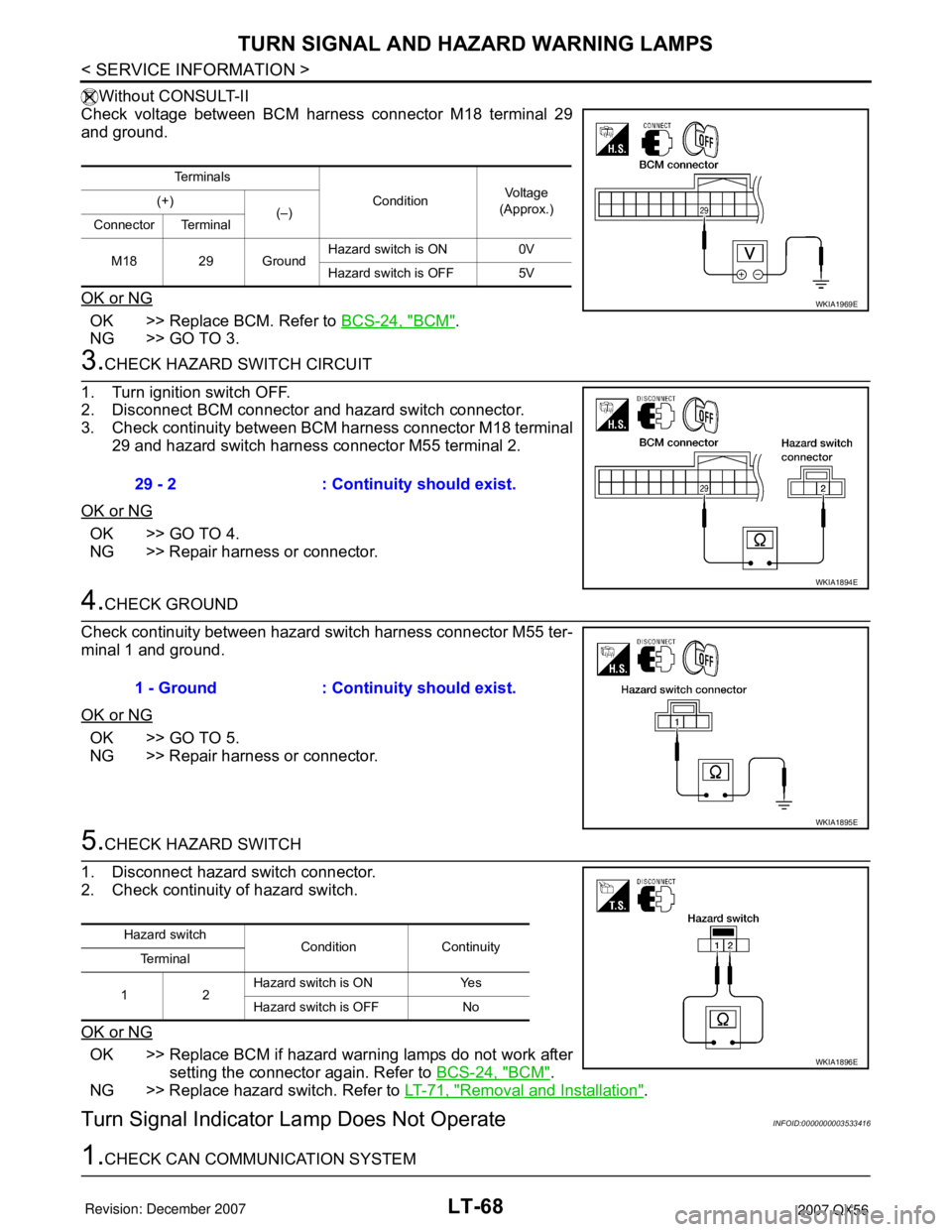
Without CONSULT-II
Check voltage between BCM harness connector M18 terminal 29
and ground.
OK or NG
OK >> Replace BCM. Refer to BCS-24, "BCM".
NG >> GO TO 3.
3.CHECK HAZARD SWITCH CIRCUIT
1. Turn ignition switch OFF.
2. Disconnect BCM connector and hazard switch connector.
3. Check continuity between BCM harness connector M18 terminal
29 and hazard switch harness connector M55 terminal 2.
OK or NG
OK >> GO TO 4.
NG >> Repair harness or connector.
4.CHECK GROUND
Check continuity between hazard switch harness connector M55 ter-
minal 1 and ground.
OK or NG
OK >> GO TO 5.
NG >> Repair harness or connector.
5.CHECK HAZARD SWITCH
1. Disconnect hazard switch connector.
2. Check continuity of hazard switch.
OK or NG
OK >> Replace BCM if hazard warning lamps do not work after
setting the connector again. Refer to BCS-24, "
BCM".
NG >> Replace hazard switch. Refer to LT-71, "
Removal and Installation".
Turn Signal Indicator Lamp Does Not OperateINFOID:0000000003533416
1.CHECK CAN COMMUNICATION SYSTEM
Te r m i n a l s
ConditionVoltag e
(Approx.) (+)
(–)
Connector Terminal
M18 29 GroundHazard switch is ON 0V
Hazard switch is OFF 5V
WKIA1969E
29 - 2 : Continuity should exist.
WKIA1894E
1 - Ground : Continuity should exist.
WKIA1895E
Hazard switch
Condition Continuity
Te r m i n a l
12Hazard switch is ON Yes
Hazard switch is OFF No
WKIA1896E
Page 2374 of 3061
MA-12
< SERVICE INFORMATION >
ENGINE MAINTENANCE
ENGINE MAINTENANCE
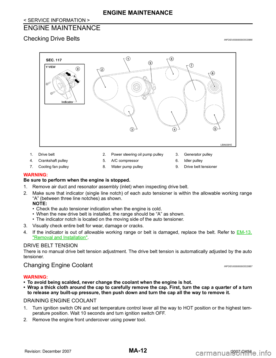
Checking Drive BeltsINFOID:0000000003533866
WARNING:
Be sure to perform when the engine is stopped.
1. Remove air duct and resonator assembly (inlet) when inspecting drive belt.
2. Make sure that indicator (single line notch) of each auto tensioner is within the allowable working range
“A” (between three line notches) as shown.
NOTE:
• Check the auto tensioner indication when the engine is cold.
• When the new drive belt is installed, the range should be “A” as shown.
• The indicator notch is located on the moving side of the auto tensioner.
3. Visually check entire belt for wear, damage or cracks.
4. If the indicator is out of allowable working range or belt is damaged, replace the belt. Refer to EM-13,
"Removal and Installation".
DRIVE BELT TENSION
There is no manual drive belt tension adjustment. The drive belt tension is automatically adjusted by the auto
tensioner.
Changing Engine CoolantINFOID:0000000003533867
WARNING:
• To avoid being scalded, never change the coolant when the engine is hot.
• Wrap a thick cloth around the cap to carefully remove the cap. First, turn the cap a quarter of a turn
to release any built-up pressure, then push down and turn the cap all the way to remove it.
DRAINING ENGINE COOLANT
1. Turn ignition switch ON and set temperature control lever all the way to HOT position or the highest tem-
perature position. Wait 10 seconds and turn ignition switch OFF.
2. Remove the engine front undercover using power tool.
1. Drive belt 2. Power steering oil pump pulley 3. Generator pulley
4. Crankshaft pulley 5. A/C compressor 6. Idler pulley
7. Cooling fan pulley 8. Water pump pulley 9. Drive belt tensioner
LBIA0391E
Page 2388 of 3061
MA-26
< SERVICE INFORMATION >
CHASSIS AND BODY MAINTENANCE
• If a tire balance machine has adhesion balance weight mode settings and drive-in weight mode setting,
select and adjust a drive-in weight mode suitable for wheels.
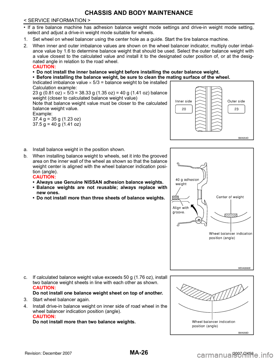
1. Set wheel on wheel balancer using the center hole as a guide. Start the tire balance machine.
2. When inner and outer imbalance values are shown on the wheel balancer indicator, multiply outer imbal-
ance value by 1.6 to determine balance weight that should be used. Select the outer balance weight with
a value closest to the calculated value and install it to the designated outer position of, or at the desig-
nated angle in relation to the road wheel.
CAUTION:
• Do not install the inner balance weight before installing the outer balance weight.
• Before installing the balance weight, be sure to clean the mating surface of the wheel.
Indicated imbalance value × 5/3 = balance weight to be installed
Calculation example:
23 g (0.81 oz) × 5/3 = 38.33 g (1.35 oz) = 40 g (1.41 oz) balance
weight (closer to calculated balance weight value)
Note that balance weight value must be closer to the calculated
balance weight value.
Example:
37.4 g = 35 g (1.23 oz)
37.5 g = 40 g (1.41 oz)
a. Install balance weight in the position shown.
b. When installing balance weight to wheels, set it into the grooved
area on the inner wall of the wheel as shown so that the balance
weight center is aligned with the wheel balancer indication posi-
tion (angle).
CAUTION:
• Always use Genuine NISSAN adhesion balance weights.
• Balance weights are not reusable; always replace with
new ones.
• Do not install more than three sheets of balance weights.
c. If calculated balance weight value exceeds 50 g (1.76 oz), install
two balance weight sheets in line with each other as shown.
CAUTION:
Do not install one balance weight sheet on top of another.
3. Start wheel balancer again.
4. Install drive-in balance weight on inner side of road wheel in the
wheel balancer indication position (angle).
CAUTION:
Do not install more than two balance weights.
SMA054D
WDIA0060E
SMA056D