2007 INFINITI QX56 service indicator
[x] Cancel search: service indicatorPage 2780 of 3061

SRS-10
< SERVICE INFORMATION >
TROUBLE DIAGNOSIS
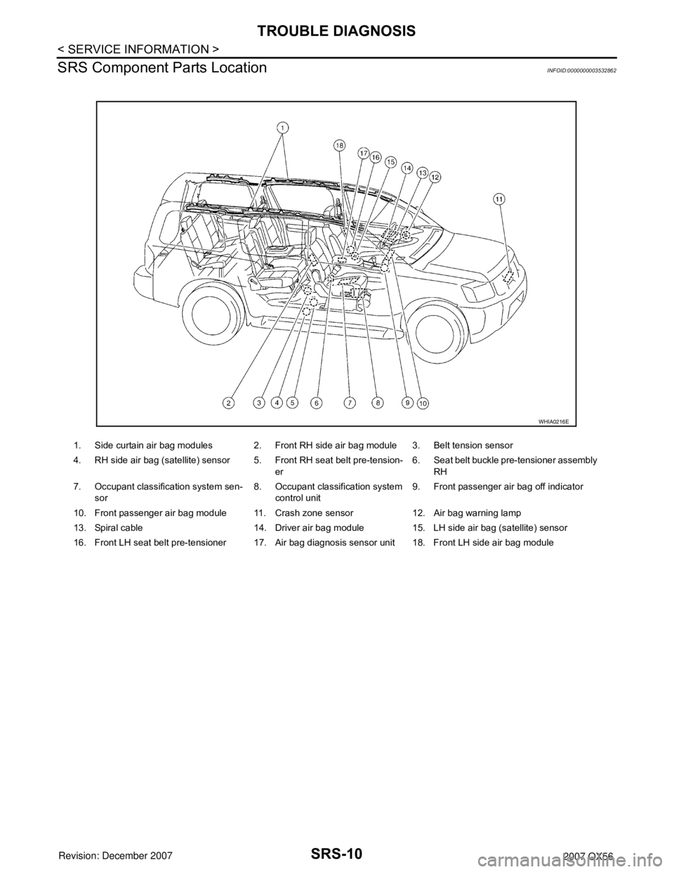
SRS Component Parts Location
INFOID:0000000003532862
1. Side curtain air bag modules 2. Front RH side air bag module 3. Belt tension sensor
4. RH side air bag (satellite) sensor 5. Front RH seat belt pre-tension-
er6. Seat belt buckle pre-tensioner assembly
RH
7. Occupant classification system sen-
sor8. Occupant classification system
control unit9. Front passenger air bag off indicator
10. Front passenger air bag module 11. Crash zone sensor 12. Air bag warning lamp
13. Spiral cable 14. Driver air bag module 15. LH side air bag (satellite) sensor
16. Front LH seat belt pre-tensioner 17. Air bag diagnosis sensor unit 18. Front LH side air bag module
WHIA0216E
Page 2796 of 3061

SRS-26
< SERVICE INFORMATION >
TROUBLE DIAGNOSIS
NOTE:
Follow the procedures in numerical order when repairing malfunctioning parts. Confirm whether malfunction is
eliminated using air bag warning lamp or CONSULT-II each time repair is finished. If malfunction is still
observed, proceed to the next step. When malfunction is eliminated, further repair work is not required.
DIAGNOSTIC PROCEDURE 3
Final Check of SRS Using CONSULT-II—Diagnosis Mode
Refer to GI-36, "CONSULT-II Start Procedure" .
OCCUPANT SENS C/U
[COMM FAIL]
[B1022]Communication between the occupant classification system
control unit and air bag diagnosis sensor unit is interrupted.1. Visually check the wiring harness
connection.
2. Replace the harness if it has visi-
ble damage.
3. Replace RH front seat cushion/
occupant classification system
control unit assembly.
4. Replace the air bag diagnosis
sensor unit.
5. Replace the related harness.
OCCUPANT SENS
[UNIT FAIL]
[B1018]Occupant classification sensor is malfunctioning. 1. Replace RH front seat cushion/
occupant classification system
control unit assembly.
BELT TENSION SENS
[UNIT FAIL]
[B1019]Belt tension sensor is malfunctioning. 1. Visually check the wiring harness
connection.
2. Replace the harness if it has visi-
ble damage.
3. Replace RH front seat belt as-
sembly.
4. Replace RH front seat cushion/
occupant classification system
control unit assembly.
5. Replace the related harness.
PASS A/B INDCTR CKT
[B1023]Front passenger air bag off indicator is malfunctioning. 1. Visually check the wiring harness
connection.
2. Replace the harness if it has visi-
ble damage.
3. Replace front passenger air bag
off indicator.
4. Replace the air bag diagnosis
sensor unit.
5. Replace the related harness.
FRONTAL COLLISION
DETECTION
[B1209]Driver and front passenger air bag modules are deployed. 1. Refer to SRS-49
.
SIDE COLLISION
DETECTION
[B1210]Side or curtain air bag modules are deployed (with side air
bags only).
ROLLOVER DETECTION
[B1211]Curtain air bag module and seat belt pre-tensioner are de-
ployed. Diagnostic item ExplanationRepair order
Recheck SRS at each replacement
Page 2823 of 3061

TF-1
DRIVELINE/AXLE
C
E
F
G
H
I
J
K
L
M
SECTION TF
A
B
TF
N
O
P
CONTENTS
TRANSFER
SERVICE INFORMATION ............................3
PRECAUTIONS ...................................................3
Precaution for Supplemental Restraint System
(SRS) "AIR BAG" and "SEAT BELT PRE-TEN-
SIONER" ...................................................................
3
Precaution for Transfer Assembly and Transfer
Control Unit Replacement .........................................
3
Precaution .................................................................4
Service Notice ...........................................................4
PREPARATION ...................................................6
Special Service Tool .................................................6
Commercial Service Tool ..........................................9
NOISE, VIBRATION AND HARSHNESS
(NVH) TROUBLESHOOTING ............................
10
NVH Troubleshooting Chart ....................................10
TRANSFER FLUID .............................................11
Replacement ...........................................................11
Inspection ................................................................11
ALL-MODE 4WD SYSTEM ................................12
Cross-Sectional View ..............................................12
Power Transfer ........................................................12
System Description .................................................14
Schematic ...............................................................19
CAN Communication ...............................................20
TROUBLE DIAGNOSIS .....................................21
How to Perform Trouble Diagnosis .........................21
Location of Electrical Parts ......................................22
Circuit Diagram .......................................................23
Wiring Diagram - T/F - .............................................24
Inspections Before Trouble Diagnosis ....................31
Trouble Diagnosis Chart by Symptom ....................34
Transfer Control Unit Input/Output Signal Refer-
ence Value ..............................................................
35
CONSULT-II Function (ALL MODE AWD/4WD) .....42
Self-Diagnosis Procedure .......................................48
TROUBLE DIAGNOSIS FOR SYSTEM ............51
Power Supply Circuit for Transfer Control Unit ........51
Transfer Control Unit ...............................................53
Output Shaft Revolution Signal (TCM) ....................53
Vehicle Speed Sensor (ABS) ..................................54
Neutral-4LO Switch .................................................54
4WD Shift Switch .....................................................57
Wait Detection Switch ..............................................60
PNP Switch Signal (TCM) .......................................63
Actuator Motor .........................................................64
Actuator Position Switch ..........................................69
Transfer Control Device ...........................................72
Engine Speed Signal (ECM) ....................................76
Clutch Pressure Solenoid ........................................76
2-4WD Solenoid ......................................................80
Transfer Motor .........................................................84
Transfer Fluid Temperature .....................................90
Clutch Pressure Switch ...........................................92
Line Pressure Switch ...............................................94
Throttle Position Signal (ECM) ................................97
ABS Operation Signal (ABS) ...................................97
VDC Operation Signal (ABS) ...................................98
TCS Operation Signal (ABS) ...................................98
CAN Communication Line .......................................99
ATP Switch ..............................................................99
TROUBLE DIAGNOSIS FOR SYMPTOMS ....102
4WD Shift Indicator Lamp and 4LO Indicator
Lamp Do Not Turn ON ...........................................
102
4WD Warning Lamp Does Not Turn ON ...............104
4WD Shift Indicator Lamp or 4LO Indicator Lamp
Does Not Change ..................................................
107
ATP Warning Lamp Turns ON ...............................109
4LO Indicator Lamp Repeats Flashing ..................110
4WD Warning Lamp Flashes Rapidly ....................111
4WD Warning Lamp Flashes Slowly .....................112
Heavy Tight-corner Braking Symptom Occurs ......113
4WD System Does Not Operate ............................114
TRANSFER CONTROL UNIT .........................115
Removal and Installation .......................................115
Page 2825 of 3061

PRECAUTIONS
TF-3
< SERVICE INFORMATION >
C
E
F
G
H
I
J
K
L
MA
B
TF
N
O
P
SERVICE INFORMATION
PRECAUTIONS
Precaution for Supplemental Restraint System (SRS) "AIR BAG" and "SEAT BELT
PRE-TENSIONER"
INFOID:0000000003532506
The Supplemental Restraint System such as “AIR BAG” and “SEAT BELT PRE-TENSIONER”, used along
with a front seat belt, helps to reduce the risk or severity of injury to the driver and front passenger for certain
types of collision. This system includes seat belt switch inputs and dual stage front air bag modules. The SRS
system uses the seat belt switches to determine the front air bag deployment, and may only deploy one front
air bag, depending on the severity of a collision and whether the front occupants are belted or unbelted.
Information necessary to service the system safely is included in the SRS and SB section of this Service Man-
ual.
WARNING:
• To avoid rendering the SRS inoperative, which could increase the risk of personal injury or death in
the event of a collision which would result in air bag inflation, all maintenance must be performed by
an authorized NISSAN/INFINITI dealer.
• Improper maintenance, including incorrect removal and installation of the SRS, can lead to personal
injury caused by unintentional activation of the system. For removal of Spiral Cable and Air Bag
Module, see the SRS section.
• Do not use electrical test equipment on any circuit related to the SRS unless instructed to in this
Service Manual. SRS wiring harnesses can be identified by yellow and/or orange harnesses or har-
ness connectors.
Precaution for Transfer Assembly and Transfer Control Unit ReplacementINFOID:0000000003532507
When replacing transfer assembly or transfer control unit, check the 4WD shift indicator lamp as follows.
1. Turn ignition switch “ON”.
2. Check 4WD shift indicator lamp is turned ON for approx. 1 second.
• If OK, the position between transfer assembly and transfer control unit is correct.
• If NG, the position is different between transfer assembly and transfer control unit.
Adjust the position between transfer assembly and transfer control unit. Refer to "METHOD FOR POSITION
ADJUSTMENT".
METHOD FOR POSITION ADJUSTMENT
1. Start engine. Run the engine for at least 10 seconds.
2. Stop vehicle and move A/T selector lever to “N” position with brake pedal depressed. Stay in "N" for at
least 2 seconds.
3. Turn 4WD shift switch to “2WD” position. Stay in "2WD" for at least 2 seconds.
4. Turn ignition switch “OFF”.
5. Start engine.
6. Erase self-diagnosis. Refer to TF-42, "
CONSULT-II Function (ALL MODE AWD/4WD)" (with CONSULT-II)
or TF-48, "
Self-Diagnosis Procedure" (without CONSULT-II).
7. Check 4WD shift indicator lamp. Refer to TF-31, "
Inspections Before Trouble Diagnosis".
If 4WD shift indicator lamp does not indicate "2WD", install new transfer control unit and retry the above
check.
Page 2839 of 3061

ALL-MODE 4WD SYSTEM
TF-17
< SERVICE INFORMATION >
C
E
F
G
H
I
J
K
L
MA
B
TF
N
O
P
*: After 2.5 seconds have elapsed.
• 4WD shift switch, PNP switch, Neutral-4LO switch, vehicle speed sensor and throttle position sensor are
used in conjunction with the transfer motor.
WAIT DETECTION SWITCH
• The wait detection switch operates when there is “circulating” torque produced in the propeller shaft (L→H)
or when there is a phase difference between 2-4 sleeve and clutch drum (H→L). After the release of the “cir-
culating” torque, the wait detection switch helps provide the 4WD lock gear (clutch drum) shifts. A difference
may occur between the operation of the 4WD shift switch and actual drive mode. At this point, the wait
detection switch senses an actual drive mode.
• The wait detection switch operates as follows.
- 4WD lock gear (clutch drum) locked: ON
- 4WD lock gear (clutch drum) released: OFF
• The wait detection switch senses an actual drive mode and the 4WD shift indicator lamp indicates the vehi-
cle drive mode.
NEUTRAL-4LO SWITCH
The neutral-4LO switch detects that transfer gear is in neutral or 4LO (or shifting from neutral to 4LO) condi-
tion by L-H shift fork position.
AT P S W I T C H
ATP switch detects if transfer gear is in a neutral condition by L-H shift fork position.
NOTE:
Transfer gear may be in a neutral condition in 4H-4LO.
2-4WD SHIFT SOLENOID VALVE
The 2-4WD shift solenoid valve operates to apply oil pressure to the wet-multiplate clutch, depending on the
drive mode. The driving force is transmitted to the front wheels through the clutch so the vehicle is set in the
4WD mode. Setting the vehicle in the 2WD mode requires no pressure buildup. In other words, pressure force
applied to the wet-multiplate clutch becomes zero.
CLUTCH PRESSURE SOLENOID VALVE
The clutch pressure solenoid valve distributes torque (front and rear) in AUTO mode.
4H (LOCK) and 4LO“N” position 0 — ON
“P” position 00 - 0.07/8 OFF*
0.07/8 - 1/8 HOLD
1/8 - MAX ON
Other than “R” position0 < VSS ≤ 50 km/h (31 MPH)
— ON
50 km/h (31 MPH) < VSS < 55
km/h (34 MPH) HOLD
55 km/h (34 MPH) ≤ VSS OFF
“R” position — — ON
“R” position — — ON
AUTO“P” or “N” position00 - 0.07/8 OFF*
0.07/8 - 1/8 HOLD
1/8 - MAX ON
0 < VSS ≤ 50 km/h (31 MPH)
— ON
50 km/h (31 MPH) < VSS < 55
km/h (34 MPH) HOLD
55 km/h (34 MPH) ≤ VSS OFF
Other than “R”, "P" and "N"
position0 < VSS ≤ 50 km/h (31 MPH)
— ON
50 km/h (31 MPH) < VSS < 55
km/h (34 MPH) HOLD
55 km/h (34 MPH) ≤ VSS OFF 4WD shift switch A/T selector lever positionVehicle speed
(VSS)Accelerator pedal positionMotor relay drive
command
Page 2840 of 3061

TF-18
< SERVICE INFORMATION >
ALL-MODE 4WD SYSTEM
LINE PRESSURE SWITCH
• With the transfer system design, control of the oil pressure provides the transmission of drive torque to the
front wheels. The main pressure to control the oil pressure is referred to as the line pressure.
• The line pressure switch determines whether or not adequate line pressure has built up under different oper-
ating conditions.
• The line pressure switch turns ON when line pressure is produced.
• The line pressure switch senses line pressure abnormalities and turns the 4WD warning lamp ON.
CLUTCH PRESSURE SWITCH
• The clutch pressure switch determines whether or not adequate clutch pressure has built up under different
operating conditions.
• The clutch pressure switch turns ON when clutch pressure is produced.
• The clutch pressure switch senses clutch pressure abnormalities and turns the 4WD warning lamp ON.
TRANSFER FLUID TEMPERATURE SENSOR
The transfer temperature sensor detects the transfer fluid temperature and sends a signal to the transfer con-
trol unit.
TRANSFER CONTROL UNIT
• Transfer control unit controls transfer control device by input signals of each sensor and each switch.
• Self-diagnosis can be done.
TRANSFER CONTROL DEVICE
The transfer control device changes the state of transfer assembly between 2WD, AUTO, 4H⇔4LO with the
2WD, AUTO, 4H and 4LO signals of 4WD shift switch.
NOTE:
• To shift between 4H⇔4LO, stop the vehicle, depress the brake pedal and shift the transmission selector to
the "N" position. Depress and turn the 4WD shift switch. The shift switch will not shift to the desired mode if
the transmission is not in "N" or the vehicle is moving. The 4LO indicator lamp will be lit when the 4LO is
engaged.
• Actuator motor and actuator position switch are integrated.
4WD SHIFT SWITCH AND INDICATOR LAMP
4WD Shift Switch
The 4WD shift switch allows selection from 2WD, AUTO, 4H or 4LO.
4WD Shift Indicator Lamp
• Displays driving conditions selected by 4WD shift switch with 2WD, AUTO and 4H indicators while engine is
running. (When 4WD warning lamp is turned on, all 4WD shift indicator lamps are turned off.)
• Turns ON for approximately 1 second when ignition switch is turned ON, for purpose of lamp check.
4LO Indicator Lamp
• Displays 4LO condition while engine is running. 4LO indicator lamp flashes if transfer gear does not shift
completely under 2WD, AUTO, 4H⇔4LO. (When 4WD warning lamp is turned on, 4LO indicator lamp is
turned off.)
• Turns ON for approximately 1 second when ignition switch is turned ON, for purpose of lamp check.
4WD WARNING LAMP
Turns ON or FLASH when there is a malfunction in 4WD system.
Also turns ON when ignition switch is turned ON, for purpose of lamp check. Turns OFF for approximately 1
second after the engine starts if system is normal.
4WD Warning Lamp Indication
Condition Content 4WD warning lamp
During self-diagnosis Indicates the malfunction position by number of flickers. Flickers at malfunction mode.
Lamp check*Checks the lamp by turning ON during engine starting. After
engine starts, it turns OFF if there are no malfunctions.ON
Malfunction in 4WD system*Turns ON to indicate malfunction. When ignition switch is
turned to “OFF” or the malfunction is corrected, it turns OFF.ON
When vehicle is driven with different
diameters of front and rear tiresFlickers once every 2 seconds.
Turns OFF when ignition switch is “OFF”.Flickers once every 2 sec-
onds.
Page 2841 of 3061

ALL-MODE 4WD SYSTEM
TF-19
< SERVICE INFORMATION >
C
E
F
G
H
I
J
K
L
MA
B
TF
N
O
P
*: When 4WD warning lamp is ON, all the 4WD shift indicator lamps turn OFF.
ATP WARNING LAMP
Even if A/T selector lever is in “P” position, vehicle may move because A/T parking mechanism does not oper-
ate when transfer is under neutral condition. ATP warning lamp is turned on so as to indicate this condition to
the driver.
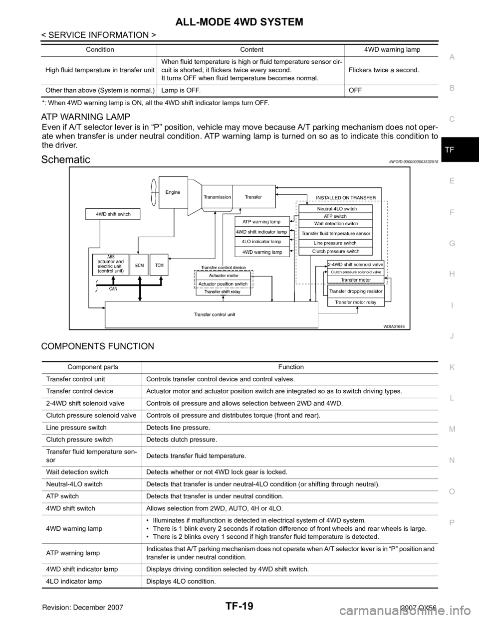
SchematicINFOID:0000000003532518
COMPONENTS FUNCTION
High fluid temperature in transfer unitWhen fluid temperature is high or fluid temperature sensor cir-
cuit is shorted, it flickers twice every second.
It turns OFF when fluid temperature becomes normal.Flickers twice a second.
Other than above (System is normal.) Lamp is OFF. OFFCondition Content 4WD warning lamp
WDIA0164E
Component parts Function
Transfer control unit Controls transfer control device and control valves.
Transfer control device Actuator motor and actuator position switch are integrated so as to switch driving types.
2-4WD shift solenoid valve Controls oil pressure and allows selection between 2WD and 4WD.
Clutch pressure solenoid valve Controls oil pressure and distributes torque (front and rear).
Line pressure switch Detects line pressure.
Clutch pressure switch Detects clutch pressure.
Transfer fluid temperature sen-
sorDetects transfer fluid temperature.
Wait detection switch Detects whether or not 4WD lock gear is locked.
Neutral-4LO switch Detects that transfer is under neutral-4LO condition (or shifting through neutral).
ATP switch Detects that transfer is under neutral condition.
4WD shift switch Allows selection from 2WD, AUTO, 4H or 4LO.
4WD warning lamp• Illuminates if malfunction is detected in electrical system of 4WD system.
• There is 1 blink every 2 seconds if rotation difference of front wheels and rear wheels is large.
• There is 2 blinks every 1 second if high transfer fluid temperature is detected.
AT P w a r n i n g l a m pIndicates that A/T parking mechanism does not operate when A/T selector lever is in “P” position and
transfer is under neutral condition.
4WD shift indicator lamp Displays driving condition selected by 4WD shift switch.
4LO indicator lamp Displays 4LO condition.
Page 2842 of 3061

TF-20
< SERVICE INFORMATION >
ALL-MODE 4WD SYSTEM
CAN Communication
INFOID:0000000003532519
SYSTEM DESCRIPTION
Refer to LAN-4.
ABS actuator and electric unit
(control unit)Transmits vehicle speed signal via CAN communication to transfer control unit.
TCMTransmits the following signals via CAN communication to transfer control unit.
• Output shaft revolution signal
• A/T position indicator signal (PNP switch signal)
ECMTransmits the following signals via CAN communication to transfer control unit.
• Engine speed signal
• Accelerator pedal position signal Component parts Function