2007 INFINITI QX56 service indicator
[x] Cancel search: service indicatorPage 2462 of 3061

PG-60
< SERVICE INFORMATION >
HARNESS
Code Section Wiring Diagram Name
A/C,A ATC Auto Air Conditioner
A/SUSP RSU Rear Air Suspension
AF1B1 EC Air Fuel Ratio (A/F) Sensor 1 (Bank 1)
AF1B2 EC Air Fuel Ratio (A/F) Sensor 1 (Bank 2)
AF1HB1 EC Air Fuel Ratio (A/F) Sensor 1 (Bank 1)
AF1HB2 EC Air Fuel Ratio (A/F) Sensor 1 (Bank 2)
APPS1 EC Accelerator Pedal Position Sensor
APPS2 EC Accelerator Pedal Position Sensor
APPS3 EC Accelerator Pedal Position Sensor
ASC/BS EC ASCD Brake Switch
ASC/SW EC ASCD Steering Switch
ASCBOF EC ASCD Brake Switch
ASCIND EC ASCD Indicator
A/T AT A/T Assembly
AT/IND DI A/T Indicator Lamp
AUDIO AV Audio
AUT/DP SE Automatic Drive Positioner
AUTO/L LT Auto Light Control
B/CLOS BL Back Door Auto Closure System
BACK/L LT Back-up Lamp
BRK/SW EC Brake Switch
CAN EC CAN Communication Line
CAN LAN CAN System
CHARGE SC Charging System
CHIME DI Warning Chime
CLOCK DI Clock
COOL/F EC Cooling Fan Control
COMBSW LT Combination Switch
COMM AV Audio Visual Communication System
COMPAS DI Compass and Thermometer
D/LOCK BL Power Door Lock
DEF GW Rear Window Defogger
DTRL LT Headlamp - With Daytime Light System
DVD AV DVD Entertainment System
ECM/PW EC ECM Power Supply for Back-Up
ECTS EC Engine Coolant Temperature Sensor
ETC1 EC Electric Throttle Control Function
ETC2 EC Throttle Control Motor Relay
ETC3 EC Throttle Control Motor
F/FOG LT Front Fog Lamp
F/PUMP EC Fuel Pump
FTTS EC Fuel Tank Temperature Sensor
FUELB1 EC Fuel Injection System Bank 1
FUELB2 EC Fuel Injection System Bank 2
H/AIM LT Headlamp Aiming Control
H/PHON AV Hands Free Telephone
H/LAMP LT Headlamp
HORN WW Horn
HSEAT SE Heated Seat
ICC ACS Intelligent Cruise Control
ICCBOF EC ICC Brake Switch
Page 2463 of 3061
HARNESS
PG-61
< SERVICE INFORMATION >
C
D
E
F
G
H
I
J
L
MA
B
PG
N
O
P
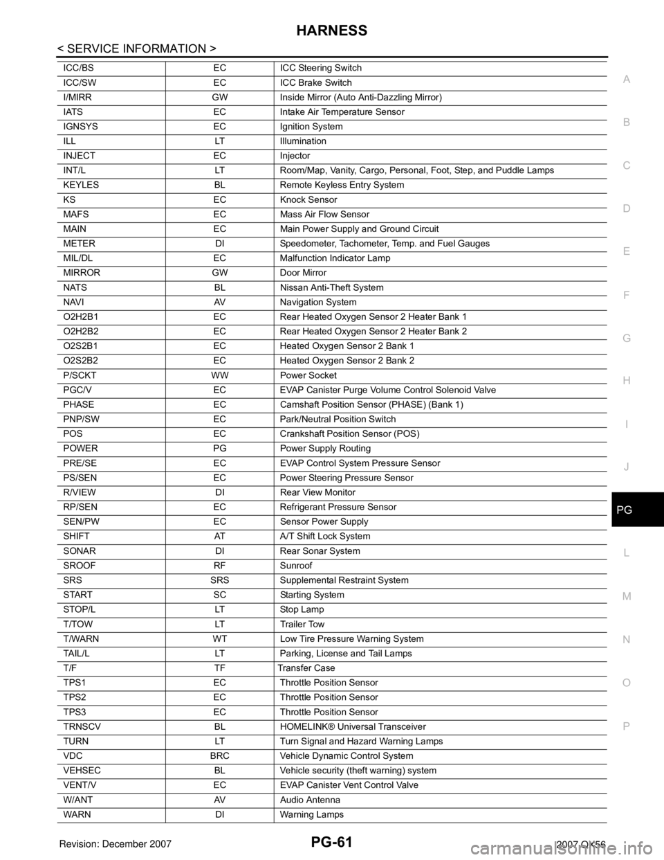
ICC/BS EC ICC Steering Switch
ICC/SW EC ICC Brake Switch
I/MIRR GW Inside Mirror (Auto Anti-Dazzling Mirror)
IATS EC Intake Air Temperature Sensor
IGNSYS EC Ignition System
ILL LT Illumination
INJECT EC Injector
INT/L LT Room/Map, Vanity, Cargo, Personal, Foot, Step, and Puddle Lamps
KEYLES BL Remote Keyless Entry System
KS EC Knock Sensor
MAFS EC Mass Air Flow Sensor
MAIN EC Main Power Supply and Ground Circuit
METER DI Speedometer, Tachometer, Temp. and Fuel Gauges
MIL/DL EC Malfunction Indicator Lamp
MIRROR GW Door Mirror
NATS BL Nissan Anti-Theft System
NAVI AV Navigation System
O2H2B1 EC Rear Heated Oxygen Sensor 2 Heater Bank 1
O2H2B2 EC Rear Heated Oxygen Sensor 2 Heater Bank 2
O2S2B1 EC Heated Oxygen Sensor 2 Bank 1
O2S2B2 EC Heated Oxygen Sensor 2 Bank 2
P/SCKT WW Power Socket
PGC/V EC EVAP Canister Purge Volume Control Solenoid Valve
PHASE EC Camshaft Position Sensor (PHASE) (Bank 1)
PNP/SW EC Park/Neutral Position Switch
POS EC Crankshaft Position Sensor (POS)
POWER PG Power Supply Routing
PRE/SE EC EVAP Control System Pressure Sensor
PS/SEN EC Power Steering Pressure Sensor
R/VIEW DI Rear View Monitor
RP/SEN EC Refrigerant Pressure Sensor
SEN/PW EC Sensor Power Supply
SHIFT AT A/T Shift Lock System
SONAR DI Rear Sonar System
SROOF RF Sunroof
SRS SRS Supplemental Restraint System
START SC Starting System
STOP/L LT Stop Lamp
T/TOW LT Trailer Tow
T/WARN WT Low Tire Pressure Warning System
TAIL/L LT Parking, License and Tail Lamps
T/F TF Transfer Case
TPS1 EC Throttle Position Sensor
TPS2 EC Throttle Position Sensor
TPS3 EC Throttle Position Sensor
TRNSCV BL HOMELINK® Universal Transceiver
TURN LT Turn Signal and Hazard Warning Lamps
VDC BRC Vehicle Dynamic Control System
VEHSEC BL Vehicle security (theft warning) system
VENT/V EC EVAP Canister Vent Control Valve
W/ANT AV Audio Antenna
WARN DI Warning Lamps
Page 2574 of 3061

REAR FINAL DRIVE ASSEMBLY
RFD-17
< SERVICE INFORMATION >
C
E
F
G
H
I
J
K
L
MA
B
RFD
N
O
P
ASSEMBLY INSPECTION AND ADJUSTMENT
• Drain the differential gear oil before inspection and adjustment. Refer to RFD-8.
• Remove and install the carrier cover as necessary for inspection and adjustment. Refer to RFD-13
.
Total Preload Torque
1. Remove the side flanges if necessary.
CAUTION:
The side flanges shaft must removed in order to measure total preload torque.
2. Rotate the drive pinion back and forth 2 to 3 times to check for unusual noise and rotation malfunction.
3. Rotate the drive pinion at least 20 times to check for smooth operation of the bearings.
4. Measure the total preload torque using Tool.
NOTE:
Total preload torque = Drive pinion bearing preload torque +
Side bearing preload torque
• If the measured value is out of the specification, check and adjust each part. Adjust the drive pinion
bearing preload torque first, then adjust the side bearing preload torque.
CAUTION:
Select a side bearing adjusting washer for right and left individually.
Drive Gear Runout
1. Fit a dial indicator to the drive gear back face.
2. Rotate the drive gear to measure runout.
• If the runout is outside of the limit, check the condition of the drive
gear assembly. Foreign material may be caught between the drive
gear and differential case, or the differential case or drive gear may
be deformed.
CAUTION:
Replace drive gear and drive pinion as a set.
Tooth Contact
19. Side bearing adjusting washer 20. Bearing cap 21. Carrier cover
22. Filler plug 23. Drain plug 24. Side oil seal
Tool number : ST3127S000 (J-25765-A)
Total preload torque:
2.05 - 4.11 N·m (0.21 - 0.42 kg-m, 19 - 36 in-lb)
SPD884
If the total preload torque is greater than specification
On drive pinion bearings: Replace the collapsible spacer.
On side bearings: Use thinner side bearing adjusting washers by the same
amount on each side. Refer to RFD-32, "
Inspection and Adjust-
ment".
If the total preload torque is less than specification
On drive pinion bearings: Tighten the drive pinion lock nut.
On side bearings: Use thicker side bearing adjusting washers by the same
amount on each side. Refer to RFD-32, "
Inspection and Adjust-
ment".
Runout limit : 0.05 mm (0.0020 in) or less
SPD886
Page 2576 of 3061
REAR FINAL DRIVE ASSEMBLY
RFD-19
< SERVICE INFORMATION >
C
E
F
G
H
I
J
K
L
MA
B
RFD
N
O
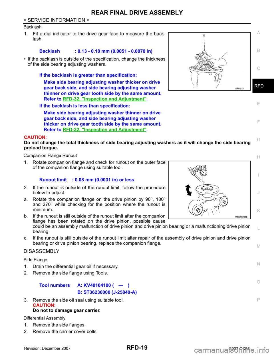
P Backlash
1. Fit a dial indicator to the drive gear face to measure the back-
lash.
• If the backlash is outside of the specification, change the thickness
of the side bearing adjusting washers.
CAUTION:
Do not change the total thickness of side bearing adjusting washers as it will change the side bearing
preload torque.
Companion Flange Runout
1. Rotate companion flange and check for runout on the outer face
of the companion flange using suitable tool.
2. If the runout is outside of the runout limit, follow the procedure
below to adjust.
a. Rotate the companion flange on the drive pinion by 90°, 180°
and 270° while checking for the position where the runout is
minimum.
b. If the runout is still outside of the runout limit after the companion
flange has been rotated on the drive pinion, possible cause
could be an assembly malfunction of drive pinion and drive pinion bearing or a malfunctioning drive pinion
bearing.
c. If the runout is still outside of the runout limit after repair of the assembly of drive pinion and drive pinion
bearing or drive pinion bearing, replace the companion flange.
DISASSEMBLY
Side Flange
1. Drain the differential gear oil if necessary.
2. Remove the side flange using Tools.
3. Remove the side oil seal using suitable tool.
CAUTION:
Do not to damage gear carrier.
Differential Assembly
1. Remove the side flanges.
2. Remove the carrier cover bolts.Backlash : 0.13 - 0.18 mm (0.0051 - 0.0070 in)
If the backlash is greater than specification:
Make side bearing adjusting washer thicker on drive
gear back side, and side bearing adjusting washer
thinner on drive gear tooth side by the same amount.
Refer to RFD-32, "
Inspection and Adjustment".
If the backlash is less than specification:
Make side bearing adjusting washer thinner on drive
gear back side, and side bearing adjusting washer
thicker on drive gear tooth side by the same amount.
Refer to RFD-32, "
Inspection and Adjustment".
SPD513
Runout limit : 0.08 mm (0.0031 in) or less
WDIA0231E
Tool numbers A: KV40104100 ( — )
B: ST36230000 (J-25840-A)
Page 2591 of 3061
RSU-1
SUSPENSION
C
D
F
G
H
I
J
K
L
M
SECTION RSU
A
B
RSU
N
O
PCONTENTS
REAR SUSPENSION
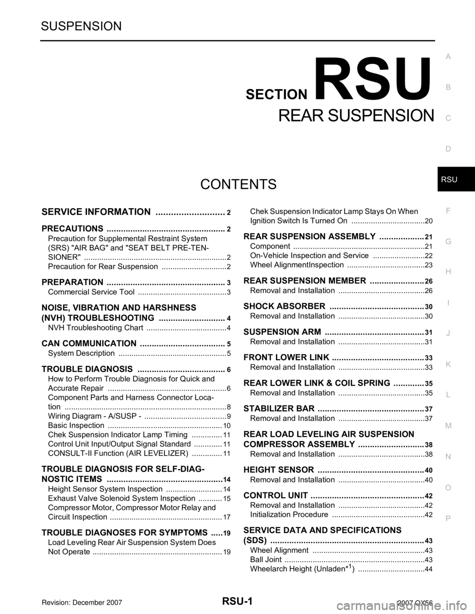
SERVICE INFORMATION ............................2
PRECAUTIONS ...................................................2
Precaution for Supplemental Restraint System
(SRS) "AIR BAG" and "SEAT BELT PRE-TEN-
SIONER" ...................................................................
2
Precaution for Rear Suspension ...............................2
PREPARATION ...................................................3
Commercial Service Tool ..........................................3
NOISE, VIBRATION AND HARSHNESS
(NVH) TROUBLESHOOTING .............................
4
NVH Troubleshooting Chart ......................................4
CAN COMMUNICATION .....................................5
System Description ...................................................5
TROUBLE DIAGNOSIS ......................................6
How to Perform Trouble Diagnosis for Quick and
Accurate Repair ........................................................
6
Component Parts and Harness Connector Loca-
tion ............................................................................
8
Wiring Diagram - A/SUSP - .......................................9
Basic Inspection ......................................................10
Chek Suspension Indicator Lamp Timing ...............11
Control Unit Input/Output Signal Standard ..............11
CONSULT-II Function (AIR LEVELIZER) ...............11
TROUBLE DIAGNOSIS FOR SELF-DIAG-
NOSTIC ITEMS ..................................................
14
Height Sensor System Inspection ...........................14
Exhaust Valve Solenoid System Inspection ............15
Compressor Motor, Compressor Motor Relay and
Circuit Inspection .....................................................
17
TROUBLE DIAGNOSES FOR SYMPTOMS ......19
Load Leveling Rear Air Suspension System Does
Not Operate .............................................................
19
Chek Suspension Indicator Lamp Stays On When
Ignition Switch Is Turned On ...................................
20
REAR SUSPENSION ASSEMBLY ...................21
Component ..............................................................21
On-Vehicle Inspection and Service .........................22
Wheel AlignmentInspection .....................................23
REAR SUSPENSION MEMBER .......................26
Removal and Installation .........................................26
SHOCK ABSORBER ........................................30
Removal and Installation .........................................30
SUSPENSION ARM ..........................................31
Removal and Installation .........................................31
FRONT LOWER LINK .......................................33
Removal and Installation .........................................33
REAR LOWER LINK & COIL SPRING .............35
Removal and Installation .........................................35
STABILIZER BAR .............................................37
Removal and Installation .........................................37
REAR LOAD LEVELING AIR SUSPENSION
COMPRESSOR ASSEMBLY ............................
38
Removal and Installation .........................................38
HEIGHT SENSOR .............................................40
Removal and Installation .........................................40
CONTROL UNIT ................................................42
Removal and Installation .........................................42
Initialization Procedure ............................................42
SERVICE DATA AND SPECIFICATIONS
(SDS) .................................................................
43
Wheel Alignment .....................................................43
Ball Joint ..................................................................43
Wheelarch Height (Unladen*1) ................................44
Page 2601 of 3061
TROUBLE DIAGNOSIS
RSU-11
< SERVICE INFORMATION >
C
D
F
G
H
I
J
K
L
MA
B
RSU
N
O
P
POWER SYSTEM TERMINAL LOOSENESS AND BATTERY INSPECTION
Make sure the battery positive cable, negative cable and ground connection are not loose. In addition, make
sure the battery is sufficiently charged.
CK SUSP INDICATOR LAMP INSPECTION
1. Make sure the CK SUSP indicator lamp turns on for approximately 2 seconds when the ignition switch is
turned ON. If it does not, check the combination meter. Refer to DI-5
.
2. Make sure the lamp turns off approximately 2 seconds after the ignition switch is turned ON. If the lamp
does not turn off, conduct self-diagnosis of the suspension control unit.
3. After conducting the self-diagnosis, be sure to erase the error memory. Refer to RSU-11, "
CONSULT-II
Function (AIR LEVELIZER)" .
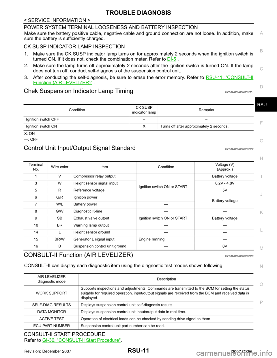
Chek Suspension Indicator Lamp TimingINFOID:0000000003532661
X: ON
—: OFF
Control Unit Input/Output Signal StandardINFOID:0000000003532662
CONSULT-II Function (AIR LEVELIZER)INFOID:0000000003532663
CONSULT-II can display each diagnostic item using the diagnostic test modes shown following.
CONSULT-II START PROCEDURE
Refer to GI-36, "CONSULT-II Start Procedure".
ConditionCK SUSP
indicator lampRemarks
Ignition switch OFF – –
Ignition switch ON X Turns off after approximately 2 seconds.
Te r m i n a l
No.Wire color Item ConditionVoltage (V)
(Approx.)
1 V Compressor relay output
Ignition switch ON or STARTBattery voltage
3 W Height sensor signal input 0.2V - 4.8V
5 R Reference voltage 5V
6 G/R Ignition power
Battery voltage
7W/LBattery power —
8 G/W Diagnostic K-line — —
9 SB Exhaust valve output Ignition switch ON or START Battery voltage
10 BR Warning lamp output — —
14 L Height sensor ground — —
15 BR/W Generator L signal input Engine running —
16 B Suspension control unit ground — 0V
AIR LEVELIZER
diagnostic modeDescription
WORK SUPPORTSupports inspections and adjustments. Commands are transmitted to the BCM for setting the status
suitable for required operation, input/output signals are received from the BCM and received data is
displayed.
SELF-DIAG RESULTS Displays suspension control unit self-diagnosis results.
DATA MONITOR Displays suspension control unit input/output data in real time.
ACTIVE TEST Operation of electrical loads can be checked by sending drive signal to them.
ECU PART NUMBER Suspension control unit part number can be read.
Page 2610 of 3061

RSU-20
< SERVICE INFORMATION >
TROUBLE DIAGNOSES FOR SYMPTOMS
2. Check voltage between suspension control unit connector B3
terminal 15 and ground.
OK or NG
OK >> Replace the suspension control unit. Refer to RSU-42.
NG >> Repair the circuit.
Chek Suspension Indicator Lamp Stays On When Ignition Switch Is Turned On
INFOID:0000000003532668
1.CARRY OUT SELF-DIAGNOSIS
Carry out self-diagnosis. Refer to RSU-11, "
CONSULT-II Function (AIR LEVELIZER)".
Are malfunctions detected in self-diagnosis?
YES >> Refer to RSU-11, "CONSULT-II Function (AIR LEVELIZER)" .
NO >> Refer to DI-26
. Voltage : Approx. 12V
WEIA0071E
Page 2614 of 3061
RSU-24
< SERVICE INFORMATION >
REAR SUSPENSION ASSEMBLY
• Check with the manufacturer of your specific alignment machine for their recommended Service/Cali-
bration Schedule.
THE ALIGNMENT PROCESS
IMPORTANT: Use only the alignment specifications listed in this Service Manual. Refer to FSU-19, "Wheel
Alignment (Unladen*1) *6" .
1. When displaying the alignment settings, many alignment machines use “indicators”: (Green/red, plus or
minus, Go/No Go). Do NOT use these indicators.
• The alignment specifications programmed into your alignment machine that operate these indicators
may not be correct.
• This may result in an ERROR.
2. Some newer alignment machines are equipped with an optional “Rolling Compensation” method to “com-
pensate” the sensors (alignment targets or head units). Do NOT use this “Rolling Compensation”
method.
• Use the “Jacking Compensation” method. After installing the alignment targets or head units, raise the
vehicle and rotate the wheels 1/2 turn both ways.
• See Instructions in the alignment machine you are using for more information.
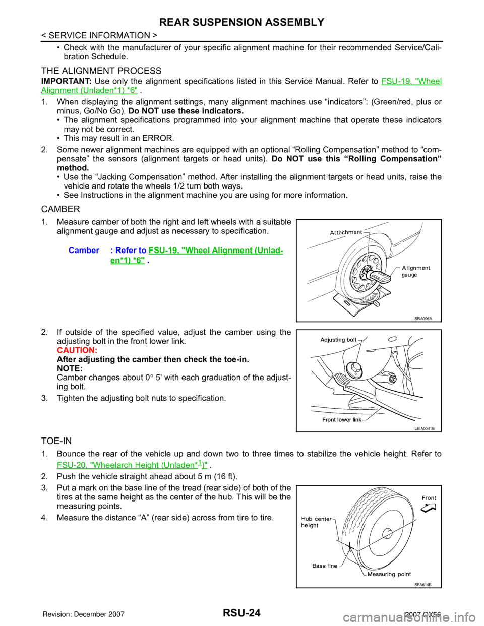
CAMBER
1. Measure camber of both the right and left wheels with a suitable
alignment gauge and adjust as necessary to specification.
2. If outside of the specified value, adjust the camber using the
adjusting bolt in the front lower link.
CAUTION:
After adjusting the camber then check the toe-in.
NOTE:
Camber changes about 0° 5' with each graduation of the adjust-
ing bolt.
3. Tighten the adjusting bolt nuts to specification.
TOE-IN
1. Bounce the rear of the vehicle up and down two to three times to stabilize the vehicle height. Refer to
FSU-20, "
Wheelarch Height (Unladen*1)" .
2. Push the vehicle straight ahead about 5 m (16 ft).
3. Put a mark on the base line of the tread (rear side) of both of the
tires at the same height as the center of the hub. This will be the
measuring points.
4. Measure the distance “A” (rear side) across from tire to tire.Camber : Refer to FSU-19, "
Wheel Alignment (Unlad-
en*1) *6" .
SRA096A
LEIA0041E
SFA614B