2007 INFINITI QX56 service indicator
[x] Cancel search: service indicatorPage 2673 of 3061

SE-1
BODY
C
D
E
F
G
H
J
K
L
M
SECTION SE
A
B
SE
N
O
P
CONTENTS
SEAT
SERVICE INFORMATION ............................3
PRECAUTIONS ...................................................3
Precaution for Supplemental Restraint System
(SRS) "AIR BAG" and "SEAT BELT PRE-TEN-
SIONER" ...................................................................
3
Precaution for Work ..................................................3
PREPARATION ...................................................4
Special Service Tool .................................................4
Commercial Service Tool ..........................................4
SQUEAK AND RATTLE TROUBLE DIAGNO-
SIS .......................................................................
5
Work Flow .................................................................5
Generic Squeak and Rattle Troubleshooting ............7
Diagnostic Worksheet ...............................................9
AUTOMATIC DRIVE POSITIONER ...................11
Component Parts and Harness Connector Loca-
tion ..........................................................................
11
System Description .................................................11
CAN Communication System Description ...............13
Schematic ...............................................................13
Wiring Diagram - AUT/DP - .....................................15
Terminal and Reference Value for BCM .................24
Driver Seat Control Unit Harness Connector Ter-
minal Layout ............................................................
25
Terminal and Reference Value for Driver Seat
Control Unit .............................................................
25
Automatic Drive Positioner Control Unit Harness
Connector Terminal Layout .....................................
28
Terminal and Reference Value for Automatic
Drive Positioner Control Unit ...................................
28
Work Flow ...............................................................30
Preliminary Check ...................................................30
BCM Power Supply and Ground Circuit Inspection
....
31
Power Supply and Ground Circuit Inspection .........31
CONSULT-II Function (AUTO DRIVE POS.) ..........32
CAN Communication Inspection Using CON-
SULT-II (Self-Diagnosis) ..........................................
35
Symptom Chart ........................................................35
Sliding Motor Circuit Inspection ...............................37
Reclining Motor LH Circuit Inspection .....................38
Lifting Motor (Front) Circuit Inspection ....................39
Lifting Motor (Rear) Circuit Inspection .....................40
Pedal Adjusting Motor Circuit Inspection .................41
Mirror Motor LH Circuit Inspection ...........................42
Mirror Motor RH Circuit Inspection ..........................44
Steering Wheel Tilt Circuit Inspection ......................45
Sliding Sensor Circuit Inspection .............................46
Reclining Sensor Circuit Inspection .........................47
Lifting Sensor (Front) Circuit Inspection ..................48
Lifting Sensor (Rear) Circuit Inspection ...................49
Pedal Adjusting Sensor Circuit Inspection ...............50
Mirror Sensor LH Circuit Inspection .........................51
Mirror Sensor RH Circuit Inspection ........................53
Steering Wheel Tilt Sensor Circuit Inspection .........54
Sliding Switch Circuit Inspection ..............................55
Reclining Switch Inspection .....................................56
Lifting Switch (Front) Circuit Inspection ...................58
Lifting Switch (Rear) Circuit Inspection ....................59
Power Seat Switch Ground Inspection ....................60
Pedal Adjusting Switch Circuit Inspection ...............61
Door Mirror Remote Control Switch (Changeover
Switch) Circuit Inspection ........................................
62
Door Mirror Remote Control Switch (Mirror
Switch) Circuit Inspection ........................................
64
Door Mirror Remote Control Switch Ground Circuit
Inspection ................................................................
65
Seat Memory Switch Circuit Inspection ...................66
Seat Memory Indicator Lamp Circuit Inspection ......67
Door Mirror Sensor Power Supply and Ground
Circuit inspection .....................................................
69
A/T Device (Park Position Switch) Circuit Inspec-
tion ...........................................................................
69
Steering Wheel Tilt Switch Circuit Inspection ..........70
Front Door Switch LH Circuit Inspection ..................72
UART Communication Line Circuit Inspection ........73
Page 2702 of 3061
SE-30
< SERVICE INFORMATION >
AUTOMATIC DRIVE POSITIONER
Work Flow
INFOID:0000000003533166
1. Check the symptom and customer's requests.
2. Understand the system description. Refer to SE-11, "
System Description".
3. Perform the preliminary check. Refer to SE-30, "
Preliminary Check" .
4. Check the self-diagnosis, results using CONSULT-II. Refer to SE-32, "
CONSULT-II Function (AUTO
DRIVE POS.)".
5. Repair or replace depending on the self-diagnostic results.
6. Based on the trouble diagnosis chart, repair or replace the cause of the malfunction. Refer to SE-35,
"Symptom Chart" .
7. Does the automatic drive positioner system operate normally?
If it is normal, GO TO 8.
If it is not normal, GO TO 3.
8. Inspection End.
Preliminary CheckINFOID:0000000003533167
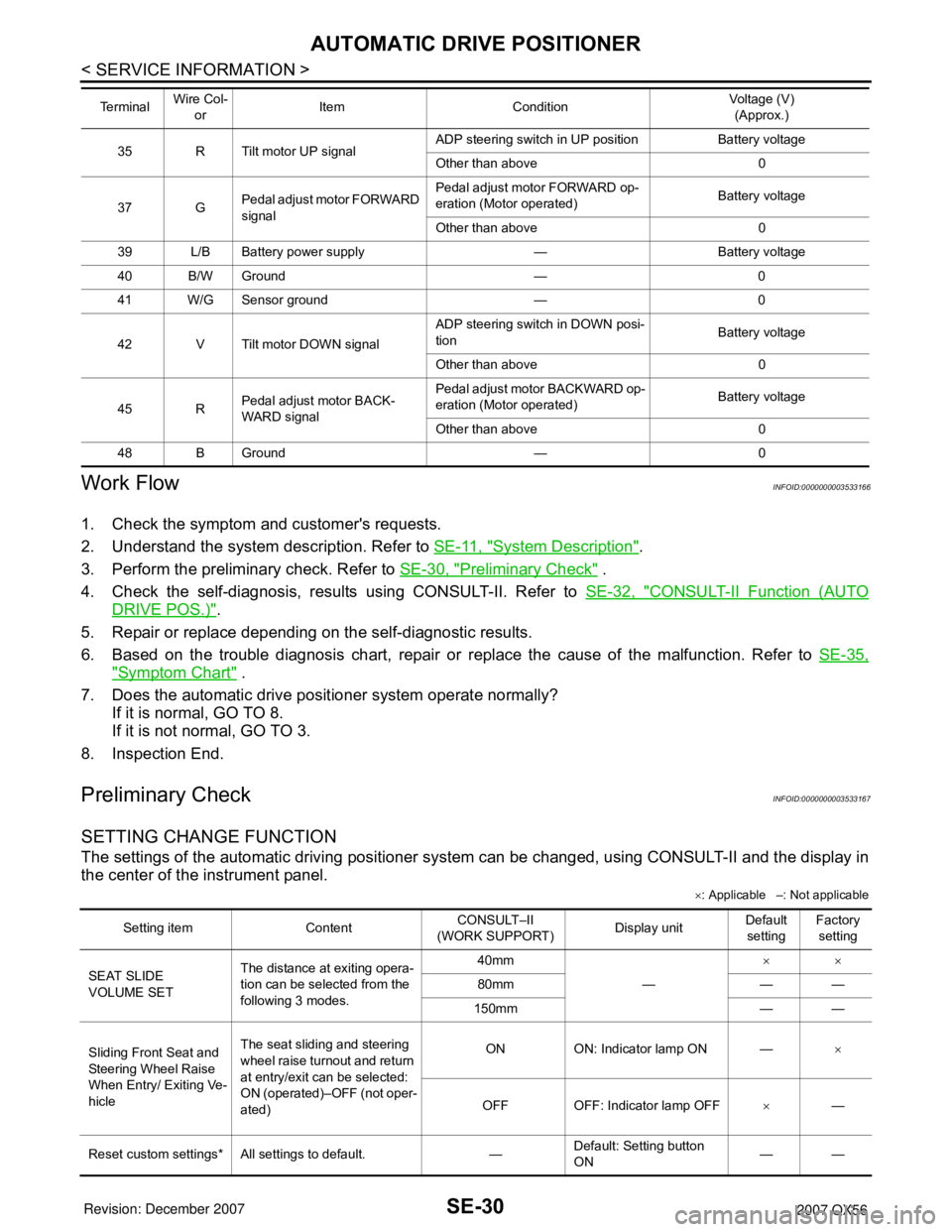
SETTING CHANGE FUNCTION
The settings of the automatic driving positioner system can be changed, using CONSULT-II and the display in
the center of the instrument panel.
×: Applicable –: Not applicable
35 R Tilt motor UP signalADP steering switch in UP position Battery voltage
Other than above 0
37 GPedal adjust motor FORWARD
signalPedal adjust motor FORWARD op-
eration (Motor operated)Battery voltage
Other than above 0
39 L/B Battery power supply — Battery voltage
40 B/W Ground — 0
41 W/G Sensor ground — 0
42 V Tilt motor DOWN signalADP steering switch in DOWN posi-
tionBattery voltage
Other than above 0
45 RPedal adjust motor BACK-
WARD signalPedal adjust motor BACKWARD op-
eration (Motor operated)Battery voltage
Other than above 0
48 B Ground — 0 Te r m i n a l Wire Col-
orItem ConditionVoltage (V)
(Approx.)
Setting item ContentCONSULT–II
(WORK SUPPORT)Display unitDefault
settingFactory
setting
SEAT SLIDE
VOLUME SETThe distance at exiting opera-
tion can be selected from the
following 3 modes.40mm
—××
80mm — —
150mm — —
Sliding Front Seat and
Steering Wheel Raise
When Entry/ Exiting Ve-
hicleThe seat sliding and steering
wheel raise turnout and return
at entry/exit can be selected:
ON (operated)–OFF (not oper-
ated)ON ON: Indicator lamp ON —×
OFF OFF: Indicator lamp OFF×—
Reset custom settings* All settings to default. —Default: Setting button
ON——
Page 2703 of 3061
AUTOMATIC DRIVE POSITIONER
SE-31
< SERVICE INFORMATION >
C
D
E
F
G
H
J
K
L
MA
B
SE
N
O
P
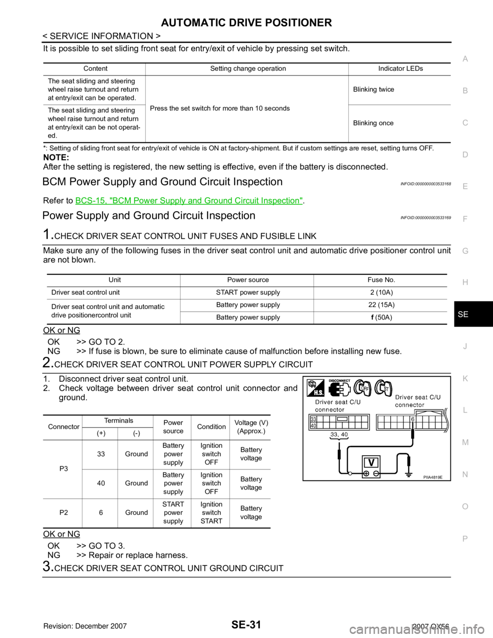
It is possible to set sliding front seat for entry/exit of vehicle by pressing set switch.
*: Setting of sliding front seat for entry/exit of vehicle is ON at factory-shipment. But if custom settings are reset, setting turns OFF.
NOTE:
After the setting is registered, the new setting is effective, even if the battery is disconnected.
BCM Power Supply and Ground Circuit InspectionINFOID:0000000003533168
Refer to BCS-15, "BCM Power Supply and Ground Circuit Inspection".
Power Supply and Ground Circuit InspectionINFOID:0000000003533169
1.CHECK DRIVER SEAT CONTROL UNIT FUSES AND FUSIBLE LINK
Make sure any of the following fuses in the driver seat control unit and automatic drive positioner control unit
are not blown.
OK or NG
OK >> GO TO 2.
NG >> If fuse is blown, be sure to eliminate cause of malfunction before installing new fuse.
2.CHECK DRIVER SEAT CONTROL UNIT POWER SUPPLY CIRCUIT
1. Disconnect driver seat control unit.
2. Check voltage between driver seat control unit connector and
ground.
OK or NG
OK >> GO TO 3.
NG >> Repair or replace harness.
3.CHECK DRIVER SEAT CONTROL UNIT GROUND CIRCUIT
Content Setting change operation Indicator LEDs
The seat sliding and steering
wheel raise turnout and return
at entry/exit can be operated.
Press the set switch for more than 10 secondsBlinking twice
The seat sliding and steering
wheel raise turnout and return
at entry/exit can be not operat-
ed.Blinking once
Unit Power source Fuse No.
Driver seat control unit START power supply 2 (10A)
Driver seat control unit and automatic
drive positionercontrol unitBattery power supply 22 (15A)
Battery power supplyf (50A)
ConnectorTe r m i n a l s
Power
sourceConditionVoltage (V)
(Approx.)
(+) (-)
P333 GroundBattery
power
supplyIgnition
switch
OFFBattery
voltage
40 GroundBattery
power
supplyIgnition
switch
OFFBattery
voltage
P2 6 GroundSTART
power
supplyIgnition
switch
STARTBattery
voltage
PIIA4819E
Page 2707 of 3061
AUTOMATIC DRIVE POSITIONER
SE-35
< SERVICE INFORMATION >
C
D
E
F
G
H
J
K
L
MA
B
SE
N
O
P
If active test is performed, reset seat memory and automatic drive positioner seat memory after performing
work.
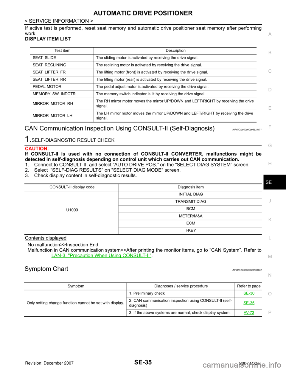
DISPLAY ITEM LIST
CAN Communication Inspection Using CONSULT-II (Self-Diagnosis)INFOID:0000000003533171
1.SELF-DIAGNOSTIC RESULT CHECK
CAUTION:
If CONSULT-II is used with no connection of CONSULT-II CONVERTER, malfunctions might be
detected in self-diagnosis depending on control unit which carries out CAN communication.
1. Connect to CONSULT-II, and select “AUTO DRIVE POS.” on the “SELECT DIAG SYSTEM” screen.
2. Select “SELF-DIAG RESULTS” on "SELECT DIAG MODE" screen.
3. Check display content in self-diagnostic results.
Contents displayed
No malfunction>>Inspection End.
Malfunction in CAN communication system>>After printing the monitor items, go to “CAN System”. Refer to
LAN-3, "
Precaution When Using CONSULT-II".
Symptom ChartINFOID:0000000003533172
Test item Description
SEAT SLIDE The sliding motor is activated by receiving the drive signal.
SEAT RECLINING The reclining motor is activated by receiving the drive signal.
SEAT LIFTER FR The lifting motor (front) is activated by receiving the drive signal.
SEAT LIFTER RR The lifting motor (rear) is activated by receiving the drive signal.
PEDAL MOTOR The pedal adjust motor is activated by receiving the drive signal.
MEMORY SW INDCTR The memory switch indicator is lit by receiving the drive signal.
MIRROR MOTOR RHThe RH mirror motor moves the mirror UP/DOWN and LEFT/RIGHT by receiving the drive
signal.
MIRROR MOTOR LHThe LH mirror motor moves the mirror UP/DOWN and LEFT/RIGHT by receiving the drive
signal.
CONSULT-II display code Diagnosis item
U1000INITIAL DIAG
TRANSMIT DIAG
BCM
METER/M&A
ECM
I-KEY
Symptom Diagnoses / service procedure Refer to page
Only setting change function cannot be set with display.1. Preliminary checkSE-30
2. CAN communication inspection using CONSULT-II (self-
diagnosis)SE-35
3. If the above systems are normal, check display system.AV- 7 3
Page 2708 of 3061
SE-36
< SERVICE INFORMATION >
AUTOMATIC DRIVE POSITIONER
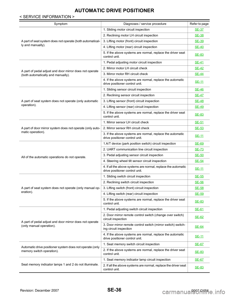
A part of seat system does not operate (both automatical-
ly and manually).1. Sliding motor circuit inspection SE-37
2. Reclining motor LH circuit inspection SE-38
3. Lifting motor (front) circuit inspectionSE-39
4. Lifting motor (rear) circuit inspectionSE-40
5. If the above systems are normal, replace the driver seat
control unit.SE-83
A part of pedal adjust and door mirror does not operate
(both automatically and manually).1. Pedal adjusting motor circuit inspectionSE-412. Mirror motor LH circuit check SE-42
3. Mirror motor RH circuit check SE-44
4. If the above systems are normal, replace the automatic
drive positioner control unit.SE-11
A part of seat system does not operate (only automatic
operation).1. Sliding sensor circuit inspectionSE-46
2. Reclining sensor circuit inspectionSE-47
3. Lifting sensor (front) circuit inspectionSE-48
4. Lifting sensor (rear) circuit inspectionSE-49
5. If the above systems are normal, replace the driver seat
control unit.SE-83
A part of door mirror system does not operate (only auto-
matic operation).1. Mirror sensor LH circuit checkSE-512. Mirror sensor RH circuit checkSE-53
3. If the above systems are normal, replace the automatic
drive positioner control unit.SE-11
All of the automatic operations do not operate.1.A/T device (park position switch) circuit inspectionSE-69
2. UART communication line circuit inspectionSE-73
3. Pedal adjusting sensor circuit inspectionSE-50
4. Steering wheel tilt sensor circuit inspectionSE-54
4. If all the above systems are normal, replace the automatic
drive positioner control unit.SE-11
A part of seat system does not operate (only manual op-
eration).1. Sliding switch circuit inspectionSE-55
2. Reclining switch circuit inspectionSE-56
3. Lifting switch (front) circuit inspectionSE-58
4. Lifting switch (rear) circuit inspectionSE-59
5. If the above systems are normal, replace the driver seat
control unit.SE-83
A part of pedal adjust and door mirror does not operate
(only manual operation).1. Pedal adjusting switch circuit inspection SE-61
2. Door mirror remote control switch (change over switch)
circuit inspection SE-62
3. Door mirror remote control switch (mirror switch) switch-
ing circuit inspection SE-64
4. If the above systems are normal, replace the automatic
drive positioner control unit.SE-11
Automatic drive positioner system does not operate (only
memory switch operation).1. Seat memory switch circuit inspectionSE-672. If the above systems are normal, replace the driver seat
control unit.SE-83
Seat memory indicator lamps 1 and 2 do not illuminate.1. Seat memory indicator lamp circuit inspectionSE-672. If all the above systems are normal, replace the driver seat
control unit.SE-83
Symptom Diagnoses / service procedure Refer to page
Page 2739 of 3061
AUTOMATIC DRIVE POSITIONER
SE-67
< SERVICE INFORMATION >
C
D
E
F
G
H
J
K
L
MA
B
SE
N
O
P
OK or NG
OK >> GO TO 3.
NG >> Replace seat memory switch.
3.CHECK HARNESS CONTINUITY
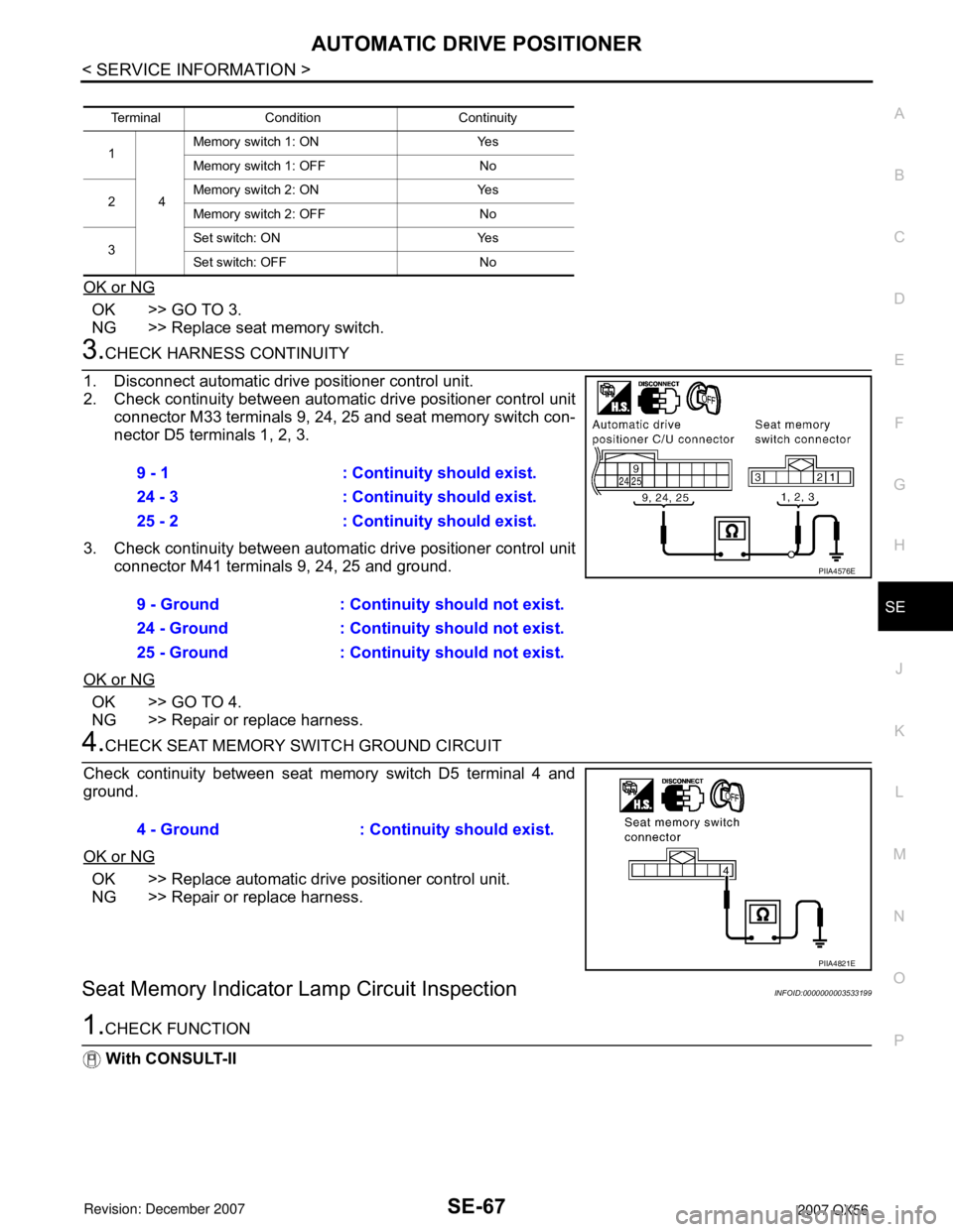
1. Disconnect automatic drive positioner control unit.
2. Check continuity between automatic drive positioner control unit
connector M33 terminals 9, 24, 25 and seat memory switch con-
nector D5 terminals 1, 2, 3.
3. Check continuity between automatic drive positioner control unit
connector M41 terminals 9, 24, 25 and ground.
OK or NG
OK >> GO TO 4.
NG >> Repair or replace harness.
4.CHECK SEAT MEMORY SWITCH GROUND CIRCUIT
Check continuity between seat memory switch D5 terminal 4 and
ground.
OK or NG
OK >> Replace automatic drive positioner control unit.
NG >> Repair or replace harness.
Seat Memory Indicator Lamp Circuit InspectionINFOID:0000000003533199
1.CHECK FUNCTION
With CONSULT-II
Terminal Condition Continuity
1
4Memory switch 1: ON Yes
Memory switch 1: OFF No
2Memory switch 2: ON Yes
Memory switch 2: OFF No
3Set switch: ON Yes
Set switch: OFF No
9 - 1 : Continuity should exist.
24 - 3 : Continuity should exist.
25 - 2 : Continuity should exist.
9 - Ground : Continuity should not exist.
24 - Ground : Continuity should not exist.
25 - Ground : Continuity should not exist.
PIIA4576E
4 - Ground : Continuity should exist.
PIIA4821E
Page 2740 of 3061
SE-68
< SERVICE INFORMATION >
AUTOMATIC DRIVE POSITIONER
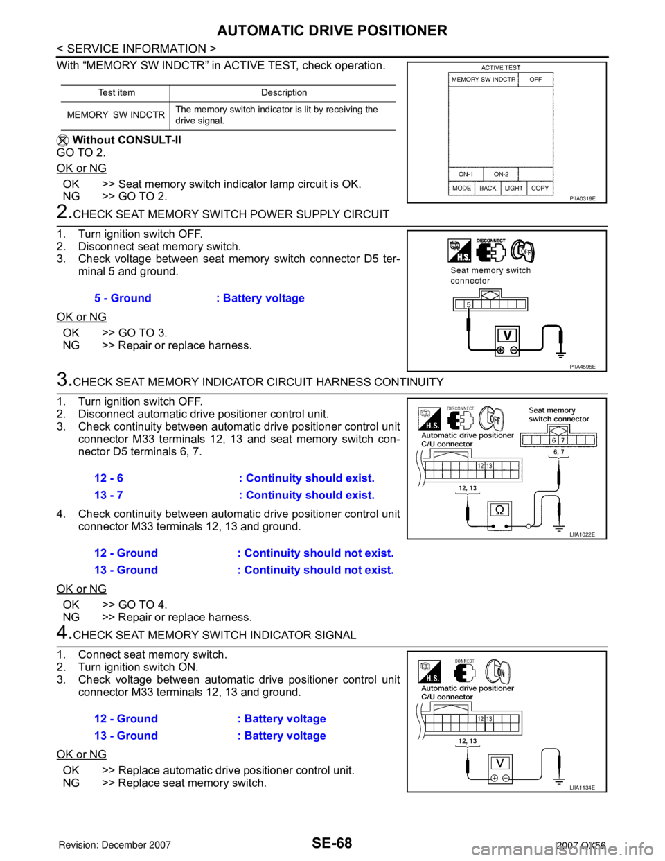
With “MEMORY SW INDCTR” in ACTIVE TEST, check operation.
Without CONSULT-II
GO TO 2.
OK or NG
OK >> Seat memory switch indicator lamp circuit is OK.
NG >> GO TO 2.
2.CHECK SEAT MEMORY SWITCH POWER SUPPLY CIRCUIT
1. Turn ignition switch OFF.
2. Disconnect seat memory switch.
3. Check voltage between seat memory switch connector D5 ter-
minal 5 and ground.
OK or NG
OK >> GO TO 3.
NG >> Repair or replace harness.
3.CHECK SEAT MEMORY INDICATOR CIRCUIT HARNESS CONTINUITY
1. Turn ignition switch OFF.
2. Disconnect automatic drive positioner control unit.
3. Check continuity between automatic drive positioner control unit
connector M33 terminals 12, 13 and seat memory switch con-
nector D5 terminals 6, 7.
4. Check continuity between automatic drive positioner control unit
connector M33 terminals 12, 13 and ground.
OK or NG
OK >> GO TO 4.
NG >> Repair or replace harness.
4.CHECK SEAT MEMORY SWITCH INDICATOR SIGNAL
1. Connect seat memory switch.
2. Turn ignition switch ON.
3. Check voltage between automatic drive positioner control unit
connector M33 terminals 12, 13 and ground.
OK or NG
OK >> Replace automatic drive positioner control unit.
NG >> Replace seat memory switch.
Te s t i t e m D e s c r i p t i o n
MEMORY SW INDCTRThe memory switch indicator is lit by receiving the
drive signal.
PIIA0319E
5 - Ground : Battery voltage
PIIA4595E
12 - 6 : Continuity should exist.
13 - 7 : Continuity should exist.
12 - Ground : Continuity should not exist.
13 - Ground : Continuity should not exist.
LIIA1022E
12 - Ground : Battery voltage
13 - Ground : Battery voltage
LIIA1134E
Page 2776 of 3061
SRS-6
< SERVICE INFORMATION >
SUPPLEMENTAL RESTRAINT SYSTEM (SRS)
Front Seat Belt Pre-tensioner with Load Limiter
INFOID:0000000003532858
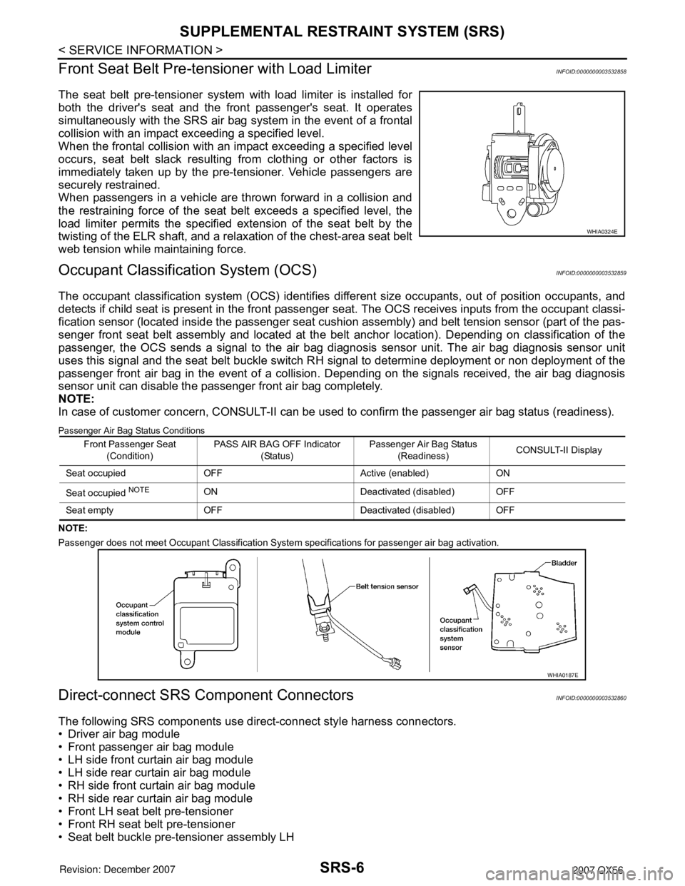
The seat belt pre-tensioner system with load limiter is installed for
both the driver's seat and the front passenger's seat. It operates
simultaneously with the SRS air bag system in the event of a frontal
collision with an impact exceeding a specified level.
When the frontal collision with an impact exceeding a specified level
occurs, seat belt slack resulting from clothing or other factors is
immediately taken up by the pre-tensioner. Vehicle passengers are
securely restrained.
When passengers in a vehicle are thrown forward in a collision and
the restraining force of the seat belt exceeds a specified level, the
load limiter permits the specified extension of the seat belt by the
twisting of the ELR shaft, and a relaxation of the chest-area seat belt
web tension while maintaining force.
Occupant Classification System (OCS)INFOID:0000000003532859
The occupant classification system (OCS) identifies different size occupants, out of position occupants, and
detects if child seat is present in the front passenger seat. The OCS receives inputs from the occupant classi-
fication sensor (located inside the passenger seat cushion assembly) and belt tension sensor (part of the pas-
senger front seat belt assembly and located at the belt anchor location). Depending on classification of the
passenger, the OCS sends a signal to the air bag diagnosis sensor unit. The air bag diagnosis sensor unit
uses this signal and the seat belt buckle switch RH signal to determine deployment or non deployment of the
passenger front air bag in the event of a collision. Depending on the signals received, the air bag diagnosis
sensor unit can disable the passenger front air bag completely.
NOTE:
In case of customer concern, CONSULT-II can be used to confirm the passenger air bag status (readiness).
Passenger Air Bag Status Conditions
NOTE:
Passenger does not meet Occupant Classification System specifications for passenger air bag activation.
Direct-connect SRS Component ConnectorsINFOID:0000000003532860
The following SRS components use direct-connect style harness connectors.
• Driver air bag module
• Front passenger air bag module
• LH side front curtain air bag module
• LH side rear curtain air bag module
• RH side front curtain air bag module
• RH side rear curtain air bag module
• Front LH seat belt pre-tensioner
• Front RH seat belt pre-tensioner
• Seat belt buckle pre-tensioner assembly LH
WHIA0324E
Front Passenger Seat
(Condition)PASS AIR BAG OFF Indicator
(Status)Passenger Air Bag Status
(Readiness)CONSULT-II Display
Seat occupied OFF Active (enabled) ON
Seat occupied
NOTEON Deactivated (disabled) OFF
Seat empty OFF Deactivated (disabled) OFF
WHIA0187E