2007 INFINITI QX56 air suspension
[x] Cancel search: air suspensionPage 1 of 3061

-1
QUICK REFERENCE INDEX
AGENERAL INFORMATIONGIGeneral Information
BENGINEEMEngine Mechanical
LUEngine Lubrication System
COEngine Cooling System
ECEngine Control System
FLFuel System
EXExhaust System
ACCAccelerator Control System
CTRANSMISSION/
TRANSAXLEATAutomatic Transmission
DDRIVELINE/AXLETFTransfer
PRPropeller Shaft
FFDFront Final Drive
RFDRear Final Drive
FAXFront Axle
RAXRear Axle
ESUSPENSIONFSUFront Suspension
RSURear Suspension
WTRoad Wheels & Tires
FBRAKESBRBrake System
PBParking Brake System
BRCBrake Control System
GSTEERINGPSPower Steering System
HRESTRAINTSSBSeat Belts
SRSSupplemental Restraint System (SRS)
IBODYBLBody, Lock & Security System
GWGlasses, Window System & Mirrors
RFRoof
EIExterior & Interior
IPInstrument Panel
SESeat
APAdjustable Pedal
JAIR CONDITIONERATCAutomatic Air Conditioner
KELECTRICALSCStarting & Charging System
LTLighting System
DIDriver Information System
WWWiper, Washer & Horn
BCSBody Control System
LANLAN System
AVAudio Visual, Navigation & Telephone System
ACSAuto Cruise Control System
PGPower Supply, Ground & Circuit Elements
LMAINTENANCEMAMaintenance
Edition: August 2006
Revision: December 2007
Publication No. SM7E-1J60U1
B
D
© 2007 NISSAN NORTH AMERICA, INC.
All rights reserved. No part of this Service Manual may be reproduced or stored in a retrieval system, or transmitted in any
form, or by any means, electronic, mechanical, photo-copying, recording or otherwise, without the prior written permission
of Nissan North America, Inc.
A
C
E
F
G
H
I
J
K
L
M
Page 25 of 3061
![INFINITI QX56 2007 Factory Service Manual ACS-12
< SERVICE INFORMATION >[ICC]
LASER BEAM AIMING ADJUSTMENT
LASER BEAM AIMING ADJUSTMENT
Outline of Laser Beam Aiming Adjustment ProcedureINFOID:0000000003533782
CAUTION:
• The laser beam aimin INFINITI QX56 2007 Factory Service Manual ACS-12
< SERVICE INFORMATION >[ICC]
LASER BEAM AIMING ADJUSTMENT
LASER BEAM AIMING ADJUSTMENT
Outline of Laser Beam Aiming Adjustment ProcedureINFOID:0000000003533782
CAUTION:
• The laser beam aimin](/manual-img/42/57029/w960_57029-24.png)
ACS-12
< SERVICE INFORMATION >[ICC]
LASER BEAM AIMING ADJUSTMENT
LASER BEAM AIMING ADJUSTMENT
Outline of Laser Beam Aiming Adjustment ProcedureINFOID:0000000003533782
CAUTION:
• The laser beam aiming adjustment cannot be performed without CONSULT-II.
• The laser beam aiming adjustment must be performed every time the ICC sensor is removed,
installed or has been moved as a result of a collision.
1. Prepare the vehicle and the work area.
2. Set up the ICC target board. For details, refer to Technical Service Bulletin.
3. Adjust the sensor following the procedure on CONSULT-II.
4. Check system operation after the adjustment.
PreparationINFOID:0000000003533783
• Place the vehicle on level ground. Shift the transmission into "P" position and release the parking brake.
• Adjust the tire pressure to the specified value.
• See that there is no load in the vehicle. Coolant, engine oil and fuel should be filled to correct level.
• Check that the vehicle suspension has been adjusted to the standard height by the load leveling rear air sus-
pension system. Refer to RSU-10, "
Basic Inspection" .
• Clean the sensor with a soft cloth.
Setting up the ICC Target BoardINFOID:0000000003533784
CAUTION:
Accuracy in setting up the ICC target board is essential for the laser beam aiming adjustment. For
details, refer to Technical Service Bulletin.
ADJUSTING HEIGHT OF THE TARGET
1. Attach a triangle scale as shown.Tool number : KV99110100 (J-45718)
LKIA0632E
WKIA1849E
Page 853 of 3061

BL-142
< SERVICE INFORMATION >
BODY REPAIR
6. 2nd crossmember assembly
7. Front upper link mounting bracket RH/LH
8. Panhard rod bracket reinforcement
9. Bound bumper bracket RH/LH
10. Front brake hose bracket RH/LH
11. Panhard rod reinforcement
12. 4th crossmember gusset RH/LH
13. 2nd cab mounting bracket RH/LH
14. 3rd cab mounting bracket RH/LH
15. 4th cab mounting reinforcement RH/LH
16. 4th cab mounting bracket RH/LH
17. Rear suspension mounting bracket RH/LH
18. Rear brake hose bracket
19. Rear shock absorber bracket assembly RH/LH
20. Rear bound bumper bracket RH/LH
21. Rear bracket bumper reinforcement RH/LH
22. Cab mounting bracket assembly RH/LH
23. 9th crossmember assembly
24. Exhaust bracket assembly
25. Canister bracket, LH
26. 7th crossmember reinforcement
27. 7th crossmember assembly
28. 6th crossmember assembly
29. 4th crossmember gusset RH/LH
30. 4th crossmember assembly
31. 3rd crossmember assembly
32. Frame assembly
Corrosion ProtectionINFOID:0000000003533007
DESCRIPTION
To provide improved corrosion prevention, the following anti-corrosive measures have been implemented in
NISSAN production plants. When repairing or replacing body panels, it is necessary to use the same anti-cor-
rosive measures.
ANTI-CORROSIVE PRECOATED STEEL (GALVANNEALED STEEL)
To improve repairability and corrosion resistance, a new type of anti-
corrosive precoated steel sheet has been adopted replacing conven-
tional zinc-coated steel sheet.
Galvannealed steel is electroplated and heated to form Zinc-iron
alloy, which provides excellent and long term corrosion resistance
with cationic electrode position primer.
Nissan Genuine Service Parts are fabricated from galvannealed steel. Therefore, it is recommended that
GENUINE NISSAN PARTS or equivalent be used for panel replacement to maintain the anti-corrosive perfor-
mance built into the vehicle at the factory.
PHOSPHATE COATING TREATMENT AND CATIONIC ELECTRODEPOSITION PRIMER
PIIA0093E
Page 902 of 3061

BR-4
< SERVICE INFORMATION >
NOISE, VIBRATION AND HARSHNESS (NVH) TROUBLESHOOTING
NOISE, VIBRATION AND HARSHNESS (NVH) TROUBLESHOOTING
NVH Troubleshooting ChartINFOID:0000000003532721
Use the chart below to help you find the cause of the symptom. If necessary, repair or replace these parts.
×: ApplicableReference page
BR-18
, BR-24
BR-18
, BR-24
BR-18
, BR-24
BR-20
, BR-26
BR-20
, BR-26
BR-20
, BR-26
BR-20
, BR-26
BR-20
, BR-26
BR-20
, BR-26
BR-20
, BR-26
PR-3, "
NVH Troubleshooting Chart
"
FFD-6, "
NVH Troubleshooting Chart
", RFD-7, "
NVH Troubleshooting Chart
"
FAX-4, "
NVH Troubleshooting Chart
", RAX-4, "
NVH Troubleshooting Chart
"
FSU-4, "
NVH Troubleshooting Chart
", RSU-4, "
NVH Troubleshooting Chart
"
WT-4, "
NVH Troubleshooting Chart
"
PS-5, "
NVH Troubleshooting Chart
"
Possible cause and
SUSPECTED PARTS
Pads - damaged
Pads - uneven wear
Shims damaged
Rotor imbalance
Rotor damage
Rotor runout
Rotor deformation
Rotor deflection
Rotor rust
Rotor thickness variation
PROPELLER SHAFT
DIFFERENTIAL
DRIVESHAFT
SUSPENSION
TIRES AND ROAD WHEEL
STEERING
SymptomNoise××× ××××××
Shake××××××
Shimmy, Shudder××××××× ××××
Page 1179 of 3061

EC-96
< SERVICE INFORMATION >
TROUBLE DIAGNOSIS
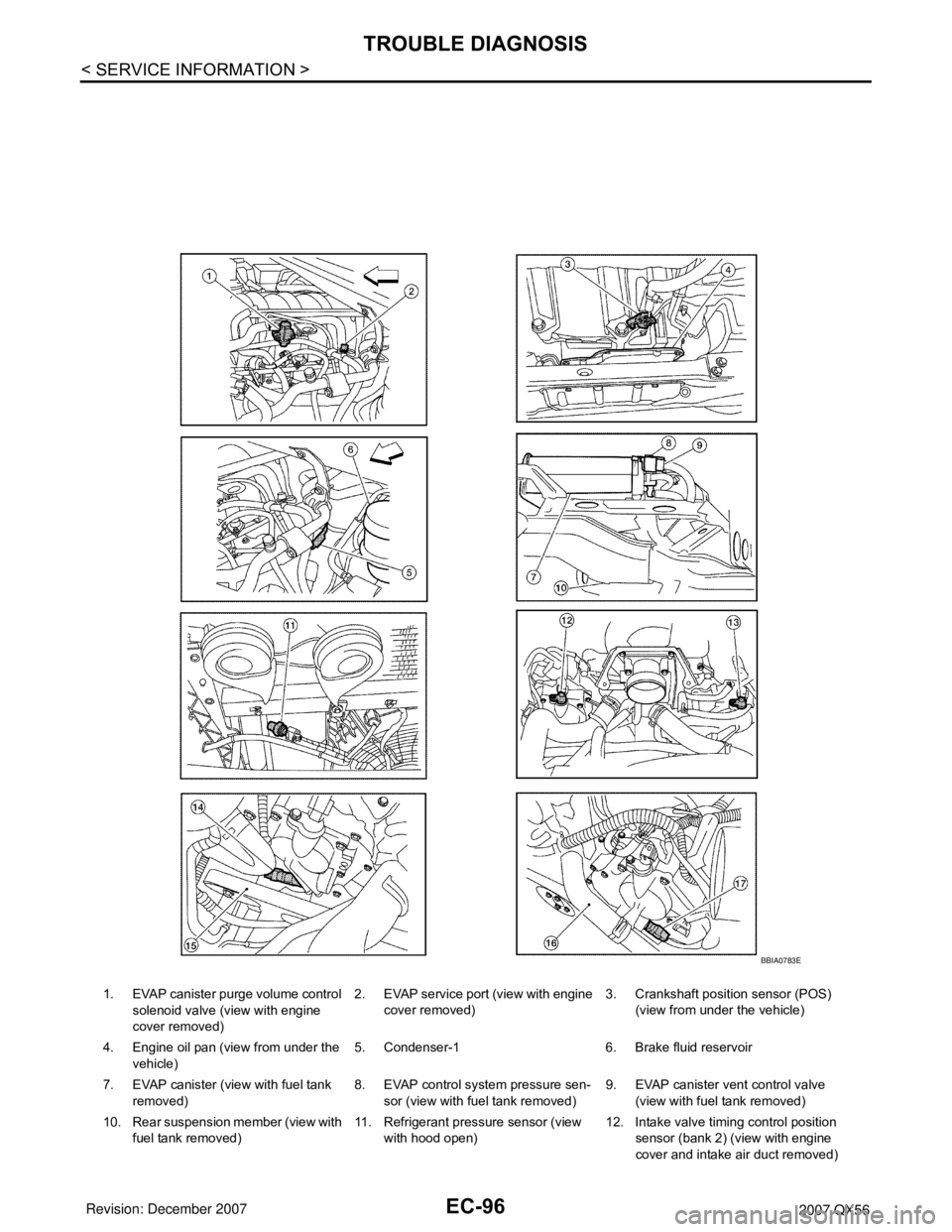
1. EVAP canister purge volume control
solenoid valve (view with engine
cover removed)2. EVAP service port (view with engine
cover removed)3. Crankshaft position sensor (POS)
(view from under the vehicle)
4. Engine oil pan (view from under the
vehicle)5. Condenser-1 6. Brake fluid reservoir
7. EVAP canister (view with fuel tank
removed)8. EVAP control system pressure sen-
sor (view with fuel tank removed)9. EVAP canister vent control valve
(view with fuel tank removed)
10. Rear suspension member (view with
fuel tank removed)11. Refrigerant pressure sensor (view
with hood open)12. Intake valve timing control position
sensor (bank 2) (view with engine
cover and intake air duct removed)
BBIA0783E
Page 1890 of 3061

FAX-4
< SERVICE INFORMATION >
NOISE, VIBRATION AND HARSHNESS (NVH) TROUBLESHOOTING
NOISE, VIBRATION AND HARSHNESS (NVH) TROUBLESHOOTING
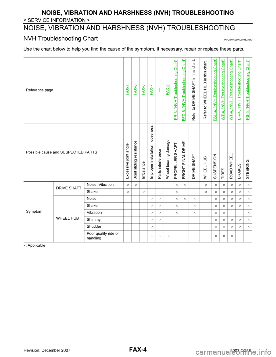
NVH Troubleshooting ChartINFOID:0000000003532613
Use the chart below to help you find the cause of the symptom. If necessary, repair or replace these parts.
×: ApplicableReference page
FAX-7FAX-8FAX-8FAX-7—
FAX-5
PR-3, "
NVH Troubleshooting Chart
"
FFD-6, "
NVH Troubleshooting Chart
"
Refer to DRIVE SHAFT in this chart.
Refer to WHEEL HUB in this chart.
FSU-4, "
NVH Troubleshooting Chart
"
WT-4, "
NVH Troubleshooting Chart
"
WT-4, "
NVH Troubleshooting Chart
"
BR-4, "
NVH Troubleshooting Chart
"
PS-5, "
NVH Troubleshooting Chart
"
Possible cause and SUSPECTED PARTS
Excessive joint angle
Joint sliding resistance
Imbalance
Improper installation, looseness
Parts interference
Wheel bearing damage
PROPELLER SHAFT
FRONT FINAL DRIVE
DRIVE SHAFT
WHEEL HUB
SUSPENSION
TIRES
ROAD WHEEL
BRAKES
STEERING
SymptomDRIVE SHAFTNoise, Vibration×× ×× × ×××× ×
Shake× × × × ×××× ×
WHEEL HUBNoise×× ×× × ×××× ×
Shake×× × × ×××× ×
Vibration×× × × ×× ×
Shimmy×× ×××× ×
Shudder× ×××× ×
Poor quality ride or
handling××× ×××
Page 1905 of 3061

FFD-6
< SERVICE INFORMATION >
NOISE, VIBRATION AND HARSHNESS (NVH) TROUBLESHOOTING
NOISE, VIBRATION AND HARSHNESS (NVH) TROUBLESHOOTING
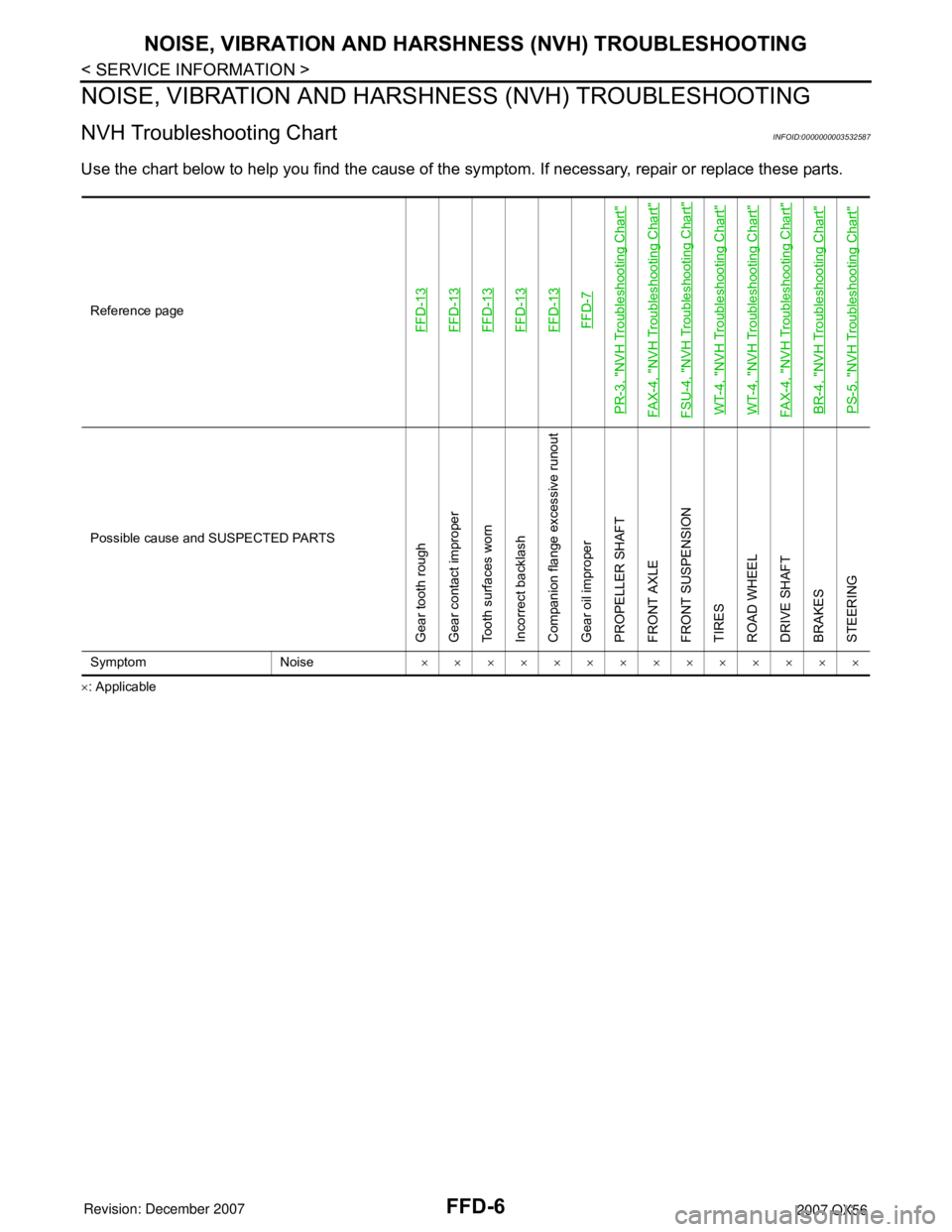
NVH Troubleshooting ChartINFOID:0000000003532587
Use the chart below to help you find the cause of the symptom. If necessary, repair or replace these parts.
×: ApplicableReference page
FFD-13FFD-13FFD-13FFD-13FFD-13FFD-7
PR-3, "
NVH Troubleshooting Chart
"
FAX-4, "
NVH Troubleshooting Chart
"
FSU-4, "
NVH Troubleshooting Chart
"
WT-4, "
NVH Troubleshooting Chart
"
WT-4, "
NVH Troubleshooting Chart
"
FAX-4, "
NVH Troubleshooting Chart
"
BR-4, "
NVH Troubleshooting Chart
"
PS-5, "
NVH Troubleshooting Chart
"
Possible cause and SUSPECTED PARTS
Gear tooth rough
Gear contact improper
Tooth surfaces worn
Incorrect backlash
Companion flange excessive runout
Gear oil improper
PROPELLER SHAFT
FRONT AXLE
FRONT SUSPENSION
TIRES
ROAD WHEEL
DRIVE SHAFT
BRAKES
STEERING
Symptom Noise××××××××××××××
Page 1950 of 3061

FSU-4
< SERVICE INFORMATION >
NOISE, VIBRATION AND HARSHNESS (NVH) TROUBLESHOOTING
NOISE, VIBRATION AND HARSHNESS (NVH) TROUBLESHOOTING
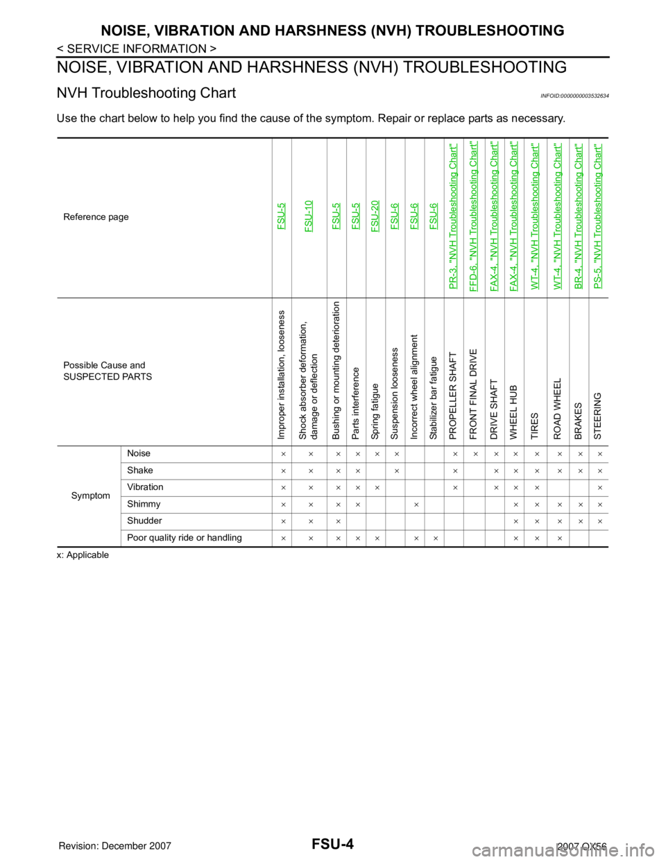
NVH Troubleshooting ChartINFOID:0000000003532634
Use the chart below to help you find the cause of the symptom. Repair or replace parts as necessary.
x: ApplicableReference page
FSU-5FSU-10FSU-5FSU-5FSU-20FSU-6FSU-6FSU-6
PR-3, "
NVH Troubleshooting Chart
"
FFD-6, "
NVH Troubleshooting Chart
"
FAX-4, "
NVH Troubleshooting Chart
"
FAX-4, "
NVH Troubleshooting Chart
"
WT-4, "
NVH Troubleshooting Chart
"
WT-4, "
NVH Troubleshooting Chart
"
BR-4, "
NVH Troubleshooting Chart
"
PS-5, "
NVH Troubleshooting Chart
"
Possible Cause and
SUSPECTED PARTS
Improper installation, looseness
Shock absorber deformation,
damage or deflection
Bushing or mounting deterioration
Parts interference
Spring fatigue
Suspension looseness
Incorrect wheel alignment
Stabilizer bar fatigue
PROPELLER SHAFT
FRONT FINAL DRIVE
DRIVE SHAFT
WHEEL HUB
TIRES
ROAD WHEEL
BRAKES
STEERING
SymptomNoise× × ×××× × × ×× × × ××
Shake× × ×× × × ×× × × ××
Vibration× × ××× × ×× × ×
Shimmy× × ×× × × × × ××
Shudder××× ×××××
Poor quality ride or handling××××× ×× ×××