Page 2609 of 3061

TROUBLE DIAGNOSES FOR SYMPTOMS
RSU-19
< SERVICE INFORMATION >
C
D
F
G
H
I
J
K
L
MA
B
RSU
N
O
P
TROUBLE DIAGNOSES FOR SYMPTOMS
Load Leveling Rear Air Suspension System Does Not OperateINFOID:0000000003532667
1.CHECK WARNING LAMP ACTIVATION
Make sure warning lamp remains off while driving.
OK or NG
OK >> GO TO 2.
NG >> Carry out self-diagnosis. Refer to RSU-11, "
CONSULT-II Function (AIR LEVELIZER)" .
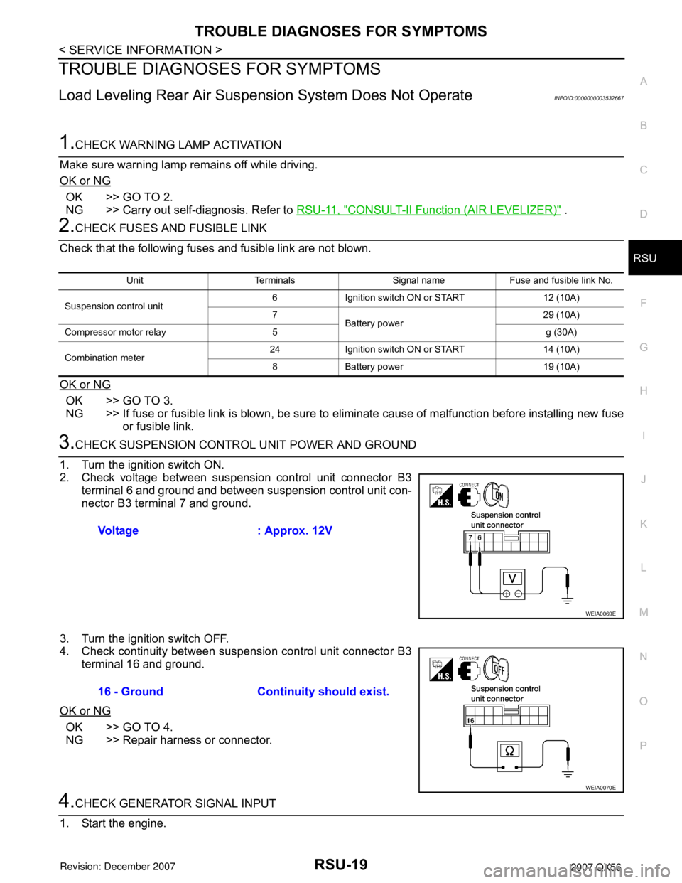
2.CHECK FUSES AND FUSIBLE LINK
Check that the following fuses and fusible link are not blown.
OK or NG
OK >> GO TO 3.
NG >> If fuse or fusible link is blown, be sure to eliminate cause of malfunction before installing new fuse
or fusible link.
3.CHECK SUSPENSION CONTROL UNIT POWER AND GROUND
1. Turn the ignition switch ON.
2. Check voltage between suspension control unit connector B3
terminal 6 and ground and between suspension control unit con-
nector B3 terminal 7 and ground.
3. Turn the ignition switch OFF.
4. Check continuity between suspension control unit connector B3
terminal 16 and ground.
OK or NG
OK >> GO TO 4.
NG >> Repair harness or connector.
4.CHECK GENERATOR SIGNAL INPUT
1. Start the engine.
Unit Terminals Signal name Fuse and fusible link No.
Suspension control unit6 Ignition switch ON or START 12 (10A)
7
Battery power29 (10A)
Compressor motor relay 5 g (30A)
Combination meter24 Ignition switch ON or START 14 (10A)
8 Battery power 19 (10A)
Voltage : Approx. 12V
WEIA0069E
16 - Ground Continuity should exist.
WEIA0070E
Page 2610 of 3061
RSU-20
< SERVICE INFORMATION >
TROUBLE DIAGNOSES FOR SYMPTOMS
2. Check voltage between suspension control unit connector B3
terminal 15 and ground.
OK or NG
OK >> Replace the suspension control unit. Refer to RSU-42.
NG >> Repair the circuit.
Chek Suspension Indicator Lamp Stays On When Ignition Switch Is Turned On
INFOID:0000000003532668
1.CARRY OUT SELF-DIAGNOSIS
Carry out self-diagnosis. Refer to RSU-11, "
CONSULT-II Function (AIR LEVELIZER)".
Are malfunctions detected in self-diagnosis?
YES >> Refer to RSU-11, "CONSULT-II Function (AIR LEVELIZER)" .
NO >> Refer to DI-26
. Voltage : Approx. 12V
WEIA0071E
Page 2612 of 3061
RSU-22
< SERVICE INFORMATION >
REAR SUSPENSION ASSEMBLY
Rear Load Leveling Air Suspension System
On-Vehicle Inspection and ServiceINFOID:0000000003532670
Check all of the component mountings for any excessive looseness, or back lash. Check the components for
any excessive wear, damage, or abnormal conditions. Repair or replace the components as necessary.
SHOCK ABSORBER INSPECTION
• Check the shock absorbers for any air leaks or damage, and replace as necessary.
• Check the hoses for any air leaks or damage, and replace as necessary.
10. Shock absorber 11. Suspension arm 12. Lower rubber seat
13. Coil spring 14. Upper rubber seat 15. Rear suspension member
16. Spare tire bracket 17. Bound bumper
AWEIA0076ZZ
1. Rear load leveling air suspension
hose, RH2. Shock absorber, RH 3. Height sensor
4. Rear load leveling air suspension
hose, LH5. Shock absorber, LH 6. Rear load leveling air suspension
compressor assembly
⇐Front
Page 2613 of 3061

REAR SUSPENSION ASSEMBLY
RSU-23
< SERVICE INFORMATION >
C
D
F
G
H
I
J
K
L
MA
B
RSU
N
O
P
Wheel AlignmentInspectionINFOID:0000000003532671
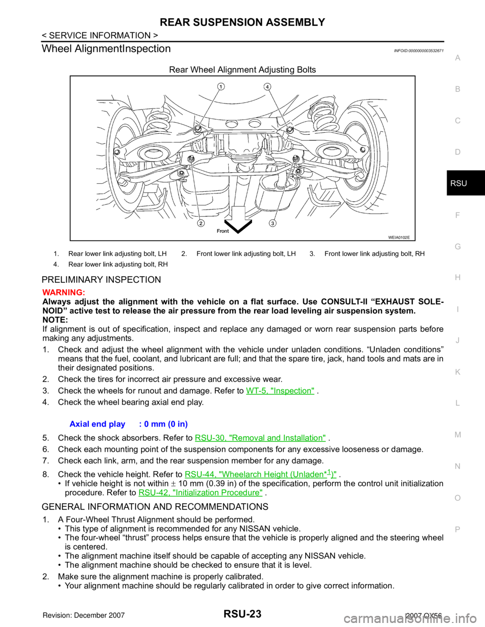
Rear Wheel Alignment Adjusting Bolts
PRELIMINARY INSPECTION
WARNING:
Always adjust the alignment with the vehicle on a flat surface. Use CONSULT-II “EXHAUST SOLE-
NOID” active test to release the air pressure from the rear load leveling air suspension system.
NOTE:
If alignment is out of specification, inspect and replace any damaged or worn rear suspension parts before
making any adjustments.
1. Check and adjust the wheel alignment with the vehicle under unladen conditions. “Unladen conditions”
means that the fuel, coolant, and lubricant are full; and that the spare tire, jack, hand tools and mats are in
their designated positions.
2. Check the tires for incorrect air pressure and excessive wear.
3. Check the wheels for runout and damage. Refer to WT-5, "
Inspection" .
4. Check the wheel bearing axial end play.
5. Check the shock absorbers. Refer to RSU-30, "
Removal and Installation" .
6. Check each mounting point of the suspension components for any excessive looseness or damage.
7. Check each link, arm, and the rear suspension member for any damage.
8. Check the vehicle height. Refer to RSU-44, "
Wheelarch Height (Unladen*1)" .
• If vehicle height is not within ± 10 mm (0.39 in) of the specification, perform the control unit initialization
procedure. Refer to RSU-42, "
Initialization Procedure" .
GENERAL INFORMATION AND RECOMMENDATIONS
1. A Four-Wheel Thrust Alignment should be performed.
• This type of alignment is recommended for any NISSAN vehicle.
• The four-wheel “thrust” process helps ensure that the vehicle is properly aligned and the steering wheel
is centered.
• The alignment machine itself should be capable of accepting any NISSAN vehicle.
• The alignment machine should be checked to ensure that it is level.
2. Make sure the alignment machine is properly calibrated.
• Your alignment machine should be regularly calibrated in order to give correct information.
WEIA0102E
1. Rear lower link adjusting bolt, LH 2. Front lower link adjusting bolt, LH 3. Front lower link adjusting bolt, RH
4. Rear lower link adjusting bolt, RH
Axial end play : 0 mm (0 in)
Page 2617 of 3061

REAR SUSPENSION MEMBER
RSU-27
< SERVICE INFORMATION >
C
D
F
G
H
I
J
K
L
MA
B
RSU
N
O
P
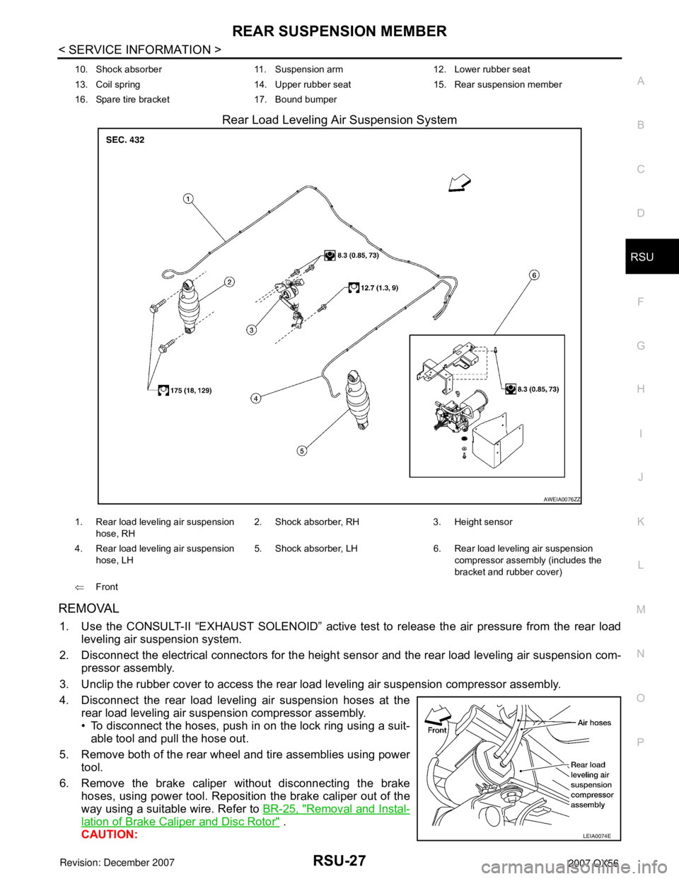
Rear Load Leveling Air Suspension System
REMOVAL
1. Use the CONSULT-II “EXHAUST SOLENOID” active test to release the air pressure from the rear load
leveling air suspension system.
2. Disconnect the electrical connectors for the height sensor and the rear load leveling air suspension com-
pressor assembly.
3. Unclip the rubber cover to access the rear load leveling air suspension compressor assembly.
4. Disconnect the rear load leveling air suspension hoses at the
rear load leveling air suspension compressor assembly.
• To disconnect the hoses, push in on the lock ring using a suit-
able tool and pull the hose out.
5. Remove both of the rear wheel and tire assemblies using power
tool.
6. Remove the brake caliper without disconnecting the brake
hoses, using power tool. Reposition the brake caliper out of the
way using a suitable wire. Refer to BR-25, "
Removal and Instal-
lation of Brake Caliper and Disc Rotor" .
CAUTION:
10. Shock absorber 11. Suspension arm 12. Lower rubber seat
13. Coil spring 14. Upper rubber seat 15. Rear suspension member
16. Spare tire bracket 17. Bound bumper
AWEIA0076ZZ
1. Rear load leveling air suspension
hose, RH2. Shock absorber, RH 3. Height sensor
4. Rear load leveling air suspension
hose, LH5. Shock absorber, LH 6. Rear load leveling air suspension
compressor assembly (includes the
bracket and rubber cover)
⇐Front
LEIA0074E
Page 2618 of 3061

RSU-28
< SERVICE INFORMATION >
REAR SUSPENSION MEMBER
• Do not crimp or stretch the brake hose when repositioning the brake caliper out of the way.
• Do not press brake pedal while the brake caliper is removed.
7. Remove the spare tire.
8. Disconnect the two rear ABS sensor electrical connectors.
9. Remove the two rear drive shafts. Refer to RAX-7, "
Removal and Installation" .
10. Remove the rear final drive. Refer to RFD-14
.
11. Remove the EVAP canister bolt from the top of the rear suspension member.
12. Disconnect the parking brake cables from the brackets on the rear suspension member.
13. Set a suitable jack to support each of the rear lower links and the
coil spring tension.
14. Remove both of the rear lower link outer bolts and lower the jack to remove the rear coil springs.
15. Remove the two bolts to disconnect the seat belt latch anchor
from the rear suspension member.
16. Disconnect both of the connecting rods from the rear stabilizer
bar.
17. Set a suitable jack under the rear suspension member.
18. Remove the six rear suspension member bolts.
19. Slowly lower the jack to remove the rear suspension member,
suspension arm, front and rear lower links and stabilizer bar as
an assembly.
20. If necessary, remove the suspension arm, spare tire bracket,
height sensor, rear load leveling air suspension hoses, stabilizer
bar, knuckle, and front and rear lower links from the rear suspension member.
INSPECTION AFTER REMOVAL
Check the rear suspension member for deformation, cracks, and other damage and replace if necessary.
INSTALLATION
Installation is in the reverse order of removal.
• When raising the rear suspension member assembly, use the
locating pins to align the rear suspension member to the vehicle
body.
LEIA0077E
LEIA0075E
LEIA0083E
Page 2619 of 3061
REAR SUSPENSION MEMBER
RSU-29
< SERVICE INFORMATION >
C
D
F
G
H
I
J
K
L
MA
B
RSU
N
O
P
• When installing the upper and lower rubber seats for the rear coil
springs, the arrow embossed on the rubber seats must point out
toward the wheel and tire assembly.
• To connect the rear load leveling air suspension hoses, the lock
ring must be fully seated in the fitting. Insert the hose “B” into the
lock ring “A” until the lock ring “A” is touching the hose “B” as
shown. Pull on the hose to check that it is securely inserted.
• Perform the final tightening of the nuts and bolts for the links (rubber bushing) under unladen condition
(unladen condition means that the fuel tank, engine coolant and lubricants are at the full specification, and
the spare tire, jack, hand tools, and mats are in their designated positions) with the tires on level ground.
• Check the wheel alignment. Refer to FSU-19, "
Wheel Alignment (Unladen*1) *6" .
LEIA0076E
LEIA0078E
Page 2620 of 3061

RSU-30
< SERVICE INFORMATION >
SHOCK ABSORBER
SHOCK ABSORBER
Removal and InstallationINFOID:0000000003532673
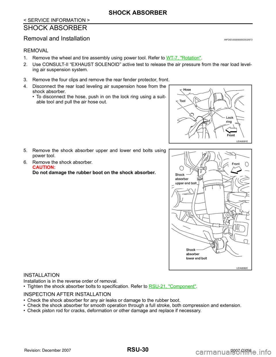
REMOVAL
1. Remove the wheel and tire assembly using power tool. Refer to WT-7, "Rotation".
2. Use CONSULT-II “EXHAUST SOLENOID” active test to release the air pressure from the rear load level-
ing air suspension system.
3. Remove the four clips and remove the rear fender protector, front.
4. Disconnect the rear load leveling air suspension hose from the
shock absorber.
• To disconnect the hose, push in on the lock ring using a suit-
able tool and pull the air hose out.
5. Remove the shock absorber upper and lower end bolts using
power tool.
6. Remove the shock absorber.
CAUTION:
Do not damage the rubber boot on the shock absorber.
INSTALLATION
Installation is in the reverse order of removal.
• Tighten the shock absorber bolts to specification. Refer to RSU-21, "
Component".
INSPECTION AFTER INSTALLATION
• Check the shock absorber for any air leaks or damage to the rubber boot.
• Check the shock absorber for smooth operation through a full stroke, both compression and extension.
• Check piston rod for cracks, deformation or other damage and replace if necessary.
LEIA0081E
LEIA0082E