2007 INFINITI QX56 service schedule
[x] Cancel search: service schedulePage 153 of 3061

TROUBLE DIAGNOSIS
AT-83
< SERVICE INFORMATION >
D
E
F
G
H
I
J
K
L
MA
B
AT
N
O
PCONSULT-II Function (A/T)INFOID:0000000003532259
CONSULT-II can display each diagnostic item using the diagnostic test modes shown following.
CONSULT-II REFERENCE VALUE
NOTICE:
1. The CONSULT-II electrically displays shift timing and lock-up timing (that is, operation timing of each sole-
noid).
Check for time difference between actual shift timing and the CONSULT-II display. If the difference is
noticeable, mechanical parts (except solenoids, sensors, etc.) may be malfunctioning. Check mechanical
parts using applicable diagnostic procedures.
2. Shift schedule (which implies gear position) displayed on CONSULT-II and that indicated in Service Man-
ual may differ slightly. This occurs because of the following reasons:
- Actual shift schedule has more or less tolerance or allowance,
- Shift schedule indicated in Service Manual refers to the point where shifts start, and
- Gear position displayed on CONSULT-II indicates the point where shifts are completed.
3. Display of solenoid valves on CONSULT-II changes at the start of shifting, while gear position is displayed
upon completion of shifting (which is computed by TCM).
9 B/R Starter relaySelector lever in “N”,“ P” positions. Battery voltage
Selector lever in other positions. 0V
10 B Ground Always 0V Te r m i n a l
No.Wire
colorItem Condition Data (Pyrex.)
TCM diagnostic mode Description
WORK SUPPORTSupports inspections and adjustments. Commands are transmitted to the TCM for setting the status
suitable for required operation, input/output signals are received from the TCM and received data is
displayed.
SELF-DIAG RESULTS Displays TCM self-diagnosis results.
DATA MONITOR Displays TCM input/output data in real time.
CAN DIAG SUPPORT MNTR The result of transmit/receive diagnosis of CAN communication can be read.
ACTIVE TEST Operation of electrical loads can be checked by sending drive signal to them.
FUNCTION TEST Conducted by CONSULT-II instead of a technician to determine whether each system is “OK” or “NG”.
ECU PART NUMBER TCM part number can be read.
Item name Condition Display value (Approx.)
ATF TEMP SE 1
0°C (32° F) - 20°C (68°F) - 80°C (176°F)3.3 - 2.7 - 0.9 V
ATF TEMP SE 23.3 - 2.5 - 0.7 V
TCC SOLENOIDWhen perform slip lock-up 0.2 - 0.4 A
When perform lock-up 0.4 - 0.6 A
SLCT LVR POSISelector lever in “N”,“P” position. N/P
Selector lever in “R” position. R
Selector lever in “D” position. D
Selector lever in “4” position. 4
Selector lever in “3” position. 3
Selector lever in “2” position. 2
Selector lever in “1” position. 1
VHCL/S SE·A/T During drivingApproximately matches the
speedometer reading.
ENGINE SPEED Engine runningClosely matches the tachometer
reading.
Page 183 of 3061

DTC P0744 A/T TCC S/V FUNCTION (LOCK-UP)
AT-113
< SERVICE INFORMATION >
D
E
F
G
H
I
J
K
L
MA
B
AT
N
O
P
DTC P0744 A/T TCC S/V FUNCTION (LOCK-UP)
DescriptionINFOID:0000000003532310
This malfunction is detected when the A/T does not shift into 5th gear position or the torque converter clutch
does not lock-up as instructed by the TCM. This is not only caused by electrical malfunction (circuits open or
shorted) but also by mechanical malfunction such as control valve sticking, improper solenoid valve operation,
etc.
CONSULT-II Reference Value in Data Monitor ModeINFOID:0000000003532311
On Board Diagnosis LogicINFOID:0000000003532312
• This is an OBD-II self-diagnostic item.
• Diagnostic trouble code “P0744 A/T TCC S/V FNCTN” with CONSULT-II is detected under the following con-
ditions.
- When A/T cannot perform lock-up even if electrical circuit is good.
- When TCM detects as irregular by comparing difference value with slip rotation.
Possible CauseINFOID:0000000003532313
• Harness or connectors
(The solenoid circuit is open or shorted.)
• Torque converter clutch solenoid valve
• Hydraulic control circuit
DTC Confirmation ProcedureINFOID:0000000003532314
CAUTION:
Always drive vehicle at a safe speed.
NOTE:
If “DTC Confirmation Procedure” has been previously performed, always turn ignition switch “OFF”
and wait at least 10 seconds before performing the next test.
After the repair, perform the following procedure to confirm the malfunction is eliminated.
WITH CONSULT-II
1. Start engine and Select “TCC S/V FNCTN CHECK” of “DTC
WORK SUPPORT” mode for “A/T” with CONSULT-II and touch
“START”.
2. Accelerate vehicle to more than 80 km/h (50 MPH) and maintain
the following condition continuously until “TESTING” has turned
to “COMPLETE”. (It will take approximately 30 seconds after
“TESTING” shows.)
ACCELE POSI: More than 1.0/8 (at all times during step 4)
TCC SOLENOID: 0.4 - 0.6 A
Selector lever: “D” position
[Reference speed: Constant speed of more than 80 km/h (50
MPH)]
-Make sure “GEAR” shows “5”.
-For shift schedule, refer to AT-299, "
Vehicle Speed When Performing and Releasing Complete
Lock-up".
-If “TESTING” does not appear on CONSULT-II for a long time, select “SELF-DIAG RESULTS”. In
case a 1st trip DTC other than P0744 is shown, refer to applicable “TROUBLE DIAGNOSIS FOR
DTC”.
3. Make sure that “OK” is displayed. (If “NG” is displayed, refer to “DIAGNOSTIC PROCEDURE”.)
Refer to AT-114, "
Diagnosis Procedure".
Item name Condition Display value (Approx.)
TCC SOLENOIDWhen performing slip lock-up 0.2 - 0.4 A
When performing lock-up 0.4 - 0.6 A
BCIA0031E
Page 184 of 3061

AT-114
< SERVICE INFORMATION >
DTC P0744 A/T TCC S/V FUNCTION (LOCK-UP)
Refer to shift schedule, AT-299, "Vehicle Speed When Performing and Releasing Complete Lock-up".
WITH GST
Follow the procedure “With CONSULT-II”.
Diagnosis ProcedureINFOID:0000000003532315
1.CHECK INPUT SIGNAL
With CONSULT-II
1. Turn ignition switch “ON”.
2. Select “MAIN SIGNALS” in “DATA MONITOR” mode for “A/T”
with CONSULT-II.
3. Start the engine.
4. Read out the value of “TCC SOLENOID” while driving.
OK or NG
OK >> GO TO 4.
NG >> GO TO 2.
2.CHECK TCM POWER SUPPLY AND GROUND CIRCUIT
Check TCM power supply and ground circuit. Refer to AT-158
.
OK or NG
OK >> GO TO 3.
NG >> Repair or replace damaged parts.
3.DETECT MALFUNCTIONING ITEM
Check the following items:
• The A/T assembly harness connector pin terminals for damage or loose connection with harness connector.
OK or NG
OK >> Replace the control valve with TCM. Refer to AT-210, "Control Valve with TCM and A/T Fluid Tem-
perature Sensor 2".
NG >> Repair or replace damaged parts.
4.CHECK DTC
Perform “DTC Confirmation Procedure”.
• Refer to AT-113, "
DTC Confirmation Procedure".
OK or NG
OK >>INSPECTION END
NG >> GO TO 2.
Item name Condition Display value (Approx.)
TCC SOLENOIDWhen performing slip lock-up 0.2 - 0.4 A
When performing lock-up 0.4 - 0.6 A
SCIA4793E
Page 1137 of 3061

EC-54
< SERVICE INFORMATION >
ON BOARD DIAGNOSTIC (OBD) SYSTEM
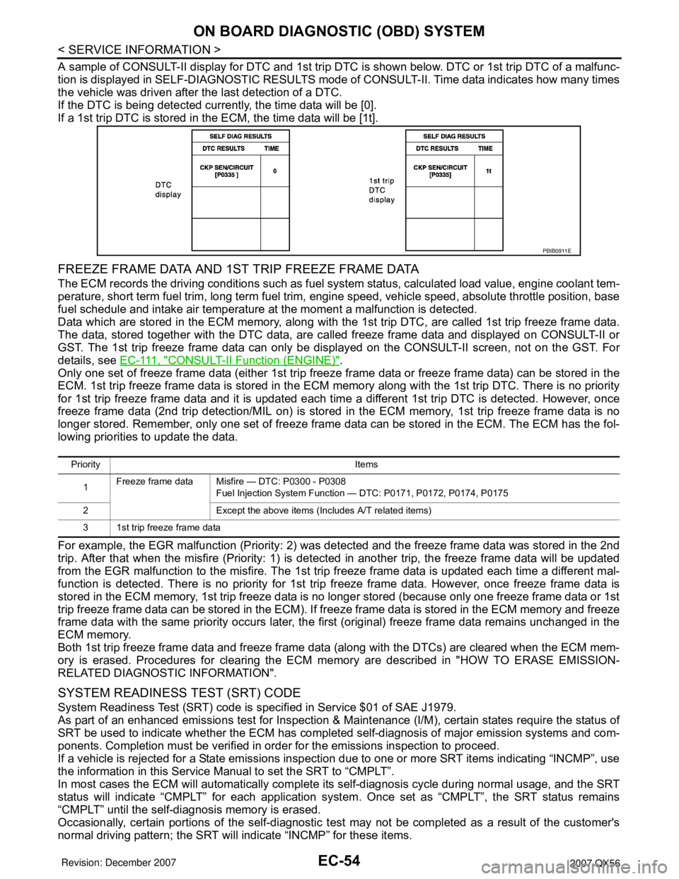
A sample of CONSULT-II display for DTC and 1st trip DTC is shown below. DTC or 1st trip DTC of a malfunc-
tion is displayed in SELF-DIAGNOSTIC RESULTS mode of CONSULT-II. Time data indicates how many times
the vehicle was driven after the last detection of a DTC.
If the DTC is being detected currently, the time data will be [0].
If a 1st trip DTC is stored in the ECM, the time data will be [1t].
FREEZE FRAME DATA AND 1ST TRIP FREEZE FRAME DATA
The ECM records the driving conditions such as fuel system status, calculated load value, engine coolant tem-
perature, short term fuel trim, long term fuel trim, engine speed, vehicle speed, absolute throttle position, base
fuel schedule and intake air temperature at the moment a malfunction is detected.
Data which are stored in the ECM memory, along with the 1st trip DTC, are called 1st trip freeze frame data.
The data, stored together with the DTC data, are called freeze frame data and displayed on CONSULT-II or
GST. The 1st trip freeze frame data can only be displayed on the CONSULT-II screen, not on the GST. For
details, see E C - 111 , "
CONSULT-II Function (ENGINE)".
Only one set of freeze frame data (either 1st trip freeze frame data or freeze frame data) can be stored in the
ECM. 1st trip freeze frame data is stored in the ECM memory along with the 1st trip DTC. There is no priority
for 1st trip freeze frame data and it is updated each time a different 1st trip DTC is detected. However, once
freeze frame data (2nd trip detection/MIL on) is stored in the ECM memory, 1st trip freeze frame data is no
longer stored. Remember, only one set of freeze frame data can be stored in the ECM. The ECM has the fol-
lowing priorities to update the data.
For example, the EGR malfunction (Priority: 2) was detected and the freeze frame data was stored in the 2nd
trip. After that when the misfire (Priority: 1) is detected in another trip, the freeze frame data will be updated
from the EGR malfunction to the misfire. The 1st trip freeze frame data is updated each time a different mal-
function is detected. There is no priority for 1st trip freeze frame data. However, once freeze frame data is
stored in the ECM memory, 1st trip freeze data is no longer stored (because only one freeze frame data or 1st
trip freeze frame data can be stored in the ECM). If freeze frame data is stored in the ECM memory and freeze
frame data with the same priority occurs later, the first (original) freeze frame data remains unchanged in the
ECM memory.
Both 1st trip freeze frame data and freeze frame data (along with the DTCs) are cleared when the ECM mem-
ory is erased. Procedures for clearing the ECM memory are described in "HOW TO ERASE EMISSION-
RELATED DIAGNOSTIC INFORMATION".
SYSTEM READINESS TEST (SRT) CODE
System Readiness Test (SRT) code is specified in Service $01 of SAE J1979.
As part of an enhanced emissions test for Inspection & Maintenance (I/M), certain states require the status of
SRT be used to indicate whether the ECM has completed self-diagnosis of major emission systems and com-
ponents. Completion must be verified in order for the emissions inspection to proceed.
If a vehicle is rejected for a State emissions inspection due to one or more SRT items indicating “INCMP”, use
the information in this Service Manual to set the SRT to “CMPLT”.
In most cases the ECM will automatically complete its self-diagnosis cycle during normal usage, and the SRT
status will indicate “CMPLT” for each application system. Once set as “CMPLT”, the SRT status remains
“CMPLT” until the self-diagnosis memory is erased.
Occasionally, certain portions of the self-diagnostic test may not be completed as a result of the customer's
normal driving pattern; the SRT will indicate “INCMP” for these items.
PBIB0911E
Priority Items
1Freeze frame data Misfire — DTC: P0300 - P0308
Fuel Injection System Function — DTC: P0171, P0172, P0174, P0175
2 Except the above items (Includes A/T related items)
3 1st trip freeze frame data
Page 1154 of 3061

BASIC SERVICE PROCEDURE
EC-71
< SERVICE INFORMATION >
C
D
E
F
G
H
I
J
K
L
MA
EC
N
P O
BASIC SERVICE PROCEDURE
Basic InspectionINFOID:0000000003531609
1.INSPECTION START
1. Check service records for any recent repairs that may indicate a related malfunction, or a current need for
scheduled maintenance.
2. Open engine hood and check the following:
- Harness connectors for improper connections
- Wiring harness for improper connections, pinches and cut
- Vacuum hoses for splits, kinks and improper connections
- Hoses and ducts for leaks
- Air cleaner clogging
- Gasket
3. Confirm that electrical or mechanical loads are not applied.
- Headlamp switch is OFF.
- Air conditioner switch is OFF.
- Rear window defogger switch is OFF.
- Steering wheel is in the straight-ahead position, etc.
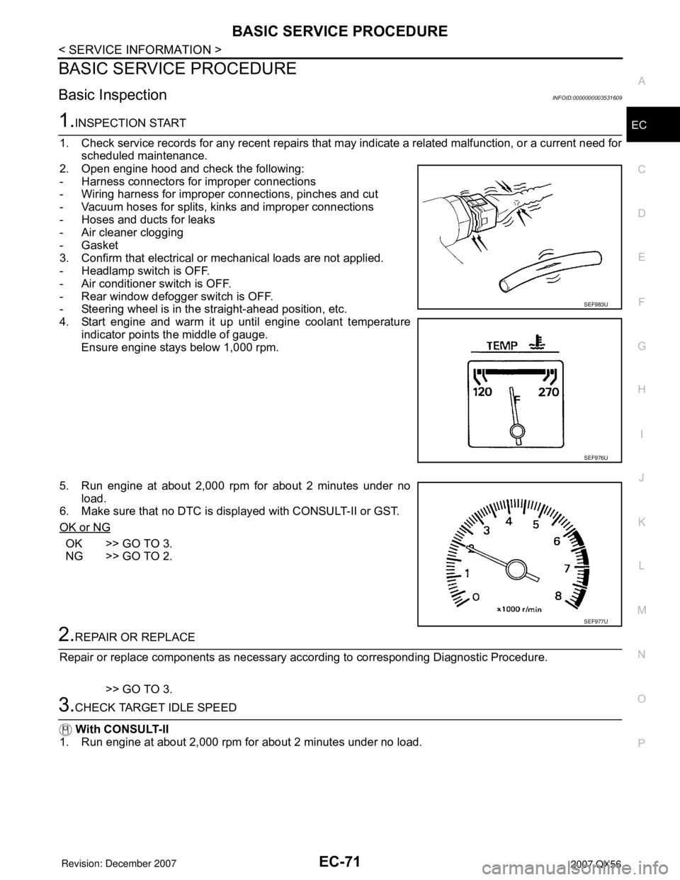
4. Start engine and warm it up until engine coolant temperature
indicator points the middle of gauge.
Ensure engine stays below 1,000 rpm.
5. Run engine at about 2,000 rpm for about 2 minutes under no
load.
6. Make sure that no DTC is displayed with CONSULT-II or GST.
OK or NG
OK >> GO TO 3.
NG >> GO TO 2.
2.REPAIR OR REPLACE
Repair or replace components as necessary according to corresponding Diagnostic Procedure.
>> GO TO 3.
3.CHECK TARGET IDLE SPEED
With CONSULT-II
1. Run engine at about 2,000 rpm for about 2 minutes under no load.
SEF983U
SEF976U
SEF977U
Page 1194 of 3061

TROUBLE DIAGNOSIS
EC-111
< SERVICE INFORMATION >
C
D
E
F
G
H
I
J
K
L
MA
EC
N
P O
: Average voltage for pulse signal (Actual pulse signal can be confirmed by oscilloscope.)
*:Before measuring the terminal voltage, confirm that the battery is fully charged. Refer to SC-4
.
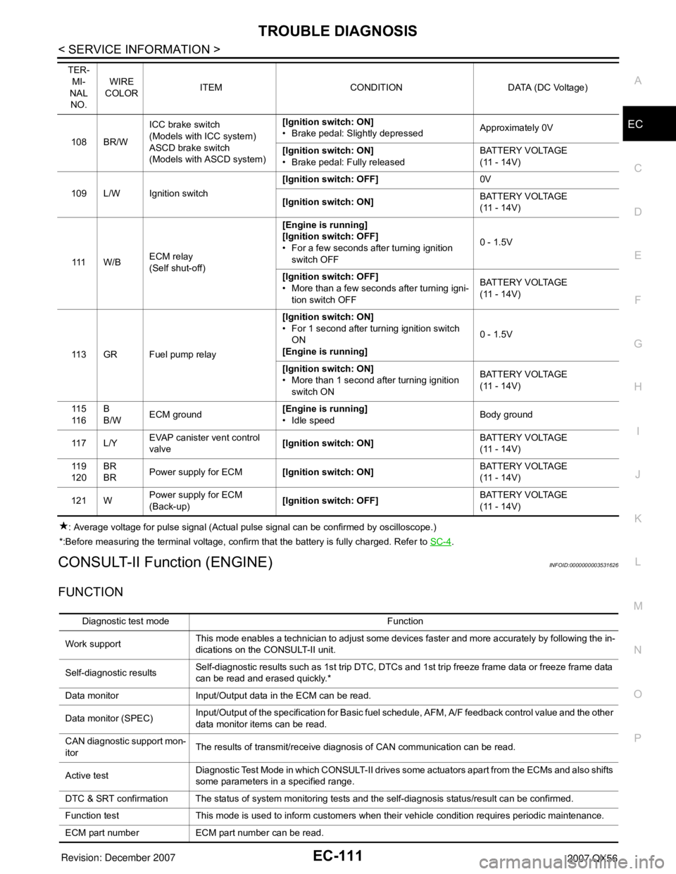
CONSULT-II Function (ENGINE)INFOID:0000000003531626
FUNCTION
108 BR/WICC brake switch
(Models with ICC system)
ASCD brake switch
(Models with ASCD system)[Ignition switch: ON]
• Brake pedal: Slightly depressedApproximately 0V
[Ignition switch: ON]
• Brake pedal: Fully releasedBATTERY VOLTAGE
(11 - 14V)
109 L/W Ignition switch[Ignition switch: OFF]0V
[Ignition switch: ON]BATTERY VOLTAGE
(11 - 14V)
111 W / BECM relay
(Self shut-off)[Engine is running]
[Ignition switch: OFF]
• For a few seconds after turning ignition
switch OFF0 - 1.5V
[Ignition switch: OFF]
• More than a few seconds after turning igni-
tion switch OFFBATTERY VOLTAGE
(11 - 14V)
11 3 G R F u e l p u m p r e l a y[Ignition switch: ON]
• For 1 second after turning ignition switch
ON
[Engine is running]0 - 1.5V
[Ignition switch: ON]
• More than 1 second after turning ignition
switch ONBATTERY VOLTAGE
(11 - 14V)
11 5
11 6B
B/WECM ground[Engine is running]
• Idle speedBody ground
11 7 L / YEVAP canister vent control
valve[Ignition switch: ON]BATTERY VOLTAGE
(11 - 14V)
11 9
120BR
BRPower supply for ECM[Ignition switch: ON]BATTERY VOLTAGE
(11 - 14V)
121 WPower supply for ECM
(Back-up)[Ignition switch: OFF]BATTERY VOLTAGE
(11 - 14V) TER-
MI-
NAL
NO.WIRE
COLORITEM CONDITION DATA (DC Voltage)
Diagnostic test mode Function
Work supportThis mode enables a technician to adjust some devices faster and more accurately by following the in-
dications on the CONSULT-II unit.
Self-diagnostic resultsSelf-diagnostic results such as 1st trip DTC, DTCs and 1st trip freeze frame data or freeze frame data
can be read and erased quickly.*
Data monitor Input/Output data in the ECM can be read.
Data monitor (SPEC)Input/Output of the specification for Basic fuel schedule, AFM, A/F feedback control value and the other
data monitor items can be read.
CAN diagnostic support mon-
itorThe results of transmit/receive diagnosis of CAN communication can be read.
Active testDiagnostic Test Mode in which CONSULT-II drives some actuators apart from the ECMs and also shifts
some parameters in a specified range.
DTC & SRT confirmation The status of system monitoring tests and the self-diagnosis status/result can be confirmed.
Function test This mode is used to inform customers when their vehicle condition requires periodic maintenance.
ECM part number ECM part number can be read.
Page 1197 of 3061

EC-114
< SERVICE INFORMATION >
TROUBLE DIAGNOSIS
*: This function is not necessary in the usual service procedure.
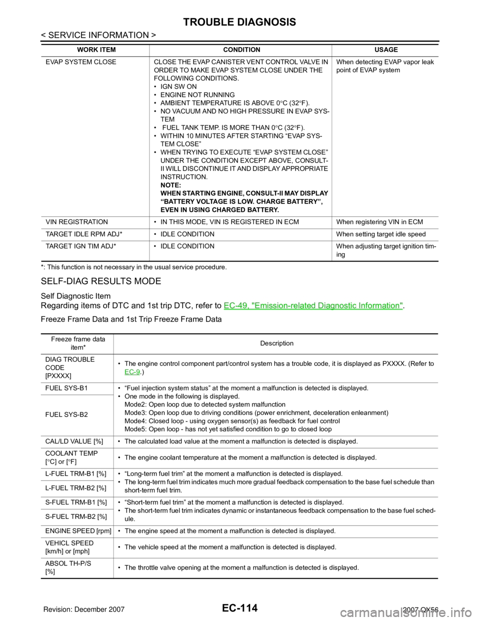
SELF-DIAG RESULTS MODE
Self Diagnostic Item
Regarding items of DTC and 1st trip DTC, refer to EC-49, "Emission-related Diagnostic Information".
Freeze Frame Data and 1st Trip Freeze Frame Data
EVAP SYSTEM CLOSE CLOSE THE EVAP CANISTER VENT CONTROL VALVE IN
ORDER TO MAKE EVAP SYSTEM CLOSE UNDER THE
FOLLOWING CONDITIONS.
• IGN SW ON
• ENGINE NOT RUNNING
• AMBIENT TEMPERATURE IS ABOVE 0°C (32°F).
• NO VACUUM AND NO HIGH PRESSURE IN EVAP SYS-
TEM
• FUEL TANK TEMP. IS MORE THAN 0°C (32°F).
• WITHIN 10 MINUTES AFTER STARTING “EVAP SYS-
TEM CLOSE”
• WHEN TRYING TO EXECUTE “EVAP SYSTEM CLOSE”
UNDER THE CONDITION EXCEPT ABOVE, CONSULT-
II WILL DISCONTINUE IT AND DISPLAY APPROPRIATE
INSTRUCTION.
NOTE:
WHEN STARTING ENGINE, CONSULT-II MAY DISPLAY
“BATTERY VOLTAGE IS LOW. CHARGE BATTERY”,
EVEN IN USING CHARGED BATTERY.When detecting EVAP vapor leak
point of EVAP system
VIN REGISTRATION • IN THIS MODE, VIN IS REGISTERED IN ECM When registering VIN in ECM
TARGET IDLE RPM ADJ* • IDLE CONDITION When setting target idle speed
TARGET IGN TIM ADJ* • IDLE CONDITION When adjusting target ignition tim-
ing WORK ITEM CONDITION USAGE
Freeze frame data
item*Description
DIAG TROUBLE
CODE
[PXXXX]• The engine control component part/control system has a trouble code, it is displayed as PXXXX. (Refer to
EC-9
.)
FUEL SYS-B1 • “Fuel injection system status” at the moment a malfunction is detected is displayed.
• One mode in the following is displayed.
Mode2: Open loop due to detected system malfunction
Mode3: Open loop due to driving conditions (power enrichment, deceleration enleanment)
Mode4: Closed loop - using oxygen sensor(s) as feedback for fuel control
Mode5: Open loop - has not yet satisfied condition to go to closed loop FUEL SYS-B2
CAL/LD VALUE [%] • The calculated load value at the moment a malfunction is detected is displayed.
COOLANT TEMP
[°C] or [°F]• The engine coolant temperature at the moment a malfunction is detected is displayed.
L-FUEL TRM-B1 [%] • “Long-term fuel trim” at the moment a malfunction is detected is displayed.
• The long-term fuel trim indicates much more gradual feedback compensation to the base fuel schedule than
short-term fuel trim. L-FUEL TRM-B2 [%]
S-FUEL TRM-B1 [%] • “Short-term fuel trim” at the moment a malfunction is detected is displayed.
• The short-term fuel trim indicates dynamic or instantaneous feedback compensation to the base fuel sched-
ule. S-FUEL TRM-B2 [%]
ENGINE SPEED [rpm] • The engine speed at the moment a malfunction is detected is displayed.
VEHICL SPEED
[km/h] or [mph]• The vehicle speed at the moment a malfunction is detected is displayed.
ABSOL TH-P/S
[%]• The throttle valve opening at the moment a malfunction is detected is displayed.
Page 1198 of 3061

TROUBLE DIAGNOSIS
EC-115
< SERVICE INFORMATION >
C
D
E
F
G
H
I
J
K
L
MA
EC
N
P O
*: The item is the same as that of 1st trip freeze frame data.
DATA MONITOR MODE
Monitored Item
×: Applicable
B/FUEL SCHDL
[msec]• The base fuel schedule at the moment a malfunction is detected is displayed.
INT/A TEMP SE
[°C] or [°F]• The intake air temperature at the moment a malfunction is detected is displayed. Freeze frame data
item*Description
Monitored item
[Unit]ECM IN-
PUT SIG-
NALSMAIN
SIGNALSDescription Remarks
ENG SPEED [rpm]×ו Indicates the engine speed computed
from the signal of the crankshaft position
sensor (POS) and camshaft position
sensor (PHASE).• Accuracy becomes poor if engine
speed drops below the idle rpm.
• If the signal is interrupted while the en-
gine is running, an abnormal value may
be indicated.
MAS A/F SE-B1 [V]×ו The signal voltage of the mass air flow
sensor is displayed.• When the engine is stopped, a certain
value is indicated.
B/FUEL SCHDL
[msec]ו Base fuel schedule indicates the fuel in-
jection pulse width programmed into
ECM, prior to any learned on board cor-
rection.
A/F ALPHA-B1 [%]×
• The mean value of the air-fuel ratio feed-
back correction factor per cycle is indi-
cated.• When the engine is stopped, a certain
value is indicated.
• This data also includes the data for the
air-fuel ratio learning control. A/F ALPHA-B2 [%]×
COOLAN TEMP/S
[°C] or [°F]×ו The engine coolant temperature (deter-
mined by the signal voltage of the engine
coolant temperature sensor) is dis-
played.• When the engine coolant temperature
sensor is open or short-circuited, ECM
enters fail-safe mode. The engine cool-
ant temperature determined by the
ECM is displayed.
A/F SEN1 (B1) [V]××
• The A/F signal computed from the input
signal of the A/F sensor 1 is displayed.
A/F SEN1 (B2) [V]×
HO2S2 (B1) [V]×
• The signal voltage of the heated oxygen
sensor 2 is displayed.
HO2S2 (B2) [V]×
HO2S2 MNTR (B1)
[RICH/LEAN]ו Display of heated oxygen sensor 2 sig-
nal:
RICH: means the amount of oxygen after
three way catalyst is relatively small.
LEAN: means the amount of oxygen af-
ter three way catalyst is relatively large.• When the engine is stopped, a certain
value is indicated.
HO2S2 MNTR (B2)
[RICH/LEAN]×
VHCL SPEED SE
[km/h] or [mph]×ו The vehicle speed computed from the
vehicle speed signal sent from combina-
tion meter is displayed.
BATTERY VOLT [V]×ו The power supply voltage of ECM is dis-
played.
ACCEL SEN 1 [V]××
• The accelerator pedal position sensor
signal voltage is displayed.• ACCEL SEN 2 signal is converted by
ECM internally. Thus, it differs from
ECM terminal voltage signal. ACCEL SEN 2 [V]×
THRTL SEN 1 [V]××
• The throttle position sensor signal volt-
age is displayed.• THRTL SEN 2 signal is converted by
ECM internally. Thus, it differs from
ECM terminal voltage signal. THRTL SEN 2 [V]×