2006 TOYOTA RAV4 oil pressure
[x] Cancel search: oil pressurePage 391 of 2000

SERVICE SPECIFICATIONS – U241E AUTOMATIC TRANSAXLESS–65
SS
Solenoid wire retaining bolt x Transaxle housing 5.4 55 48 in.*lbf
Transmission valve body x Transaxle case 11 110 8
ATF temperature sensor clamp x Valve body 6.6 67 58 in.*lbf
Valve body oil strainer x Transmission valve 11 110 8
Automatic transaxle oil pan sub-assembly x Transaxle case 7.8 80 69 in.*lbf
Speed sensor x Transaxle case 11.3 115 8
Transmission revolution sensor x Transaxle case 11.3 115 8
Oil cooler tube union x Transaxle case 27 276 20
Oil cooler tube union x Transaxle case 27 280 20
Speedometer driven hole cover sub-assembly x Transaxle case 7.0 7061
Oil pump body x Stator shaft assembly 9.8 100 7
Under drive planetary gear x Lock nut 280 2,855 207
Line pressure control solenoid assembly x Transmission valve body assembly 11 110 8
No. 1 clutch control solenoid assembly x Transmission valve body assembly 11 110 8
Automatic transmission 3 way solenoid assembly x Transmission valve body assembly 11 110 8
No. 2 clutch control solenoid assembly x Transmission valve body assembly 11 110 8
No. 2 transmission 3 way solenoid assembly x Transmission valve body assembly 11 110 8
Front differential case x Front differential ring gear 95.1 970 70Part Tightened N*m kgf*cm ft.*lbf
Page 560 of 2000

ES–362GR-FE ENGINE CONTROL SYSTEM – SFI SYSTEM
ES
VV2+ (B30-67) - VV2- (B30-90) W - B Variable valve timing
(VVT) sensor (Intake side
(bank 2))Idling Pulse generation
(see waveform 5)
EV1+ (B30-68) - EV1- (B30-91) Y - G Variable valve timing
(VVT) sensor (Exhaust
side (bank 1))Idling Pulse generation
(see waveform 5)
EV2+ (B30-66) - EV2- (B30-89) R - L Variable valve timing
(VVT) sensor (Exhaust
side (bank 2))Idling Pulse generation
(see waveform 5)
NE+ (B30-110) - NE- (B30-111) G - R Crankshaft position sensor Idling Pulse generation (see
waveform 5)
IGT1 (B30-40) - E1 (B30-81)
IGT2 (B30-39) - E1 (B30-81)
IGT3 (B30-38) - E1 (B30-81)
IGT4 (B30-37) - E1 (B30-81)
IGT5 (B30-36) - E1 (B30-81)
IGT6 (B30-35) - E1 (B30-81)W - BR
G-R - BR
G - BR
LG - BR
P - BR
V - BRIgnition coil (ignition
signal)Idling Pulse generation (see
waveform 6)
IGF1 (B30-106) - E1 (B30-81) Y - BR Ignition coil (ignition
confirmation signal)Ignition switch ON 4.5 to 5.5 V
Idling Pulse generation (see
waveform 6)
PRG (B30-108) - E1 (B30-81) LG - BR Purge VSV Ignition switch ON 9 to 14 V
Idling Pulse generation (see
waveform 7)
SPD (A9-8) - E1 (B30-81) V - BR Speed signal from
combination meterDriving at 20 km/h (12 mph) Pulse generation (see
waveform 8)
STA (A9-48) - E1 (B30-81) LG - BR Starter signal Cranking 5.5 V or more
NSW (B30-62) - E1 (B30-81) G-R - BR Starter relay control Ignition switch ON Below 1.5 V
Cranking 6.0 V or more
STP (A9-36) - E1 (B30-81) L - BR Stop light switch Brake pedal depressed 7.5 to 14 V
Brake pedal released Below 1.5 V
ST1- (A9-35) - E1 (B30-81) GR - BR Stop light switch
(opposite to STP terminal)Ignition switch ON,
Brake pedal depressedBelow 1.5 V
Ignition switch ON,
Brake pedal released7.5 to 14 V
M+ (B30-19) - ME01 (B30-20) G - BR Throttle actuator Idling with warm engine Pulse generation (see
waveform 9)
M- (B30-18) - ME01 (B30-20) R - BR Throttle actuator Idling with warm engine Pulse generation (see
waveform 10)
FC (A9-7) - E1 (B30-81) W - BR Fuel pump control Ignition switch ON 9 to 14 V
Idling Below 1.5 V
FPR (B30-59) - E1 (B30-81) W - BR Fuel pump control Cranking 9 to 14 V
FPR (B30-59) - E1 (B30-81) W - BR Fuel pump control Idling 9 to 14 V
W (A9-24) - E1 (B30-81) R - BR MIL Ignition switch ON Below 1.5 V
Idling 9 to 14 V
TC (A9-27) - E1 (B30-81) G - BR Terminal TC of DLC3 Ignition switch ON 9 to 14 V
TACH (A9-15) - E1 (B30-81) GR - BR Engine speed Idling Pulse generation (see
waveform 11)
VPMP (A9-42) - E1 (B30-81) W - BR Vent valve (built into
canister pump module)Ignition switch ON 9 to 14 V
MPMP (A9-34) - E1 (B30-81) B - BR Leak detection pump (built
into canister pump
module)Leak detection pump OFF Below 3 V
Leak detection pump ON 9 to 14 V
VCPP (B30-75) - EPPM (B30-76) V - BR Power source for canister
pressure sensor (specific
voltage)Ignition switch ON 4.5 to 5.5 V Symbol (Terminal No.) Wiring Color Terminal Description Condition Specified Condition
Page 561 of 2000

2GR-FE ENGINE CONTROL SYSTEM – SFI SYSTEMES–37
ES
HINT:
*: The ECM terminal voltage is constant regardless
of the output voltage from the sensor.
(b) WAVEFORM 1
Camshaft timing oil control valve (OCV)
PPMP (B30-77) - EPPM (B30-76) L - BR Canister pressure sensor
(built into canister pump
module)Ignition switch ON 3 to 3.6 V
ELS (A9-31) - E1 (B30-81) O - BR Electric load Taillight switch ON7.5 to 14 V
Taillight switch OFF Below 1.5 V
ELS2 (A9-33) - E1 (B30-81) G - BR Electric load Defogger switch ON7.5 to 14 V
Defogger switch OFF Below 1.5 V
ALT (B30-32) - E1 (B30-81) P - BR Generator Ignition switch ON 9 to 14 V
CANH (A9-41) - E1 (B30-81) Y - BR CAN communication line Ignition switch ON Pulse generation (see
waveform 12)
CANL (A9-49) - E1 (B30-81) W - BR CAN communication line Ignition switch ON Pulse generation (see
waveform 13)
VCIB (B30-80) - EIB (B30-101) LG - P Battery current sensor Ignition switch ON 4.5 to 5.5 V
IB (B30-100) - EIB (B30-101) R - P Battery current sensor Ignition switch ON 0.5 to 2.5 V
THB (B30-103) - EIB (B30-101) G-R - P Battery temperature
sensorIgnition switch ON, battery
temperature -30 to 80
C (-22 to
176
F)0.5 to 4.5 V
RLO (B30-31) - E1 (B30-81) Y - BR Generator After engine warmed up, during
charging control, vehicle driven at
constant speedPulse generation (see
waveform 14)
RLO (B30-31) - E1 (B30-81) Y - BR Generator After engine warmed up, during
charging control, vehicle
acceleratedPulse generation (see
waveform 15)
RLO (B30-31) - E1 (B30-81) Y - BR Generator After engine warmed up, during
charging control, vehicle
deceleratedPulse generation (see
waveform 16)
AICV (A9-4) - E1 (B30-81) L - BR VSV for air intake control
system operation signalIgnition switch ON 9 to 14 V
ACIS (B30-107) - E1 (B30-81) R - BR VSV for ACIS (Acoustic
Control Induction System)
operation signalIgnition switch ON 9 to 14 V Symbol (Terminal No.) Wiring Color Terminal Description Condition Specified Condition
A093229E02
Symbol (Terminal No.) Between OC1+ and OC1-
Between OC2+ and OC2-
Between OE1+ and OE1-
Between OE2+ and OE2-
Tester Range 5 V/DIV., 1 msec./DIV.
Condition Idling
Page 601 of 2000

2AZ-FE ENGINE MECHANICAL – CYLINDER HEADEM–57
EM
REMOVAL
1. DISCHARGE FUEL SYSTEM PRESSURE (See page
FU-9)
2. DISCONNECT CABLE FROM NEGATIVE BATTERY
TERMINAL
CAUTION:
Wait at least 90 seconds after disconnecting the
cable from the negative (-) battery terminal to
prevent airbag and seat belt pretensioner activation.
3. REMOVE RADIATOR SUPPORT OPENING COVER
4. REMOVE FRONT WHEEL RH
5. REMOVE NO. 1 ENGINE UNDER COVER
6. REMOVE FRONT FENDER APRON RH
7. REMOVE NO. 1 ENGINE COVER (See page EM-22)
8. DRAIN ENGINE COOLANT (See page CO-6)
9. DRAIN ENGINE OIL (See page LU-4)
10. REMOVE AIR CLEANER CAP (See page ES-411)
11. REMOVE THROTTLE BODY (See page ES-412)
12. REMOVE FUEL DELIVERY PIPE SUB-ASSEMBLY
(See page FU-10)
13. REMOVE INTAKE MANIFOLD (See page ES-419)
14. REMOVE INTAKE MANIFOLD INSULATOR (See page
ES-420)
15. REMOVE FRONT EXHAUST PIPE (See page EX-3)
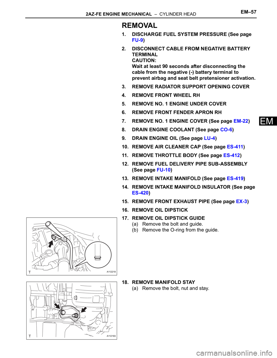
16. REMOVE OIL DIPSTICK
17. REMOVE OIL DIPSTICK GUIDE
(a) Remove the bolt and guide.
(b) Remove the O-ring from the guide.
18. REMOVE MANIFOLD STAY
(a) Remove the bolt, nut and stay.
A112218
A112193
Page 603 of 2000

2AZ-FE ENGINE MECHANICAL – CYLINDER HEADEM–59
EM
23. DISCONNECT ENGINE WIRE
(a) Disconnect the radio setting condenser connector.
(b) Disconnect the engine oil pressure switch
connector.
(c) Disconnect the engine coolant temperature sensor
connector.
(d) Disconnect the camshaft position sensor connector.
(e) Remove the bolt and ground cable.
24. REMOVE FRONT SUSPENSION MEMBER
REINFORCEMENT RH (See page EM-6)
25. REMOVE FAN AND GENERATOR V BELT (See page
EM-6)
26. REMOVE GENERATOR ASSEMBLY (See page CH-9)
27. REMOVE ENGINE MOUNTING INSULATOR RH (See
page EM-22)
28. REMOVE IDLER PULLEY (See page EM-23)
29. REMOVE IGNITION COIL ASSEMBLY (See page IG-9)
30. REMOVE SPARK PLUG (See page EM-8)
31. REMOVE CYLINDER HEAD COVER SUB-ASSEMBLY
(See page EM-24)
32. REMOVE V-RIBBED BELT TENSIONER ASSEMBLY
(See page EM-26)
33. REMOVE CRANKSHAFT POSITION SENSOR (See
page ES-402)
34. REMOVE OIL PAN SUB-ASSEMBLY (See page EM-
24)
35. SET NO. 1 CYLINDER TO TDC/COMPRESSION
(a) Turn the crankshaft pulley until its groove and the
timing mark "0" of the timing chain cover are
aligned.
(b) Check that each timing mark of the camshaft timing
gear and sprocket is aligned with each timing mark
located on the No. 1 and No. 2 bearing caps as
shown in the illustration.
If not, turn the crankshaft by 1 revolution (360
) to
align the timing marks as above.
A098748E01
A098345E09
Page 606 of 2000

EM–622AZ-FE ENGINE MECHANICAL – CYLINDER HEAD
EM
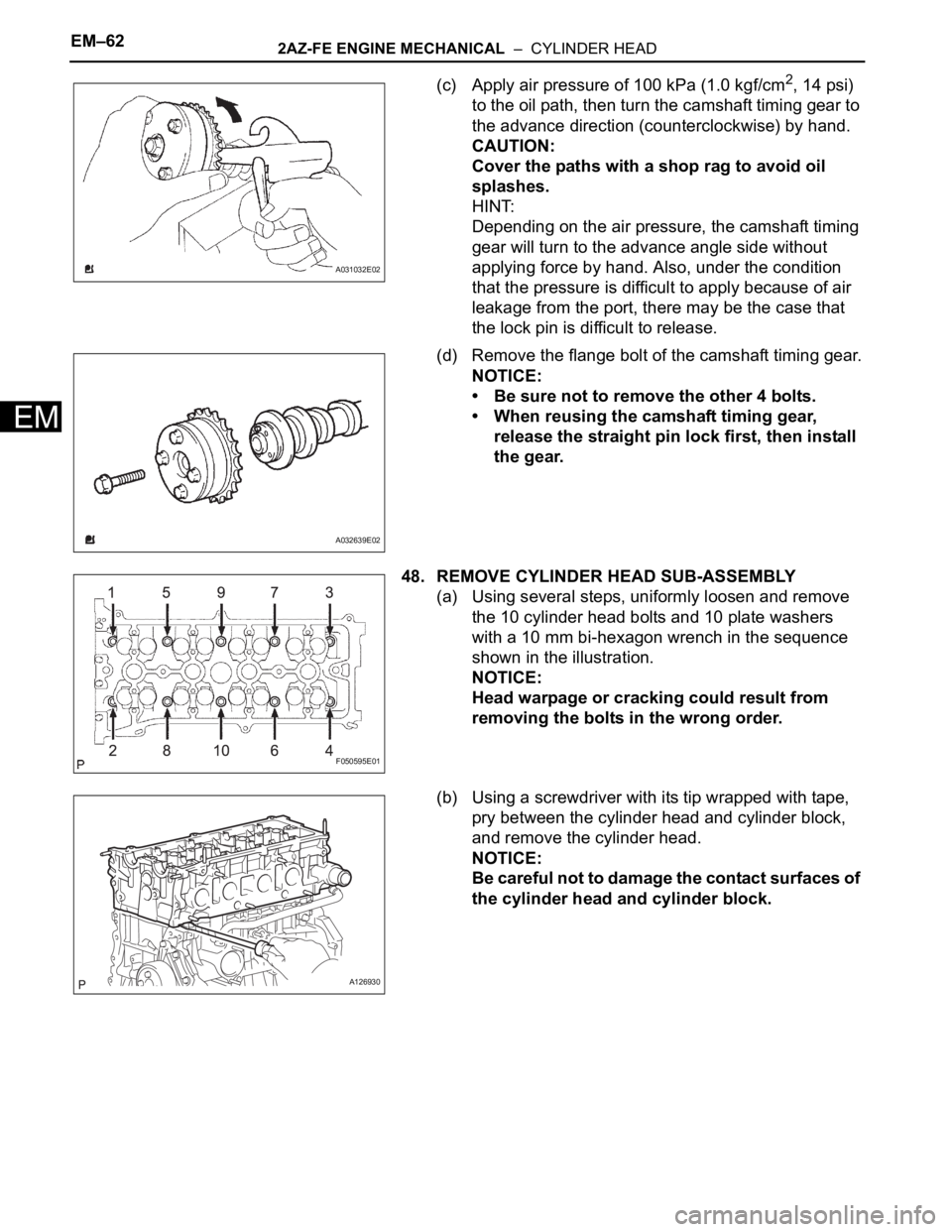
(c) Apply air pressure of 100 kPa (1.0 kgf/cm2, 14 psi)
to the oil path, then turn the camshaft timing gear to
the advance direction (counterclockwise) by hand.
CAUTION:
Cover the paths with a shop rag to avoid oil
splashes.
HINT:
Depending on the air pressure, the camshaft timing
gear will turn to the advance angle side without
applying force by hand. Also, under the condition
that the pressure is difficult to apply because of air
leakage from the port, there may be the case that
the lock pin is difficult to release.
(d) Remove the flange bolt of the camshaft timing gear.
NOTICE:
• Be sure not to remove the other 4 bolts.
• When reusing the camshaft timing gear,
release the straight pin lock first, then install
the gear.
48. REMOVE CYLINDER HEAD SUB-ASSEMBLY
(a) Using several steps, uniformly loosen and remove
the 10 cylinder head bolts and 10 plate washers
with a 10 mm bi-hexagon wrench in the sequence
shown in the illustration.
NOTICE:
Head warpage or cracking could result from
removing the bolts in the wrong order.
(b) Using a screwdriver with its tip wrapped with tape,
pry between the cylinder head and cylinder block,
and remove the cylinder head.
NOTICE:
Be careful not to damage the contact surfaces of
the cylinder head and cylinder block.
A031032E02
A032639E02
F050595E01
A126930
Page 607 of 2000

2AZ-FE ENGINE MECHANICAL – CYLINDER HEADEM–63
EM
49. REMOVE CYLINDER HEAD GASKET
DISASSEMBLY
1. REMOVE RADIO SETTING CONDENSER
(a) Remove the bolt and condenser.
2. REMOVE OIL PRESSURE SWITCH
(a) Using a 24 mm deep socket wrench, remove the
sensor.
3. REMOVE ENGINE COOLANT TEMPERATURE
SENSOR
(a) Using SST, remove the sensor and gasket.
SST 09817-33190
A126929
A112227
A114362
A114367E01
Page 611 of 2000

2AZ-FE ENGINE MECHANICAL – CYLINDER HEADEM–67
EM
4. INSPECT CAMSHAFT TIMING GEAR ASSEMBLY
(a) Check the lock of the camshaft timing gear.
(1) Clamp the camshaft in a vise, and confirm that
the camshaft timing gear is locked.
NOTICE:
Be careful not to damage the camshaft.
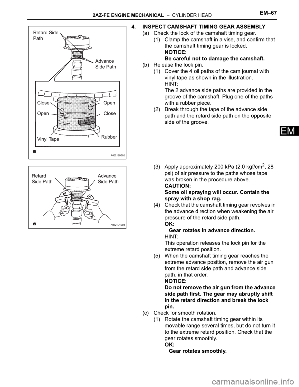
(b) Release the lock pin.
(1) Cover the 4 oil paths of the cam journal with
vinyl tape as shown in the illustration.
HINT:
The 2 advance side paths are provided in the
groove of the camshaft. Plug one of the paths
with a rubber piece.
(2) Break through the tape of the advance side
path and the retard side path on the opposite
side of the groove.
(3) Apply approximately 200 kPa (2.0 kgf/cm
2, 28
psi) of air pressure to the paths whose tape
was broken in the procedure above.
CAUTION:
Some oil spraying will occur. Contain the
spray with a shop rag.
(4) Check that the camshaft timing gear revolves in
the advance direction when weakening the air
pressure of the retard side path.
OK:
Gear rotates in advance direction.
HINT:
This operation releases the lock pin for the
extreme retard position.
(5) When the camshaft timing gear reaches the
extreme advance position, remove the air gun
from the retard side path and advance side
path, in that order.
NOTICE:
Do not remove the air gun from the advance
side path first. The gear may abruptly shift
in the retard direction and break the lock
pin.
(c) Check for smooth rotation.
(1) Rotate the camshaft timing gear within its
movable range several times, but do not turn it
to the extreme retard position. Check that the
gear rotates smoothly.
OK:
Gear rotates smoothly.
A062190E02
A062191E03