Page 1140 of 2000

U151F AUTOMATIC TRANSAXLE – AUTOMATIC TRANSAXLE SYSTEMAX–21
AX
(12)Turn the ignition switch off.
(13)Remove SST, and install the test plug A.
(14)Remove the test plug B, install SST and start
the engine.
SST 09992-00095 (09992-00231, 09992-
00271)
(15)Connect the transmission wire connector,
depress the brake pedal firmly, shift to the R
position and check the line pressure while the
engine is idling and during the stall test.
Specified line pressure:
(16)Remove SST, and install the test plug B.
(17)Clear the DTC.
Evaluation:
Condition
R position kPa (kgf/cm2, psi)
Idling 672 to 742 kPa
(6.9 to 7.6 kgf/cm
2, 97 to 108 psi)
Stall test 1,768 to 1,968 kPa
(18.0 to 20.0 kgf/cm
2, 256 to 285 psi)
Problem Possible cause
Measured values at all positions are higher than specified • Shift solenoid valve SLT defective
• Regulator valve defective
Measured values at all positions are lower than specified • Shift solenoid valve SLT defective
• Regulator valve defective
• Oil pump defective
• U/D (underdrive) direct clutch defective
Pressure is low when shift lever is on D only • D position circuit fluid leak
• Forward clutch defective
Pressure is low when shift lever is on R only • R position circuit fluid leak
• Reverse clutch defective
• 1st and reverse brake defective
Page 1194 of 2000
AX–216U151F AUTOMATIC TRANSAXLE – AUTOMATIC TRANSAXLE UNIT
AX
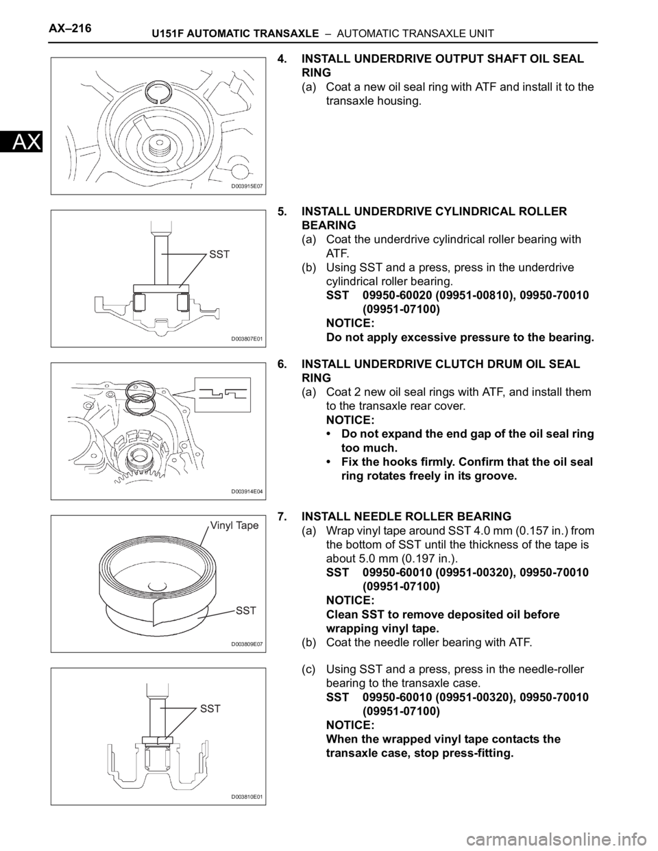
4. INSTALL UNDERDRIVE OUTPUT SHAFT OIL SEAL
RING
(a) Coat a new oil seal ring with ATF and install it to the
transaxle housing.
5. INSTALL UNDERDRIVE CYLINDRICAL ROLLER
BEARING
(a) Coat the underdrive cylindrical roller bearing with
AT F.
(b) Using SST and a press, press in the underdrive
cylindrical roller bearing.
SST 09950-60020 (09951-00810), 09950-70010
(09951-07100)
NOTICE:
Do not apply excessive pressure to the bearing.
6. INSTALL UNDERDRIVE CLUTCH DRUM OIL SEAL
RING
(a) Coat 2 new oil seal rings with ATF, and install them
to the transaxle rear cover.
NOTICE:
• Do not expand the end gap of the oil seal ring
too much.
• Fix the hooks firmly. Confirm that the oil seal
ring rotates freely in its groove.
7. INSTALL NEEDLE ROLLER BEARING
(a) Wrap vinyl tape around SST 4.0 mm (0.157 in.) from
the bottom of SST until the thickness of the tape is
about 5.0 mm (0.197 in.).
SST 09950-60010 (09951-00320), 09950-70010
(09951-07100)
NOTICE:
Clean SST to remove deposited oil before
wrapping vinyl tape.
(b) Coat the needle roller bearing with ATF.
(c) Using SST and a press, press in the needle-roller
bearing to the transaxle case.
SST 09950-60010 (09951-00320), 09950-70010
(09951-07100)
NOTICE:
When the wrapped vinyl tape contacts the
transaxle case, stop press-fitting.
D003915E07
D003807E01
D003914E04
D003809E07
D003810E01
Page 1244 of 2000

AX–20U241E AUTOMATIC TRANSAXLE – AUTOMATIC TRANSAXLE SYSTEM
AX
(g) Depress the accelerator pedal as much as possible
with your right foot. Quickly read the highest line
pressure reading when the engine speed reaches
stall speed.
(h) Perform the measure line pressure test again with
the shift lever on R.
Specified line pressure:
Evaluation:
Condition Shift Lever on D Shift Lever on R
Idling 372 to 412 kPa
(3.8 to 4.2 kgf/cm
2, 54 to 60 psi)672 to 742 kPa
(6.9 to 7.6 kgf/cm2, 97 to 108 psi)
Stall 931 to 1,031 kPa
(9.5 to 10.5 kgf/cm
2, 135 to 150 psi)1,768 to 1,968 kPa
(18.0 to 20.0 kgf/cm2, 256 to 285 psi)
Problem Possible Cause
Measured values at all positions are higher than specified • Shift solenoid valve SLT defective
• Regulator valve defective
Measured values at all positions are lower than specified • Shift solenoid valve SLT defective
• Regulator valve defective
• Oil pump defective
• U/D (underdrive) direct clutch defective
Pressure is low when shift lever is on D only • D position circuit fluid leak
• Forward clutch defective
Pressure is low when shift lever is on R only • R position circuit fluid leak
• Direct clutch defective
• 1st and reverse brake defective
Page 1311 of 2000
U241E AUTOMATIC TRANSAXLE – AUTOMATIC TRANSAXLE UNITAX–207
AX
HINT:
End play = Dimension E - Dimension D - thrust
bearing thickness 3.28 mm (0.1291 in.) - underdrive
thrust bearing race thickness.
Standard race thickness
Standard bearing and bearing race diameter
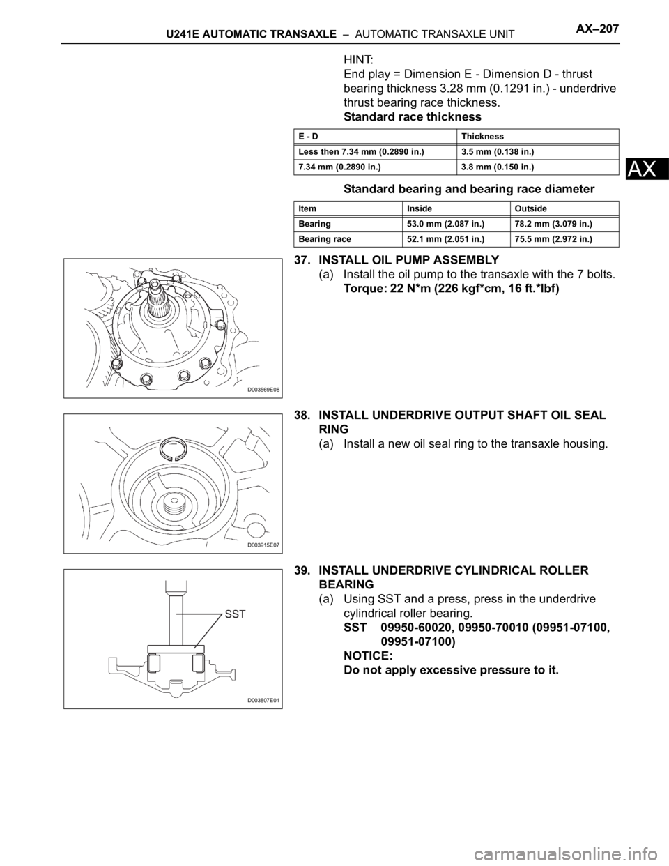
37. INSTALL OIL PUMP ASSEMBLY
(a) Install the oil pump to the transaxle with the 7 bolts.
Torque: 22 N*m (226 kgf*cm, 16 ft.*lbf)
38. INSTALL UNDERDRIVE OUTPUT SHAFT OIL SEAL
RING
(a) Install a new oil seal ring to the transaxle housing.
39. INSTALL UNDERDRIVE CYLINDRICAL ROLLER
BEARING
(a) Using SST and a press, press in the underdrive
cylindrical roller bearing.
SST 09950-60020, 09950-70010 (09951-07100,
09951-07100)
NOTICE:
Do not apply excessive pressure to it.
E - D Thickness
Less then 7.34 mm (0.2890 in.) 3.5 mm (0.138 in.)
7.34 mm (0.2890 in.) 3.8 mm (0.150 in.)
Item Inside Outside
Bearing 53.0 mm (2.087 in.) 78.2 mm (3.079 in.)
Bearing race 52.1 mm (2.051 in.) 75.5 mm (2.972 in.)
D003569E08
D003915E07
D003807E01
Page 1950 of 2000
ES–622AZ-FE ENGINE CONTROL SYSTEM – SFI SYSTEM
ES
P0300 Random / Multiple
Cylinder Misfire
Detected- Open or short in
engine wire harness
- Connector
connection
- Vacuum hose
connection
- Ignition system
- Injector
- Fuel pressure
- MAF meter
- ECT sensor
- Compression
pressure
- Valve clearance
- Valve timing
- PCV valve and hose
- PCV hose
connections
- Air induction system
- ECMComes on/Blinks* DTC storedES-156
P0301 Cylinder 1 Misfire
Detected- Same as DTC
P0300Comes on/Blinks* DTC storedES-156
P0302 Cylinder 2 Misfire
Detected- Same as DTC
P0300Comes on/Blinks* DTC storedES-156
P0303 Cylinder 3 Misfire
Detected- Same as DTC
P0300Comes on/Blinks* DTC storedES-156
P0304 Cylinder 4 Misfire
Detected- Same as DTC
P0300Comes on/Blinks* DTC storedES-156
P0327 Knock Sensor 1
Circuit Low Input
(Bank 1 or Single
Sensor)- Short in knock
sensor circuit
- Knock sensor
- ECMComes on DTC storedES-168
P0328 Knock Sensor 1
Circuit High Input
(Bank 1 or Single
Sensor)- Open in knock
sensor circuit
- Knock sensor
- ECMComes on DTC storedES-168
P0335 Crankshaft Position
Sensor "A" Circuit- Open or short in
Crankshaft Position
(CKP) sensor circuit
- CKP sensor
- CKP sensor plate
- ECMComes on DTC storedES-172
P0339 Crankshaft Position
Sensor "A" Circuit
Intermittent- Same as DTC
P0335- DTC storedES-172
P0340 Camshaft Position
Sensor "A" Circuit
(Bank 1 or Single
Sensor)- Open or short in
Camshaft Position
(CMP) sensor circuit
- CMP sensor
- Camshaft
- Jumped tooth of
timing chain
- ECMComes on DTC storedES-178
P0351 Ignition Coil "A"
Primary / Secondary
Circuit- Ignition system
- Open or short in
IGF1 or IGT circuit (1
to 4) between ignition
coil with igniter and
ECM
- No. 1 to No. 4
ignition coils with
igniters
- ECMComes on DTC storedES-183 DTC No. Detection Item Trouble Areas MIL Memory See page
Page 1951 of 2000
2AZ-FE ENGINE CONTROL SYSTEM – SFI SYSTEMES–63
ES
P0352 Ignition Coil "B"
Primary / Secondary
Circuit- Same as DTC
P0351Comes on DTC storedES-183
P0353 Ignition Coil "C"
Primary / Secondary
Circuit- Same as DTC
P0351Comes on DTC storedES-183
P0354 Ignition Coil "D"
Primary / Secondary
Circuit- Same as DTC
P0351Comes on DTC storedES-183
P0420 Catalyst System
Efficiency Below
Threshold (Bank 1)- Front exhaust pipe
(with Three-Way
Catalytic Converter)
- Gas leakage from
exhaust system
- A/F sensor (sensor
1)
- HO2 sensor (sensor
2)Comes on DTC storedES-191
P043E Evaporative Emission
System Reference
Orifice Clog Up- Canister pump
module (Reference
orifice, leak detection
pump, vent valve)
- Connector/wire
harness (Canister
pump module - ECM)
- EVAP system hose
(pipe from air inlet
port to canister pump
module, canister
filter, fuel tank vent
hose)
- ECMComes on DTC storedES-198
P043F Evaporative Emission
System Reference
Orifice High Flow- Same as DTC
P043EComes on DTC storedES-198
P0441 Evaporative Emission
Control System
Incorrect Purge Flow- Purge VSV
- Connector/wire
harness (Purge VSV
- ECM)
- Canister pump
module
- Leakage from EVAP
system
- Leakage from EVAP
line (Purge VSV -
Intake manifold)
- ECMComes on DTC storedES-203
P0450 Evaporative Emission
Control System
Pressure Sensor /
Switch- Canister pump
module
- EVAP system hose
(pipe from air inlet
port to canister pump
module, canister
filter, fuel tank vent
hose)
- ECMComes on DTC storedES-210 DTC No. Detection Item Trouble Areas MIL Memory See page
Page 1957 of 2000
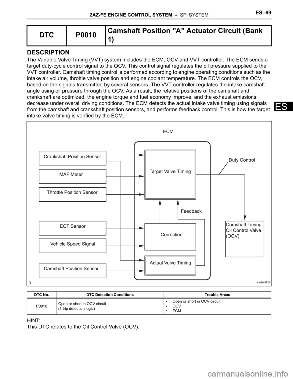
2AZ-FE ENGINE CONTROL SYSTEM – SFI SYSTEMES–69
ES
DESCRIPTION
The Variable Valve Timing (VVT) system includes the ECM, OCV and VVT controller. The ECM sends a
target duty-cycle control signal to the OCV. This control signal regulates the oil pressure supplied to the
VVT controller. Camshaft timing control is performed according to engine operating conditions such as the
intake air volume, throttle valve position and engine coolant temperature. The ECM controls the OCV,
based on the signals transmitted by several sensors. The VVT controller regulates the intake camshaft
angle using oil pressure through the OCV. As a result, the relative positions of the camshaft and
crankshaft are optimized, the engine torque and fuel economy improve, and the exhaust emissions
decrease under overall driving conditions. The ECM detects the actual intake valve timing using signals
from the camshaft and crankshaft position sensors, and performs feedback control. This is how the target
intake valve timing is verified by the ECM.
HINT:
This DTC relates to the Oil Control Valve (OCV).
DTC P0010Camshaft Position "A" Actuator Circuit (Bank
1)
DTC No. DTC Detection Conditions Trouble Areas
P0010Open or short in OCV circuit
(1 trip detection logic)• Open or short in OCV circuit
•OCV
•ECM
A103843E08
Page 1958 of 2000

E S –702AZ-FE ENGINE CONTROL SYSTEM – SFI SYSTEM
ES
MONITOR DESCRIPTION
The ECM optimizes the valve timing using the VVT system to control the intake camshaft. The VVT
system includes the ECM, the OCV and the VVT controller. The ECM sends a target duty-cycle control
signal to the OCV. This control signal regulates the oil pressure supplied to the VVT controller. The VVT
controller can advance or retard the intake camshaft.
After the ECM sends the target duty-cycle control signal to the OCV, the ECM monitors the OCV current
to establish an actual duty-cycle. The ECM determines the existence of a malfunction and sets the DTC
when the actual duty-cycle ratio varies from the target duty-cycle ratio.
MONITOR STRATEGY
TYPICAL ENABLING CONDITIONS
TYPICAL MALFUNCTION THRESHOLDS
COMPONENT OPERATING RANGE
Related DTCs P0010: VVT OCV range check
Required Sensors/Components (Main) VVT OCV
Required Sensors/Components (Related) -
Frequency of Operation Continuous
Duration 1 second
MIL Operation Immediate
Sequence of Operation None
Monitor runs whenever following DTCs not present None
All of following conditions met -
Starter OFF
Ignition switch ON
Time after ignition switch OFF to ON 0.5 seconds or more
One of following conditions met -
A. All of following conditions met -
Battery voltage 11 to 13 V
Target duty ratio Less than 70 %
Output signal duty ratio 100 %
B. All of following conditions met -
Battery voltage 13 V or more
Target duty ratio Less than 80 %
Output signal duty ratio 100 %
C. Both of following conditions met -
Current cut status Not cut
Output signal duty ratio 3 % or less
VVT OCV duty ratio 3 to 100 %