Page 809 of 2000
FU–202GR-FE FUEL – FUEL PRESSURE PULSATION DAMPER
FU
INSTALLATION
1. INSTALL FUEL PRESSURE PULSATION DAMPER
(a) Apply a light coat of spindle oil or gasoline to a new
O-ring, and install it to the pulsation damper.
(b) Install the pulsation damper to the fuel delivery pipe.
(c) Install the clip.
2. INSTALL INTAKE AIR SURGE TANK ASSEMBLY (See
page EM-34)
3. INSTALL ENGINE ASSEMBLY
(a) Install the engine (see page EM-31).
4. CONNECT CABLE TO NEGATIVE BATTERY
TERMINAL
Page 832 of 2000

EC–82GR-FE EMISSION CONTROL – EMISSION CONTROL SYSTEM
EC
ON-VEHICLE INSPECTION
1. CHECK FUEL CUT RPM
(a) Increase the engine speed to at least 3,500 rpm.
(b) Use a sound scope to check for injector operating
noise.
(c) Check that the operating sounds stop momentarily
and then resume when the throttle lever is released.
HINT:
Measure with the A/C OFF.
Fuel return rpm:
1,400 rpm
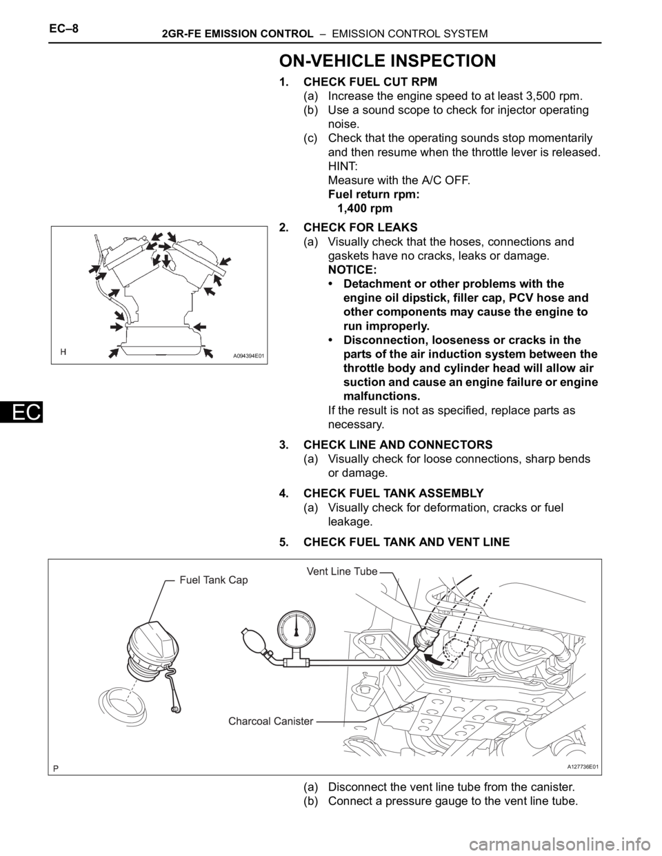
2. CHECK FOR LEAKS
(a) Visually check that the hoses, connections and
gaskets have no cracks, leaks or damage.
NOTICE:
• Detachment or other problems with the
engine oil dipstick, filler cap, PCV hose and
other components may cause the engine to
run improperly.
• Disconnection, looseness or cracks in the
parts of the air induction system between the
throttle body and cylinder head will allow air
suction and cause an engine failure or engine
malfunctions.
If the result is not as specified, replace parts as
necessary.
3. CHECK LINE AND CONNECTORS
(a) Visually check for loose connections, sharp bends
or damage.
4. CHECK FUEL TANK ASSEMBLY
(a) Visually check for deformation, cracks or fuel
leakage.
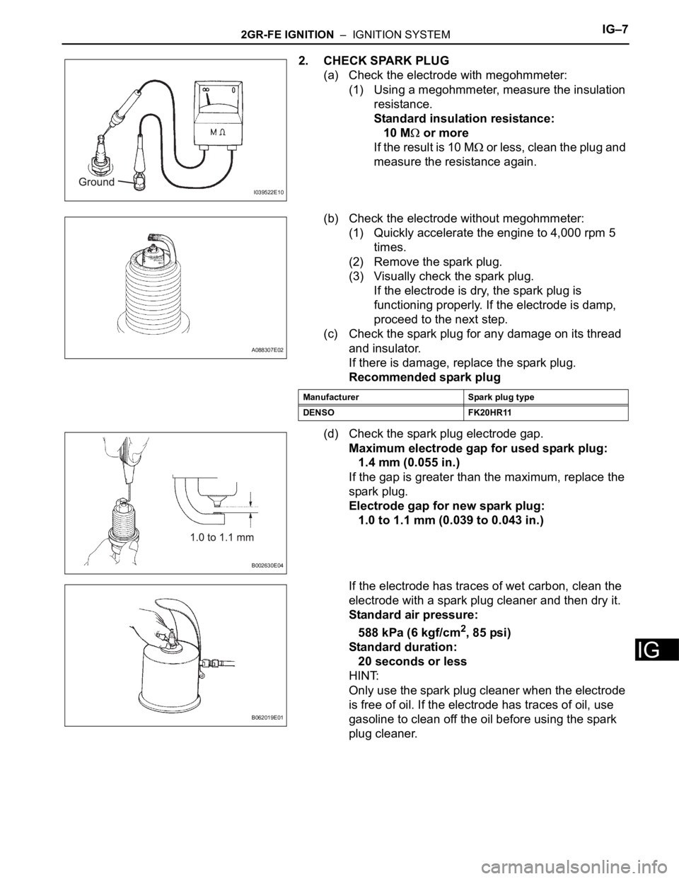
5. CHECK FUEL TANK AND VENT LINE
(a) Disconnect the vent line tube from the canister.
(b) Connect a pressure gauge to the vent line tube.
A094394E01
A127736E01
Page 888 of 2000
IG–82AZ-FE IGNITION – IGNITION SYSTEM
IG
(e) Clean the spark plugs.
If the electrode has traces of wet carbon, clean the
electrode with a spark plug cleaner and then dry it.
Standard air pressure:
588 kPa (6 kgf*cm
2, 85 psi)
Standard duration:
20 seconds or less
HINT:
Only use the spark plug cleaner when the electrode
is free of oil. If the electrode has traces of oil, use
gasoline to clean off the oil before using the spark
plug cleaner.
B062019E01
Page 897 of 2000

2GR-FE IGNITION – IGNITION SYSTEMIG–7
IG
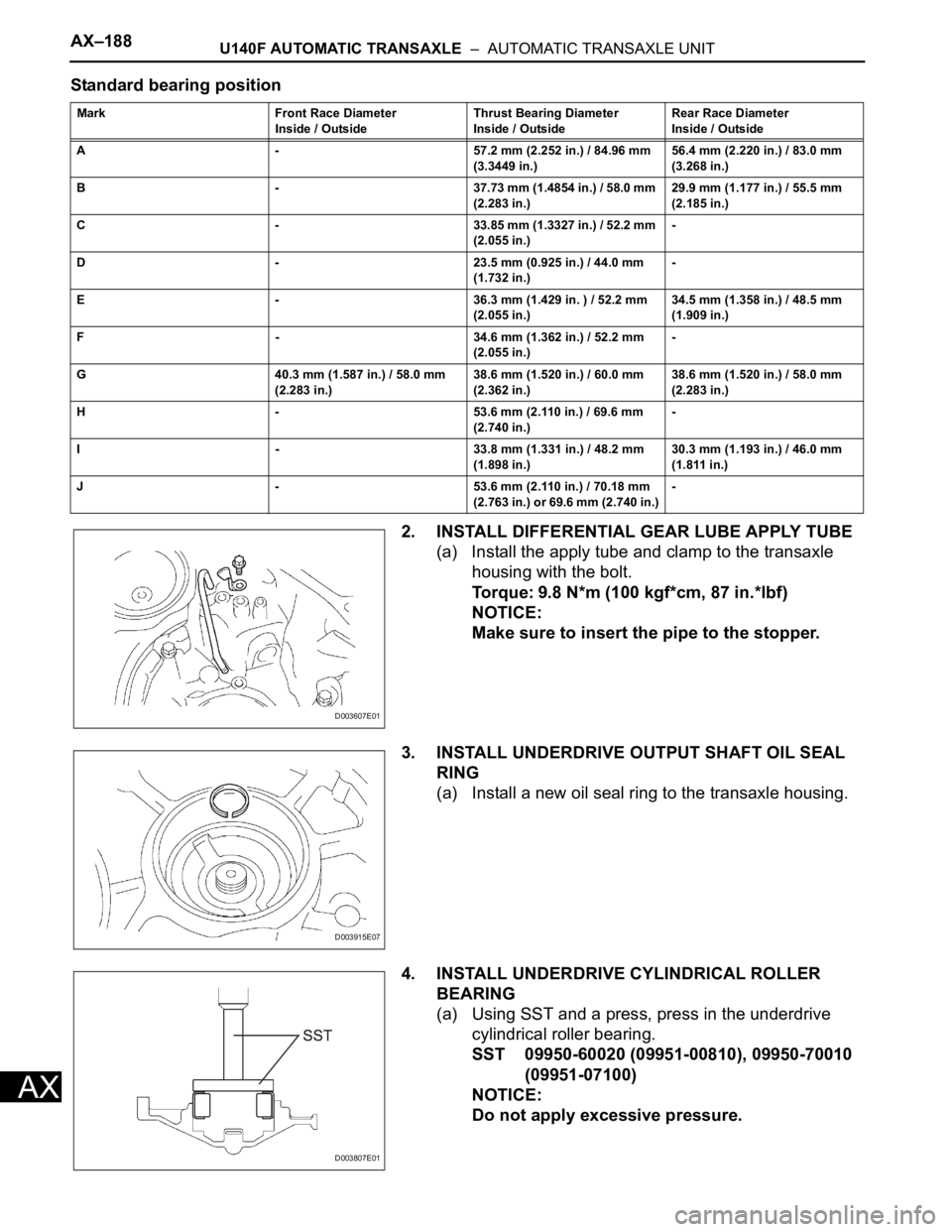
2. CHECK SPARK PLUG
(a) Check the electrode with megohmmeter:
(1) Using a megohmmeter, measure the insulation
resistance.
Standard insulation resistance:
10 M
or more
If the result is 10 M
or less, clean the plug and
measure the resistance again.
(b) Check the electrode without megohmmeter:
(1) Quickly accelerate the engine to 4,000 rpm 5
times.
(2) Remove the spark plug.
(3) Visually check the spark plug.
If the electrode is dry, the spark plug is
functioning properly. If the electrode is damp,
proceed to the next step.
(c) Check the spark plug for any damage on its thread
and insulator.
If there is damage, replace the spark plug.
Recommended spark plug
(d) Check the spark plug electrode gap.
Maximum electrode gap for used spark plug:
1.4 mm (0.055 in.)
If the gap is greater than the maximum, replace the
spark plug.
Electrode gap for new spark plug:
1.0 to 1.1 mm (0.039 to 0.043 in.)
If the electrode has traces of wet carbon, clean the
electrode with a spark plug cleaner and then dry it.
Standard air pressure:
588 kPa (6 kgf/cm
2, 85 psi)
Standard duration:
20 seconds or less
HINT:
Only use the spark plug cleaner when the electrode
is free of oil. If the electrode has traces of oil, use
gasoline to clean off the oil before using the spark
plug cleaner.
I039522E10
A088307E02
Manufacturer Spark plug type
DENSO FK20HR11
B002630E04
B062019E01
Page 954 of 2000

AX–20U140F AUTOMATIC TRANSAXLE – AUTOMATIC TRANSAXLE SYSTEM
AX
(g) Depress the accelerator pedal as much as possible
with your right foot. Quickly read the highest line
pressure reading when the engine speed reaches
stall speed.
(h) Perform the measure line pressure test again with
the shift lever on R.
Specified line pressure:
Evaluation:
Condition Shift Lever on D Shift Lever on R
Idling 372 to 412 kPa
(3.8 to 4.2 kgf/cm
2, 54 to 60 psi)672 to 742 kPa
(6.9 to 7.6 kgf/cm2, 97 to 108 psi)
Stall 931 to 1,031 kPa
(9.5 to 10.5 kgf/cm
2, 135 to 150 psi)1,768 to 1,968 kPa
(18.0 to 20.0 kgf/cm2, 256 to 285 psi)
Problem Possible Cause
Measured values at all positions are higher than specified • Shift solenoid valve SLT defective
• Regulator valve defective
Measured values at all positions are lower than specified • Shift solenoid valve SLT defective
• Regulator valve defective
• Oil pump defective
• U/D (underdrive) direct clutch defective
Pressure is low when shift lever is on D only • D position circuit fluid leak
• Forward clutch defective
Pressure is low when shift lever is on R only • R position circuit fluid leak
• Direct clutch defective
• 1st and reverse brake defective
Page 982 of 2000

AX–188U140F AUTOMATIC TRANSAXLE – AUTOMATIC TRANSAXLE UNIT
AX
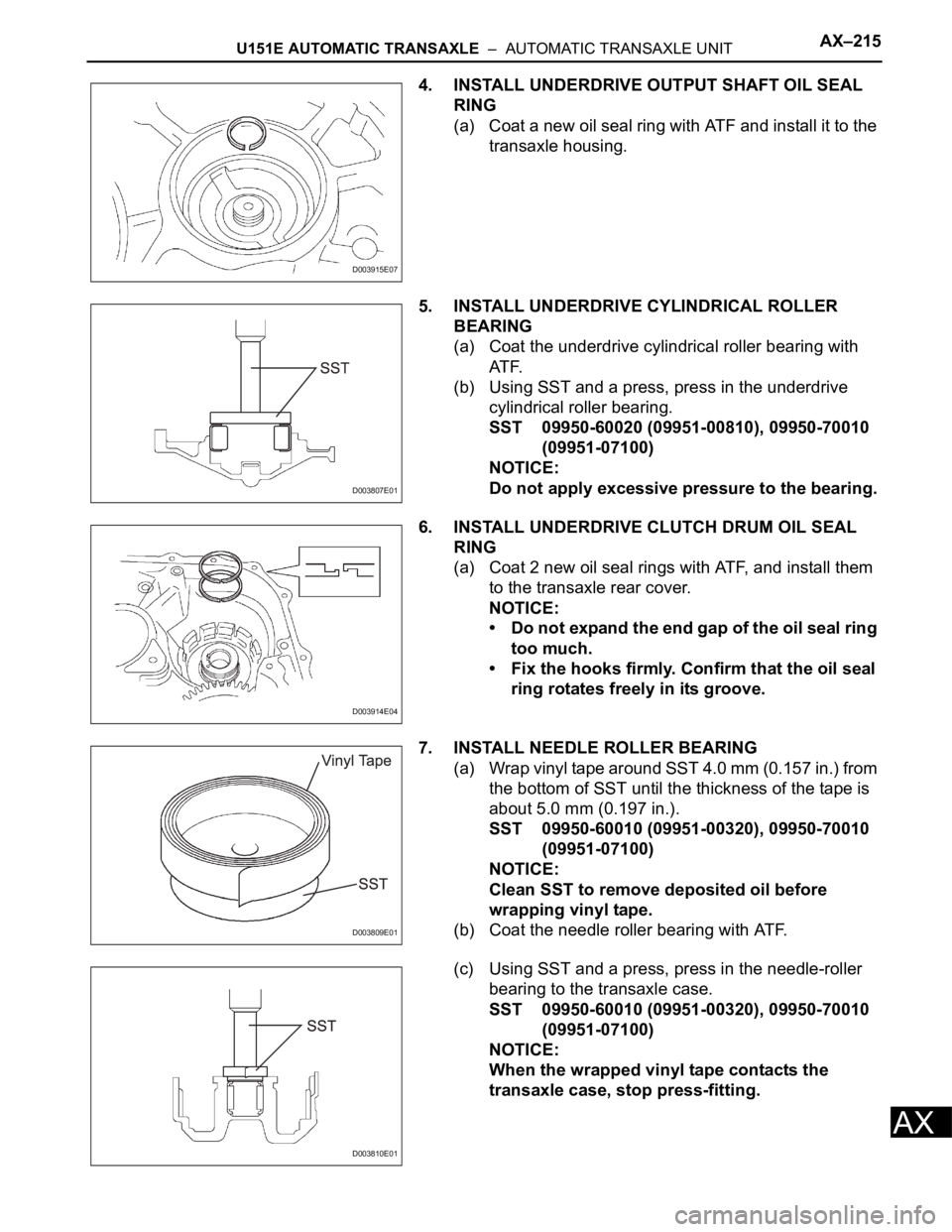
Standard bearing position
2. INSTALL DIFFERENTIAL GEAR LUBE APPLY TUBE
(a) Install the apply tube and clamp to the transaxle
housing with the bolt.
Torque: 9.8 N*m (100 kgf*cm, 87 in.*lbf)
NOTICE:
Make sure to insert the pipe to the stopper.
3. INSTALL UNDERDRIVE OUTPUT SHAFT OIL SEAL
RING
(a) Install a new oil seal ring to the transaxle housing.
4. INSTALL UNDERDRIVE CYLINDRICAL ROLLER
BEARING
(a) Using SST and a press, press in the underdrive
cylindrical roller bearing.
SST 09950-60020 (09951-00810), 09950-70010
(09951-07100)
NOTICE:
Do not apply excessive pressure.
Mark Front Race Diameter
Inside / OutsideThrust Bearing Diameter
Inside / OutsideRear Race Diameter
Inside / Outside
A - 57.2 mm (2.252 in.) / 84.96 mm
(3.3449 in.)56.4 mm (2.220 in.) / 83.0 mm
(3.268 in.)
B - 37.73 mm (1.4854 in.) / 58.0 mm
(2.283 in.)29.9 mm (1.177 in.) / 55.5 mm
(2.185 in.)
C - 33.85 mm (1.3327 in.) / 52.2 mm
(2.055 in.)-
D - 23.5 mm (0.925 in.) / 44.0 mm
(1.732 in.)-
E - 36.3 mm (1.429 in. ) / 52.2 mm
(2.055 in.)34.5 mm (1.358 in.) / 48.5 mm
(1.909 in.)
F - 34.6 mm (1.362 in.) / 52.2 mm
(2.055 in.)-
G 40.3 mm (1.587 in.) / 58.0 mm
(2.283 in.)38.6 mm (1.520 in.) / 60.0 mm
(2.362 in.)38.6 mm (1.520 in.) / 58.0 mm
(2.283 in.)
H - 53.6 mm (2.110 in.) / 69.6 mm
(2.740 in.)-
I - 33.8 mm (1.331 in.) / 48.2 mm
(1.898 in.)30.3 mm (1.193 in.) / 46.0 mm
(1.811 in.)
J - 53.6 mm (2.110 in.) / 70.18 mm
(2.763 in.) or 69.6 mm (2.740 in.)-
D003607E01
D003915E07
D003807E01
Page 1037 of 2000

U151E AUTOMATIC TRANSAXLE – AUTOMATIC TRANSAXLE SYSTEMAX–21
AX
(12)Turn the ignition switch off.
(13)Remove SST, and install the test plug A.
(14)Remove the test plug B, install SST and start
the engine.
SST 09992-00095 (09992-00231, 09992-
00271)
(15)Connect the transmission wire connector,
depress the brake pedal firmly, shift to the R
position and check the line pressure while the
engine is idling and during the stall test.
Specified line pressure:
(16)Remove SST, and install the test plug B.
(17)Clear the DTC.
Evaluation:
Condition
R position kPa (kgf/cm2, psi)
Idling 672 to 742 kPa
(6.9 to 7.6 kgf/cm
2, 97 to 108 psi)
Stall test 1,768 to 1,968 kPa
(18.0 to 20.0 kgf/cm
2, 256 to 285 psi)
Problem Possible cause
Measured values at all positions are higher than specified • Shift solenoid valve SLT defective
• Regulator valve defective
Measured values at all positions are lower than specified • Shift solenoid valve SLT defective
• Regulator valve defective
• Oil pump defective
• U/D (underdrive) direct clutch defective
Pressure is low when shift lever is on D only • D position circuit fluid leak
• Forward clutch defective
Pressure is low when shift lever is on R only • R position circuit fluid leak
• Reverse clutch defective
• 1st and reverse brake defective
Page 1089 of 2000

U151E AUTOMATIC TRANSAXLE – AUTOMATIC TRANSAXLE UNITAX–215
AX
4. INSTALL UNDERDRIVE OUTPUT SHAFT OIL SEAL
RING
(a) Coat a new oil seal ring with ATF and install it to the
transaxle housing.
5. INSTALL UNDERDRIVE CYLINDRICAL ROLLER
BEARING
(a) Coat the underdrive cylindrical roller bearing with
AT F.
(b) Using SST and a press, press in the underdrive
cylindrical roller bearing.
SST 09950-60020 (09951-00810), 09950-70010
(09951-07100)
NOTICE:
Do not apply excessive pressure to the bearing.
6. INSTALL UNDERDRIVE CLUTCH DRUM OIL SEAL
RING
(a) Coat 2 new oil seal rings with ATF, and install them
to the transaxle rear cover.
NOTICE:
• Do not expand the end gap of the oil seal ring
too much.
• Fix the hooks firmly. Confirm that the oil seal
ring rotates freely in its groove.
7. INSTALL NEEDLE ROLLER BEARING
(a) Wrap vinyl tape around SST 4.0 mm (0.157 in.) from
the bottom of SST until the thickness of the tape is
about 5.0 mm (0.197 in.).
SST 09950-60010 (09951-00320), 09950-70010
(09951-07100)
NOTICE:
Clean SST to remove deposited oil before
wrapping vinyl tape.
(b) Coat the needle roller bearing with ATF.
(c) Using SST and a press, press in the needle-roller
bearing to the transaxle case.
SST 09950-60010 (09951-00320), 09950-70010
(09951-07100)
NOTICE:
When the wrapped vinyl tape contacts the
transaxle case, stop press-fitting.
D003915E07
D003807E01
D003914E04
D003809E01
D003810E01